My most popular mode of HF operating is running mobile. This page will focus on the installation process and touch upon the equipment as needed. Antenna and installation decisions are very important in the mobile environment -- as a mobile operator you must face the fact that you're stuck with less than optimal antennas and grounding system. My current operating position is in a 1992 Ford Escort station wagon. It's a small car, with very limited options for mounting radios and antennas. In updates of this page, I will be including detailed photos of the completed installation. Above all this, the single most important task at designing a mobile station is planning. I have around 60 hours of planning and installation tied up on this project. What ever you do, don't figure on doing a first rate installation in a single day. All you'll end up with is a lousy system, busted knuckles and a bad feeling about running mobile. Start out with some goals in mind, you may come up with more:
Note: My YL doesn't drive my car, so if yours does, you'll have a #6 through #100!
Radios
Some quick tips on mobile radios. Remember that the first priority of the mobile operator is OPERATING THE CAR! Kinda hard to explain to the insurance company you were trying to dodge QRM, they'll be looking for ever for that type of car. As with most radio projects, the checkbook ends up being the deciding factor. Let's add some other factors into the equation that will help lower the cost of purchasing a mobile rig. First thing I look for is simplicity! That's right! No fancy spectrum analyzers, multi-function buttons, small knobs, switches and sliders. I've had three mobile HF rigs over the years -- an older Yaesu FT-101E, Icom 745 and my current rig is a Yaesu FT757GXII. So far the 757 seems to be the best. I can easily memorize the front panel and operate the rig without taking my eyes off the road. If you have the means to purchase a brand new rig, then go for the Icom 706MKII or the Kenwood TS-50 or TS-60. The main thing I don't like about either rig is the fact I like to monitor HF and VHF at the same time. The all in one rigs only let you monitor the current band. I also like a bright display. Unlike sitting at the home QTH, the sun can wash out most displays and render them useless while driving. So, bottom line, you can get by with a basic, no frills unit that may be a few years old. Be creative! I know the YL was glad I didn't spend mega bucks for a rig!
Antennas
Nothing gets under a hams skin as well as the subject on antennas. There are many commercial units available, and some adventuresome ops make their own. I'll just briefly touch upon antennas, as the best books available are Don Johnson's books on mobile hamming. He has a new one out and you can probably find his older ones at hamfests, etc. In general, stay away from base loaded models, and don't plan on using an antenna tuner. The monoband whips by Lakeview are excellent, and some of the best HF mobile antennas are bugcatchers or screwdrivers. Keep away from the bugcatchers that use stainless steel coils, too lossy. Lakeview makes a 40-10m bugcatcher, that I currently use. Check the antenna shootouts, etc. for performance of your particular type of antenna. Again, spend some time with Don's books -- he's been there and it saved me considerable time on deciding on an antenna.
Mounting the Radio
A good sturdy, quick release mount is very important. It must hold the rig in place, plus make it easy to remove for storing inside, or taking on trips with a different vehicle. Most amateur radio manufacturers make excellent mounts. I think the days of custom building the dash to accept the HF rig are pretty much over. The plastic in today's cars is pretty cheesy and has too many curves that make it difficult to build a face plate. The first step to determine where to mount the rig is to just sit in the driver's seat and take a look around. Go ahead, stick your arms out, all around the interior! Don't worry if the neighbors think you're strange -- just wait until the antenna is on! OK -- you think you've found a location. Just a quick note: Radios have three sides to them -- front panel, mount and connectors. So, you've solved two just now, the mount and the front panel. The next step is to get some books or whatever, and prop the rig up near it's intended location. Get on your back and crawl over the floor as far as you can under/beside the rig and take a look at the location of all of the stuff installed under and behind the dash. Boy looks crowded, eh?? Well, for starters, don't worry about the AC or heat blowing near the rig. In a modern car, that just can't always be avoided. Some things to avoid are the car's computer, blower motor(s) and running cables too close to an all electronic dashboard. Spend as much time as you need! This part is more important than mounting the antenna -- IMO. If you can't get the mount to be fastened to some good old fashioned iron behind the dash, I've beefed up the dash by using very large washers and multiple machine screws and lock washers. OK, this looks pretty good! Time to get out the Black and Decker(tm)?? NO WAIT there's more.......
Running the Cables
You'll need to look for locations to get the heavy gauge power and ground cables plus the coax out of the cab to the outside world. While you're still on your back poking your head under the dash, look at the firewall to see if there are any locations to run the power cables to the battery. You'll HAVE to run heavy gauge, 8 or larger directly to the battery. Let me say this again: you'll HAVE to run heavy gauge, 8 or larger directly to the battery. There is no way around this requirement! Place fuses on both leads, directly at the battery. The heavy cable, if it should short out can carry enough current to possibly start your car on fire! Please, buy high quality cable that is gas and solvent resistant. The run won't be long, so go ahead and splurge -- you deserve it! Have you found a location to pass through the firewall?? Yes! OK, if it's through a rubber boot -- some cars have them to pass cables in and out of the cab, go ahead and CAREFULLY slice a small slit into the boot and shove your cables through. Just be careful not to rip the boot, or haul all of the other cables along with it. To attach the cables to the battery, I needed to replace my stock battery any ways due to age. I got the biggest battery that would fit into the battery tray (measure the tray first) and a battery that had both types of terminals -- side terminals and standard top posts. Which ever pair you need to hook to start the car, you'll have another pair free! Makes it nice and tidy. While at the auto parts store, get a tube of RTV silicon sealant and a pair of terminal ends for your radio power cables. A safety note: Batteries can explode! Follow all safety directions on the battery and in your owners manual for the car. Go ahead and attach your new cable ends to one end of the radio power cables and run the other end around the engine compartment to the rubber boot you just sliced. Pay attention and keep the power cables away from ignition parts, exhaust headers or other electronic devices. It's going to be a challenge, but keep at it, you'll find a way. Use wire ties to keep it where you need. Leave the power cables about a foot longer than needed inside the cab -- allows for some shifting of the rig to install the mount, etc. Use the RTV silicon sealant to 'patch' the hole in the rubber boot where the power cables enter. This will stop engine noise, water or fumes from entering the vehicle with the engine running and you driving. What if you don't have a handy rubber boot! No problem, you'll just have an additional step: You'll have to make one! If you need to make holes through the firewall, be sure to check both sides of the firewall for attached equipment, cables, etc. It would be a real pain to drill through a brake line, or other device! Use a small drill bit first and then double check your location. Use progressively larger bits until you get to the size your grommets require. Use heavy grommets to protect the power cables, and run RTV around to seal up the holes. Did you notice that your rig has a ground lug on it?? Good, you'll need to use it. So look for a place nearby that can go directly to the car body. For my install, I had a large bolt that supported the metal frame for the dash that directly went to the firewall. Make this cable out of 1" tinned copper braid. DON'T RELY on any other cable to provide this grounding function -- power cable or coax! If you're close to a seat, the bolts that hold the seat to the floor pan make an excellent attachment point. Now is a good time to go ahead and mount the rig in it's final resting place. If you can't bolt the mount directly to some metal behind the dash, I used large 1-1/2" washers, as well as lock washers to secure it to the side of my dash. Make all of the cables the correct length to reach the rig directly, solder ALL fittings and dress properly with wire ties. A properly planned install should show only a minimum of cables, and some don't show any at all! Once all this is done, let's conduct our first noise test. First, attach a dummy load to the rig and power it up. Start the car, turn off all other rigs/radios and crank the volume on the HF rig all the way up. Listen carefully -- do you hear any buzzing or popping sounds coming out of the speaker? Rev the engine up a bit. Listen carefully -- now start at the lowest frequency of your receiver and tune through the entire HF spectrum. Are you listening carefully?? If you do hear any noise, then it's coming through the power cables, or possibly via a ground loop. Turn the rig off and disconnect the ground cable. Turn the rig back on -- here any noise?? If the noise stayed the same, then the problem is with the power cables. You may need to install some bypass caps directly at the battery. Roughly 40,000 mfd bypassed by a .01 uf cap should help. Did the noise go away?? If so, then move the ground cable to another attachment point inside the car -- you have a ground loop going. Once that is all done, take the new installation for a drive and repeat spinning the dial across the entire HF spectrum. You should be completely clean of any engine/alternator noise. Well, that wasn't so bad now was it?!? It took only about 20 hours to complete just this portion of my install.
Mounting the Antenna and COAX
Start by taking a walk around the family wagon. Get the creative juices flowing! If you're planning on running a screwdriver or the larger bugcatchers, you'll need a very STURDY mount. Go get the copy of Don's book you bought and re-read it on building antenna mounts. I have a smaller bugcatcher, so I went with a Hustler trunk mount that I modified for an additional ground strap. My antenna is guyed to the roof rack, so this mount only really has to support the weight of the antenna, not the wind load. Be sure to get the antenna as high up and away from the car body as possible. My bugcatcher coil is around 18" from the roof line, well away from the car. I modified the antenna mount to provide a heavy ground strap from the frame of the mount to the hatch. Most antenna problems can be related to poor coax, small resistance at the mount, or too close in proximity to the body. Which every mount type you choose, remember that the antenna will be outside and subject to heavy wind loading. In my first attempt at installing an antenna, the poor thing came off on the freeway, at 65 MPH while I was driving into heavy winds of 40 MPH. The antenna shot off the back, ripped the connector right off the coax and upon contact with the freeway, shattered into a million little tooth picks of fiberglass. If there had been another car behind me, and conditions were right, the metal whip could have penetrated the windshield! Use a high quality ball mount, back braced as needed. Again -- read Don's books. I use RG-213 for the majority of my run to the back of the Escort. I have a small, 'cheater' stub of RG-58A/U cable that runs through the weather-stripping on the hatch. The COAX runs from there, under the rear seats, with a small section exposed over the carpeting, to the center console. From there it runs under the console to the back of the radio. Nice and neat. Please do me a favor -- splurge again on some high quality COAX OK?? Oh, before I forget, I mount my antennas on the opposite side of the car as the tailpipe. Some ops run into tailpipe induced noise. If this is the only place you can mount your antenna, then ground the end of the tailpipe with some short braid. Should lick that problem.
RF Grounding
It's important to have a good RF ground for the mobile operator. I took heavy tinned copper braid and bonded all of the doors, hatch and hood to the body of the car. Most people don't do this, and it doesn't cost much and only takes about an hour to drill all of the holes and screw it all together. I premade all of the straps first with soldered ends, and used sheet metal screws with star and lock washers to complete the grounding kit. I used a spring loaded center punch and small drill bit to drill all of the holes. If you can, try and put these ground straps INSIDE the weather-stripping of the doors. That way it will help keep moisture and dirt from getting at the screws. It made noticeable improvements in VHF reception, plus it will help improve your portable ground plane. Some people do go as far as bonding the tail pipe, but I've never done that. Bonding the tail pipe can help eliminate RFI, more on troubleshooting RFI ( or is it caRFI?? ) in the following section.
Noise Problems
OK, some pointers on dealing with RFI from the car. I must tell you, that I've never had any noise problems in any of my installs, but YMMV or you're sitting next to a Volkswagon! The first thing to do is to determine where the noise is coming from. It can be power leads, bad ground or through the antenna. If you did a noise test before mounting the antenna, then the only place you're getting any noise is through the antenna or feed line! Pretty easy don't you think! Hopefully you won't have to move the mount. You may have to build a better ground and verify that the large piece of metal you grounded the antenna mount to is also ground with a strap to the other parts of the car. Again, get creative, crawl in the trunk, take out the back seats, find that seam in the sheet metal! Place a ground strap right there, should hopefully fix the problem. After that is you still have noise problems, then try the ARRL Handbook, etc.
Test Equipment
I don't use any real fancy test equipment when doing one of my installs. Just a good DMM, antenna analyzer and frequency counter. You don't even need the last two pieces of equipment, but it makes the job SO much easier. It took me all of 7 mins to resonate and match to 1:1 my mobile antenna initially. A standard SWR bridge and your rig can be used to tune the system, just be prepared to walk a little. I will probably be mounting a small SWR bridge inside the car, as well as permanent volt/ammeter just for the radios.
Speakers & Mics
I have three rigs in the car with me -- HF, VHF and a wide band scanner. I didn't have enough room for three external speakers! I'm currently modifying a Ramsey Kit 2.5 watt audio amplifier to handle three inputs. Will put up the schematic when I have it complete. With only one speaker, I can have a real high quality speaker that will enhance reception under noisy conditions. I also have multiple mics for the two rigs. I may combine them into just one, but will let that be until later.
Operating Tips
Well, you've managed to get the HF rig installed and get that diamond necklace to your YL for carving up the family wagon. Now you're wondering -- how do I keep track of everything like in the home shack?? Pencils, paper, logs, propagation programs, greyline, clocks! Whew.... OK, here's some quick skinny on keeping track of all this stuff. If you're into software to help you out with propagation and greyline, then just handle this stuff prior to departure. Names, QTH, rigs, time and frequency of the worked station?? I carry a small tape recorder, like the type used for dictation to use for logging purposes. Sure helps keep the old eyes on the road. If your automobile has a clock, I changed mine to UTC time. Since it's dark when I leave for work and dark when I return, I really don't need to know the local time -- if needed, I have a wrist watch! The other nifty tool for running mobile is a keypad for entering frequencies directly. The Yaesu 757 had a device called a QSYer that came along with my rig. I started using it to quickly hop around the band to switch to different nets, etc. It also switches the rig to the correct mode of operation, etc.
Maintenance
The last topic, wow, we've been through a lot so far! Routine maintenance of your installation. What's the use of going to all of this trouble to put in a first rate installation, just to have it cut down by a little crud on the connectors?? At every filling station stop, I check the antenna mount and the coax running into the interior of the vehicle. I check the matching coil on the bugcatcher and the resonance coil also. Pay close attention to the battery connections. I keep a small set of tools and a butane powered soldering iron with me to handle cleaning these things off, etc. About once a month, go over all of your ground straps. If you've managed to keep them inside the weather stripping, you shouldn't have too much problem with them. Keep your eye on the driver door one -- it gets flexed the most and replace it if it starts fraying.
ShoutOuts!
Many thanks go out to the Commute Group on the Palomar Amateur Radio Club repeater, 146.73(-) PL1B for all their comments, and essentially listening to all of my questions about rigs and antennas for the last 3 months! The commute group consists of, Jim -- KA2BLQ, Hal -- KB6RY, Rod -- AC6V, Harv -- KD6QK, Bruce -- KK6QT, Joe -- KB9MWO, and many others!
Conclusion
Hopefully this has provided you with the incentive to get into HF mobile. I will be updating this page with some photos of my current installation to help clear up any confusion. I've been asked to break it up into smaller files, and I will get to it, but not until I'm mostly done. What you're reading is work in progress! If you have any questions/comment etc, please don't hesitate to contact me!
73
Mark
email: ka6wke@amsat.org


 Profile of the beast. It's difficult to see, but there are 3 antennas mounted through the roof, right between the back door and the shell.
 Looking at the rear of the truck. The HF antenna is a KJ7U Shorty II, 160M-6M screwdriver antenna. You can read more about them at: http://www.kj7u.com.
 Oblique shot - sure looks long! It is, especially in parking lots.
 You can see the highband antennas through the roof. Left antenna is 220, middle is scanner, right is 2/440.
 This was my 4th and final attempt at installing a HI-Q 3/80 antenna. I also attempted to mount the HI-Q under the shell, first time horizontally, then vertically. I also tried mounting it in the same location as the KJ7U, but that proved to be a bad place. The HI-Q is very heavy, and long antenna so it would swing around too much. Was a real problem pulling into driveways. No matter what I did, or how I mounted the HI-Q, I just couldn't get it to work well on this truck.
 Caphat on the HI-Q. Overall length, 13' 6".
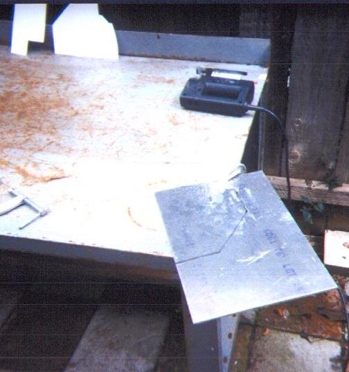
 I'm starting to install the KJ7U antenna between the shell and the top of the bed. The photo above is the final mount before sandwiching it between the shell and bed. It's bolted to the top of the bed rail, and again up through the shell. Take a look at the inside photo below for bracing to the shell.
 Finished mount, with antenna post installed.
 Mount with antenna attached. There's enough of a gap between the shell and bed to let the cables fit through without getting crunched.
 Photo of completed 500 watt amp. 4x2SC2879s. Each module puts out 250 watts.

 I first installed an Icom IC-706MKIIG, and ran with that for 3 years. I needed an HF rig for the house, and decided to upgrade the truck to the IC-7000. What a difference! Don't get me wrong, the 706 is a great rig, but the 7000 is night and day difference. The receiver is incredible in the 7000, and having IF DSP makes it a rig that's very easy on the ears. The color display is amazing as well, but difficult to read the way I have the rig installed. So, I noticed the 7000 has a video out jack, and thought installing an LCD monitor would be a great addition to the rig.


 I used a DSP speaker to help out with some of the noise, and it worked well. It's actually mounted behind the driver's seat.
 Looking under the shell, I mounted an original Don Johnson DK3 Screwdriver The red wire angled across the top of the shell.
 Since the DK3 is variable geometry antenna - meaning, it gets longer as you go down in frequency - I used a spring to keep the wire taught. I don't have a picture of the outside of the shell, so I'll have to describe it. I installed a ball mount at the top of the shell. The red wire connected to the inside of the ball mount. Outside I had a 102" whip attached to the ball. Doing all the math, that works out to a 1/4 wave on 20M going down the road. This performed very well, especially on 40 and 80M. 20M was just as good as being at home with a vertical.


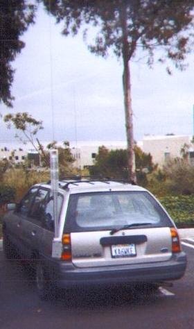
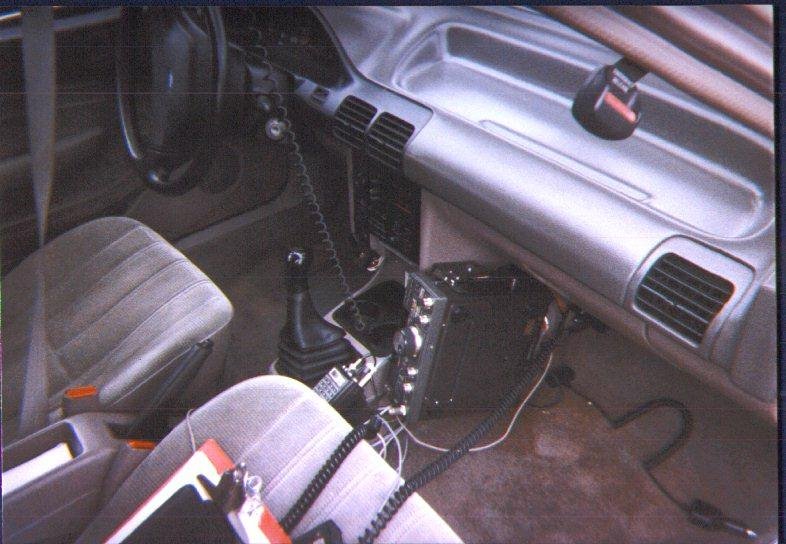 You can see the 757 mounted against the center console. Just out of sight to the right of shifter is the Icom o2-AT handheld. The 2M antenna is a magmount.
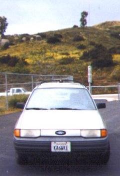 This photo shows the DK3 I was running at the time. I don't have any photos with the bugkatcher installed. I went to the screwdriver type antennas because of the difficulty it is to get back on southern California freeways during commute times. The bugkatcher was a bit quieter, and seemed to transmit a tad better than the DK3, but the remote tuning of the DK3 was more important than the performance of the bugkatcher. I worked my fair share of DX with this vehicle!
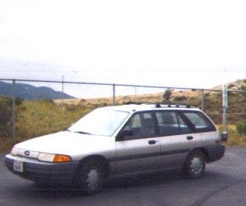