2 element 40 meter reversable quad
2 element 40 meter reversable quad

I have always endeavored to achieve that elusive free 3db of transmitted and received gain on 40 meters with a cheap wire antenna configuration. Doubling your power out without impacting your electric bill or your neighbors T.V. is obviously a nice benefit.
What I would like to describe to you is a 2 element 40 meter diamond shaped quad that is instantly reversible with usable gain and effective front to back rejection which I have affectionately named the “Just Too Easy” antenna.
There is nothing magical here that has not been done before but I was consistently disappointed with the many experiments I’ve tried using every conceivable configuration of phased lines, delay lines, and forced feeding methods ad nauseam to achieve more gain and direction switching abilities with no discernable improvement from one to the next. I figured lets stick to the physical known properties of 2 element parasitic wires. Perhaps my experiences and application might be of use to other wire antenna experimenters.
Admittedly some of my methods border on crude by most standards but my problem is I need instant gratification, {usually in the middle of a G2 storm} and if the sucker works then I will button everything up till the next big idea comes along.
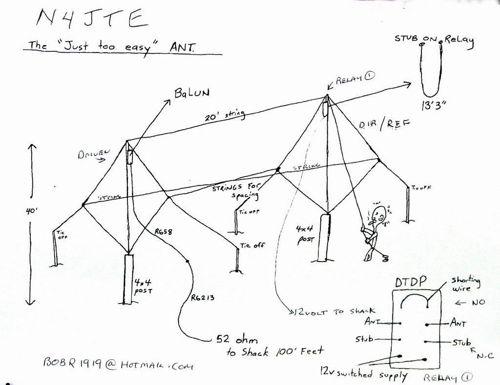
First the basic configuration; Two push up masts at 40 feet tall are spaced at 20 feet apart and attached to 8ft. 4x4 pressure treated posts sunk in the ground a couple of feet. Before raising the masts I attached an eye hook thru which the end of masonry string is run for pulling up the wires and the 52 ohm feedline and one to one balun on the driven element.
Using the standard formula of 1005 divided by frequency, {7.263}, I measured out 138 feet of #12 insulated wire from Home Depot and marked with electrical tape the 4 equal sides. The diamond shape allowed me to feed the driven element at the top, {40ft.}. I used a 40ft. length of RG 58 for it lightness and then attached RG213 for the run back to the shack. The outside corners were tied off to available supports about 24 feet high and the bottom corner {about 2 ft. off the ground} was tied down to a wood stake. The antenna is not perfectly symmetrical as I would have needed a 48 foot high mast with the bottom corner still ending up at ground level.
The second element {director/reflector} was cut to director length, 133ft. and raised to the top of second mast and tied off. The top and outside corners of each element are tied to each other with 20ft. of string to maintain spacing. The Physical antenna is now up in the air but that’s just the beginning. The Electrical antenna must now be tuned and adjusted.
I have the MFJ antenna analyzer but it stayed on the bench for this one as I prefer to check antenna resonance at the radio so the feedline and antenna properties are examined as part of the circuit. With the driven element connected to the radio in the cw mode, 5 watts is applied and a quick sweep for lowest swr is checked for and noted; that will be the resonant frequency. I needed to add about 16in. of wire to the bottom corner to achieve resonance with 139ft 4in. overall length resulting for 7.263. The swr measured 1.4 to one.
That being done it’s on to the director where I attached a temporary feedline to the bottom corner and the procedure was repeated. This time I was looking for resonance around 7.650 to achieve the 5% shortening needed for director length, first try was good, {don’t count on that} and the director was lowered for the next step.
Using the now resonant driven element length of 139ft 4in. as my constant I cut a 14ft. piece of wire,{10%} longer than driven and folded in half to form into stub. This would become the extra length of wire needed to change the director to reflector physically and electrically. A resonance test was done again with the 14ft. stub added into the antenna at the top corner and it was found to be about 9in too long to achieve my target frequency of 6.900 for reflector length. After getting it correct I disconnected the temporary feed line and wire nutted and taped the antenna ends back together. Time to get the reverse capability into the mix.
Radio Shack sells a DTDP 12 volt relay for about $6. and it was just what I needed to accomplish my goal. The direction of choice from here in upstate NY is West so I wanted the reflector stub in the circuit with the relay off. After lowering the director element, {last time, I promise} and opened up the top corner, it was time to insert the relay. The 13ft 3in. stub ends were soldered to the normally closed lugs. The antenna ends were soldered to the center lugs and a shorting wire was soldered across the normally open {director}lugs so that the application of 12 volts would short out the reflector stub and the director would now be functioning{East}. I waterproofed the relay and connections and ran some insulated double wire back to the switched 12v supply in the shack for the relay. Pulled it all back up to top while maintaining a good separation between antenna element and the 12 volt supply wire and tied off. Time for the moment of truth; or consequences.
On air results have been exceptional and made all that walking back and forth to the radio more than worth it. At .15W/L this is a really low antenna but I am truly impressed with the results. I am fortunate that I have 40 to 50 well familiar stations around the country and a few benchmark Eastern DX stations that I have communicated with nightly on the Omiss net for years. Taking into account propagation conditions etc, this real world antenna testing is an invaluable resource. Thanks guys for putting up with me.
The real fun comes with a flick of the switch from west to east with a G0 in Ireland and a CU2 in the Azores reporting a 4 to 5 S unit increase in signal strength while West reports a 5 S unit decrease, that’s a lot of DB’s. Of course at night, the downside to this, is that the foreign broadcast is pounding in; but clicking back to the West direction takes care of that in a heartbeat.
So; appreciable gain in the selected direction with resulting front to back rejection of equal or better value from 2 elements at less than ¼ w/l high from this easily constructed wire antenna makes this one definitely “ A Keeper”. Can’t wait for winter conditions.
N4JTE, Bob
Need more info ? email bobr1919@hotmail.com
I have always endeavored to achieve that elusive free 3db of transmitted and received gain on 40 meters with a cheap wire antenna configuration. Doubling your power out without impacting your electric bill or your neighbors T.V. is obviously a nice benefit.
What I would like to describe to you is a 2 element 40 meter diamond shaped quad that is instantly reversible with usable gain and effective front to back rejection which I have affectionately named the “Just Too Easy” antenna.
There is nothing magical here that has not been done before but I was consistently disappointed with the many experiments I’ve tried using every conceivable configuration of phased lines, delay lines, and forced feeding methods ad nauseam to achieve more gain and direction switching abilities with no discernable improvement from one to the next. I figured lets stick to the physical known properties of 2 element parasitic wires. Perhaps my experiences and application might be of use to other wire antenna experimenters.
Admittedly some of my methods border on crude by most standards but my problem is I need instant gratification, {usually in the middle of a G2 storm} and if the sucker works then I will button everything up till the next big idea comes along.
First the basic configuration; Two push up masts at 40 feet tall are spaced at 20 feet apart and attached to 8ft. 4x4 pressure treated posts sunk in the ground a couple of feet. Before raising the masts I attached an eye hook thru which the end of masonry string is run for pulling up the wires and the 52 ohm feedline and one to one balun on the driven element.
Using the standard formula of 1005 divided by frequency, {7.263}, I measured out 138 feet of #12 insulated wire from Home Depot and marked with electrical tape the 4 equal sides. The diamond shape allowed me to feed the driven element at the top, {40ft.}. I used a 40ft. length of RG 58 for it lightness and then attached RG213 for the run back to the shack. The outside corners were tied off to available supports about 24 feet high and the bottom corner {about 2 ft. off the ground} was tied down to a wood stake. The antenna is not perfectly symmetrical as I would have needed a 48 foot high mast with the bottom corner still ending up at ground level.
The second element {director/reflector} was cut to director length, 133ft. and raised to the top of second mast and tied off. The top and outside corners of each element are tied to each other with 20ft. of string to maintain spacing. The Physical antenna is now up in the air but that’s just the beginning. The Electrical antenna must now be tuned and adjusted.
I have the MFJ antenna analyzer but it stayed on the bench for this one as I prefer to check antenna resonance at the radio so the feedline and antenna properties are examined as part of the circuit. With the driven element connected to the radio in the cw mode, 5 watts is applied and a quick sweep for lowest swr is checked for and noted; that will be the resonant frequency. I needed to add about 16in. of wire to the bottom corner to achieve resonance with 139ft 4in. overall length resulting for 7.263. The swr measured 1.4 to one.
That being done it’s on to the director where I attached a temporary feedline to the bottom corner and the procedure was repeated. This time I was looking for resonance around 7.650 to achieve the 5% shortening needed for director length, first try was good, {don’t count on that} and the director was lowered for the next step.
Using the now resonant driven element length of 139ft 4in. as my constant I cut a 14ft. piece of wire,{10%} longer than driven and folded in half to form into stub. This would become the extra length of wire needed to change the director to reflector physically and electrically. A resonance test was done again with the 14ft. stub added into the antenna at the top corner and it was found to be about 9in too long to achieve my target frequency of 6.900 for reflector length. After getting it correct I disconnected the temporary feed line and wire nutted and taped the antenna ends back together. Time to get the reverse capability into the mix.
Radio Shack sells a DTDP 12 volt relay for about $6. and it was just what I needed to accomplish my goal. The direction of choice from here in upstate NY is West so I wanted the reflector stub in the circuit with the relay off. After lowering the director element, {last time, I promise} and opened up the top corner, it was time to insert the relay. The 13ft 3in. stub ends were soldered to the normally closed lugs. The antenna ends were soldered to the center lugs and a shorting wire was soldered across the normally open {director}lugs so that the application of 12 volts would short out the reflector stub and the director would now be functioning{East}. I waterproofed the relay and connections and ran some insulated double wire back to the switched 12v supply in the shack for the relay. Pulled it all back up to top while maintaining a good separation between antenna element and the 12 volt supply wire and tied off. Time for the moment of truth; or consequences.
On air results have been exceptional and made all that walking back and forth to the radio more than worth it. At .15W/L this is a really low antenna but I am truly impressed with the results. I am fortunate that I have 40 to 50 well familiar stations around the country and a few benchmark Eastern DX stations that I have communicated with nightly on the Omiss net for years. Taking into account propagation conditions etc, this real world antenna testing is an invaluable resource. Thanks guys for putting up with me.
The real fun comes with a flick of the switch from west to east with a G0 in Ireland and a CU2 in the Azores reporting a 4 to 5 S unit increase in signal strength while West reports a 5 S unit decrease, that’s a lot of DB’s. Of course at night, the downside to this, is that the foreign broadcast is pounding in; but clicking back to the West direction takes care of that in a heartbeat.
So; appreciable gain in the selected direction with resulting front to back rejection of equal or better value from 2 elements at less than ¼ w/l high from this easily constructed wire antenna makes this one definitely “ A Keeper”. Can’t wait for winter conditions.
N4JTE, Bob
Need more info ? email bobr1919@hotmail.com
posted by skywalker at 1:27 PM
![]()

0 Comments:
Post a Comment
<< Home