Logbook Of The World This is my preferred QSL confirmation method, especially with the costs of cards and postage nowadays. I will NOT entertain any requests for payment for you to confirm our contact via …
Model 1U71SABFRA Not amateur radio related but might serve as a reference for someone, and a future reference for me as I have 4 of these. The indoor unit started giving an error E7 flashing …
Parts of this repair could also be valid if you reversed polarity to the radio, though the survival for reverse polarity should be better as a diode (marked C further down) should just blow the …
Having been one of the initial backers on CrowdSupply, I received the LimeSDR Mini around mid-2019 and started playing with in the 2020 lock-down. Link to LimeSDR on Crowd Supply I was noticing that after …
This is my preferred QSL confirmation method, especially with the costs of cards and postage nowadays.
I will NOT entertain any requests for payment for you to confirm our contact via LOTW, if I want to donate to your expedition, I will, but I will not be held “hostage” to getting a DXCC with a PayPal payment. If this is your requirement, the contact will remain unconfirmed, I am not a DXCC or award chaser.
Not amateur radio related but might serve as a reference for someone, and a future reference for me as I have 4 of these.
The indoor unit started giving an error E7 flashing on the display and no cooling or heating – the outdoor fan was not starting at all.
I managed to find the service manual online, the PCB layout was not a 100% match but very similar, looks like some through-hole parts are SMD on my version, not to worry.
My usual disclaimer and WARNING – this time more severe than usual, usually I warn you that a mistake may damage your radio or device more, a mistake on this WILL KILL YOU ! If you are not confident with working on mains connected rectified DC (+330V at mains current), and do not have means to isolate the mains, your equipment and yourself and any other instrument you may use, DO NOT ATTEMPT this repair, engage a professional or someone who is capable of working on this. I will not be held responsible for any damage you cause to the unit, your equipment or your life, no one, including your next of kin or insurer will not hold me responsible for any damage you cause, including killing yourself by electrocution.Proceed at your own risk, or just read this article for educational purposes.
The unit uses 2 boards, a mainboard that seems to do all the control, and another board that drives the fan motor with PWM – I’m assuming this is a VFD controller – Variable Frequency Drive.
I did some quick checks before removing the boards from the outdoor unit, the service manual advises doing various checks, with most being a flow-chart, with most flows ending in “board fault – replace”, one check is if 330V DC is present on the 2 large smoothing capacitors, which there was, it was windy and cold out so I just removed the boards for inspection on the bench, hopefully, it can power up without many ancillary items. I was wrong, on the bench, rectified mains wasn’t available! looking at the layout, it seems the bridge rectifier is on the VFD board, with the mains filter caps on the mainboard, however, there was no power still, looking again it seems that an off-board PFC choke is connected to the VFD board, which remained in the unit on the roof, a quick bridge with crop-clips lead took care of that, hopefully, the PFC circuit won’t explode! – Note – Apart from using an isolated mains transformer, I current limit with a 100W light bulb in series when doing these checks, I learnt the hard way with MOSFET’s running off with fire trails on the bench!
After powering up I checked the main DC low voltages, 5V and 15V, they were not present, connected an (ISOLATED!) scope to the main switcher FET gate, and there was some pulsing, the SMPS was trying to start but was dribbling off, checked the datasheet for the NCP1200 SMPS controller, and it should have HV DC on pin 8 and a smoothing capacitor on pin 6, pin 8 was at around 290V DC and pin 6 at around 2V DC and “twitching”, hmm, let’s check the cap !
Main SMPS for AUX voltages – This is ALWAYS ON when mains is ON
This is the part where I remember that I keep telling everyone, DO NOT test electrolytic capacitors with your multimeter or capacitor meter, 99% of the time they will test good, I keep telling this to a ham friend in particular ! mehhhh — Read about ESR https://en.wikipedia.org/wiki/Equivalent_series_resistance
Cap looks good right ?? Looks even better than it should be !
Now lets test it as we should do an electrolytic ! Lets look at its ESR at 100KHz
20 ohms !! That is VERY high for a 22uF capacitorCompared to a new 22uF capacitor ! 0.018 ohms !
Replaced the capacitor and the SMPS kicked back into life, +5V and +15V now present, some relays even started to click on the board. I gave a good check to most other susceptible components, but all looked fine, there was some corrosion on the VFD board which I cleaned up and I installed the board back in the unit, I am now writing this article in a nice and warm room 🙂
Parts of this repair could also be valid if you reversed polarity to the radio, though the survival for reverse polarity should be better as a diode (marked C further down) should just blow the fuses on your DC cable.
Now to the over-voltage bit….
A linear power supply without a crowbar protection circuit is a bad idea, I supply kits on Tindie to avoid this situation. A high current linear PSU with output pass transistors (usually some 2N3055) going short circuit from Emitter to Collector could possibly feed your radio with a high current supply anywhere from 20 to 30 volts ! OUCH ! – Get a crowbar for linear PSU or go SMPS. Click HERE for Crowbar kits.
Now to this poor fellow who went through it and survived, with minor injuries, and fully repaired.
This is quite an easy fix though some care must be taken. Not all radios may fail the same, so your mileage may vary, maybe you have fewer components damaged, maybe more. The parts are cheap and easily available, I would just change them all.
The main symptom will usually be blown in-line fuses and no power. Make sure your PSU did really go high voltage. Disconnect the radio from this PSU!
Do NOT replace the internal 5 Amp fuse and connect to a power supply.
“Blowing” a fuse takes quite a bit of current (usually more than it’s rating) and quite a bit of time, the fuse is the “last-resort”, so if fuses have blown, (i shall say this in CAPS AND BOLD) THERE IS A SERIOUS SHORT CIRCUIT, DO NOT ATTEMPT TO “JUST CHANGE THE FUSE”, more damage could surely happen, semiconductors could burn out in microseconds with microamps, do you think keep putting 10’s of amps for nearly a second is going to keep them working long ? Fuses don’t blow for fun, take note !
1st, the “wash my hands” bit – DISCLAIMER
Any mistake can cause serious damage to your radio. So if you are not experienced in SMD soldering or using a soldering iron in a very FRAGILE environment – do not try to perform this fix yourself, buy the parts and a 6 pack of beer and give them to someone who can do it for you ! I will not be held responsible for any damage you cause to your radio based on this article.
On with it…..
A typical check is a multimeter on resistance/continuity/diode test mode, “beeper” will do. Check across the DC input connector on the radio, you will probably find it shorted or very low resistance, good ! hopefully the fast diodes at the DC input side have probably gone short circuit and acted before the CPU and PA transistors went bang !
Damaged ComponentsSchematic Reference
My Marking
Part Number
Usage
A
DZ2J180
18.9v Zener diode, this would probably pop first, but can’t carry enough current to blow the main fuses, it will probably go short then open circuit with high voltage at high current
B1/2/3
470μF 25v
3 pcs of 470μF 25v electrolytic capacitors, if they blew or not just change them ! This radio got 30v and they out-gassed. Yes ! LOTS OF MAGIC SMOKE !
C
DF30SC4M
40V 30A Schottky diode, this is the reverse polarity protection in fact, the surge of current still made it go short circuit in this failure
D
Fuse 5A
Mini blade flus protecting the low current side, i.e. anything not the PA, so CPU, accessories etc
E
50S06
I used a 50N05, a pretty common MOSFET, this going short blows the 5A fuse. This MOSFET “powers” on the main radio circuits, it is a “software controlled” switch as the radio by design is in sort-of “standby” let say, the PA is always “ON ” across the input power source, as is with most radios.
*F
TPSMD15A
Voltage transients suppressor, this can take quite a beating and is what probably saves the rest of the radio in this situation. I have marked it with a * simply because it is a star! well, strangely it doesn’t show up anywhere in Icom’s service manual !
All parts can be obtained from common sources, I used Mouser.
Following this repair, apply power the radio using a current limited power supply, start at 50mA to make sure there are no shorts, take it up to 500ma, then power on the radio, it should turn on and work normally, then you can move to use a high current PSU and test it on transmit, luckily the PA transistors are fine.
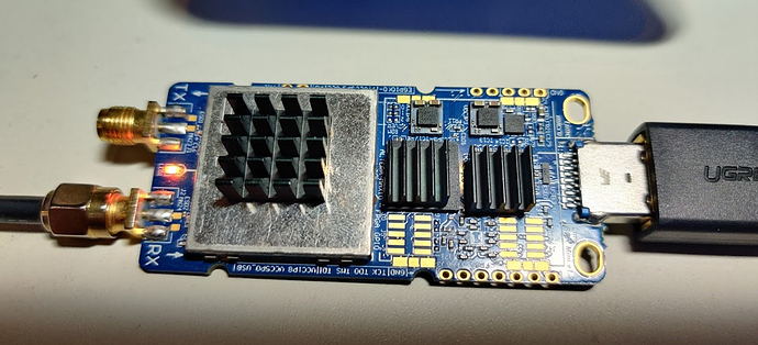
I was noticing that after using it for around 15 minutes, the received signal levels were getting lower and lower until eventually disappearing, the chips got quite warm and some forums suggested passive and/or active cooling should help with this issue. Support from Lime directly was not answered though there is a forum https://discourse.myriadrf.org with what seems to be unofficial support and user community support. I attached some mini heatsinks to the 3 chips and indeed it worked fine for many hours. The plan was to enclose the whole thing in an aluminium shielded case and put some heat transfer pads from the board to the aluminium case, with the option of adding a fan for additional cooling.
Tested with 3 mini heatsinks which made a big difference.
then it happened !
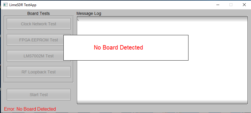
Since this was a “temporary, proof of concept”, I was trying it out to ensure it really helped, then it happened ! the mini heatsink on the USB 3 chip accidentally came loose and shorted the back of the USB 3 connector. The PC did the USB disconnect sound and the Lime disappeared from the device list 🙁
The Lime LED always powered up but the USB device could not be detected in any way. I resorted to the aforementioned forum but didn’t get many useful answers, I had to dig down to component level. Luckily the Lime is an “open” hardware project, even though they have a custom silicon, and all schematics are available on their website, though somewhat confusing sometimes with the page not always working right, but that’s another story.
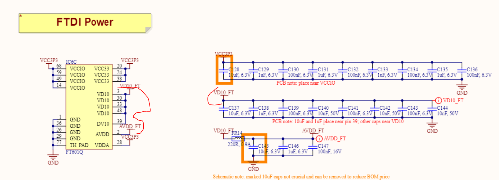
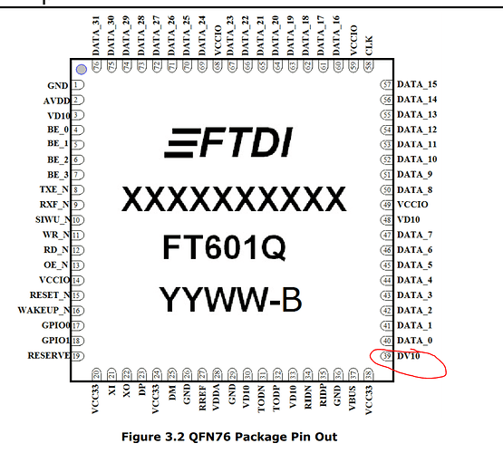
My suspicions was a dead USB 3 FIFO chip, since that’s where the short happened with the heatsink. This is an FT601Q device from FTDI
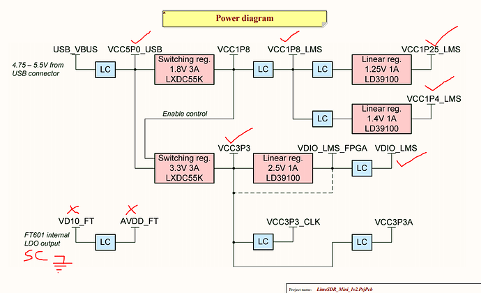
By referring and comparing to the Lime schematics and FTDI FT601Q datasheet, I was finding VCCIO and VCC33 are good but VD10 which should be +1v from an internal LDO on FT601 is not present, actually the line was short circuit to GND, to verify I checked across C147 which is on AVDD_FT line on this power bus and it shows 0 ohms to ground so was am thinking either some capacitor is SC or the FT601. I posted all this on the forum, but I didn’t get much response, maybe no hardware-level gurus on there ? Don’t know, one user did reply but responses were barely helpful, so I had to keep digging myself.
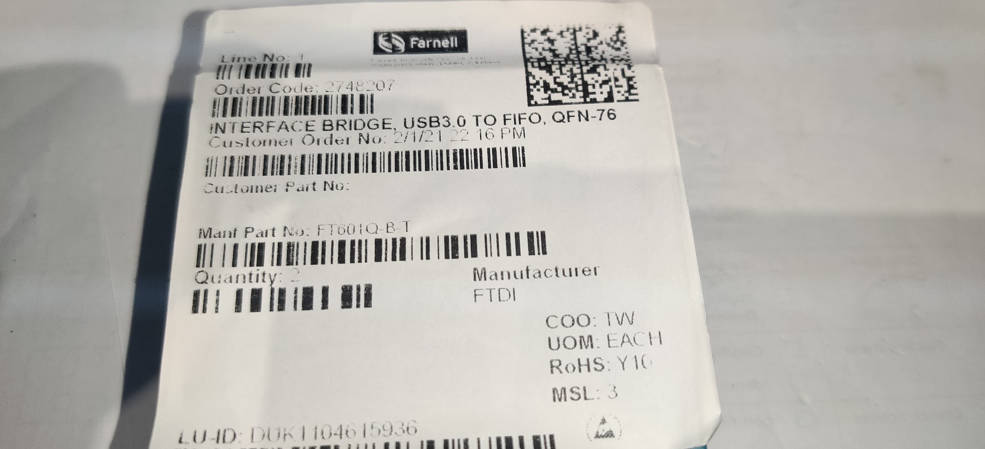
I removed the FTDI chip from the board, and alas, the short circuit on DV10, VD10 and across C147 was gone so it looks like the chip has internal SC, so I decided to replace the chip. I tried ordering this directly from FTDI, which have an online store, though they said they couldn’t sell or ship it to me ! Very strange, I tried all the usual “catalog” of suppliers but all were out of stock, though Farnell could do it on back order with a lead time of 8 months ! WOW, I bit the bullet and ordered 2. In the mean time I bought an Adalm Pluto SDR kit from Mouser, made by Analog Devices, and I totally forgot about the Lime, €200 useless module in the back of the drawer. About 6 months down the line I get an email from Farnel with a tracking number, the FT601Q was on its way and would be here in 2 days ! I ordered 2 pieces just in case.
FT601Q USB 3 FIFO chip in QFN76 package – QFN = quad-flat no-leads ! and 76 of them 🙁
I heat shielded up the board well and soldered on the chip.It went better than I thought, lots of flux helps!
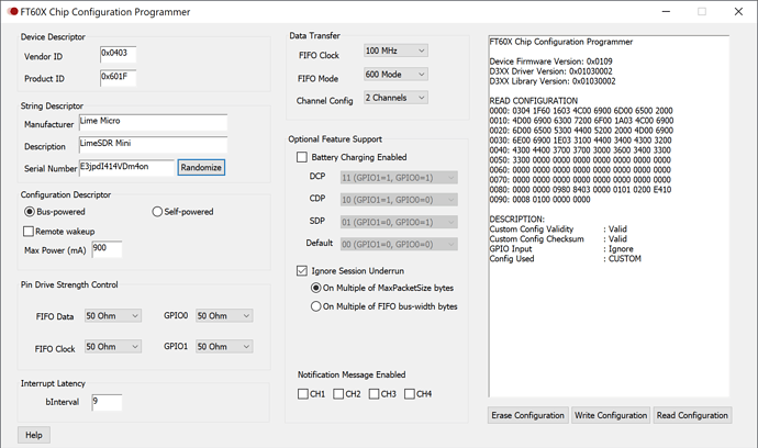
It was now or never, I made sure there were no obvious shorts, however, in the process of removing the old chip with the hot-air station, I managed to also remove C122 and C121, these are feed-through 100nF capacitors on the USB3 data lines, so it should still work in USB 2.0 mode. They are 0201 size, which is really really small, I left them out for the time being. Plugged in the USB and got the USB sound ! The FTDI chip was detected in its “unprogrammed” state
The chip can be configured using an application from FTDI. Zack on the Myriadrf forum advised the parameters used for the Lime Mini
It took some messing about to get it up and running but in the end all worked fine. I installed the 2pcs 0201 100nF capacitors and even got USB 3.0 working which is needed for larger RF bandwidth captures.
0201 are really small, could only manage them with the microscopeThe location of the 2 capacitors and the empty pad is where an ESD7016 ESD Protection Diode pack goes, which I temporarily removed for ease of access
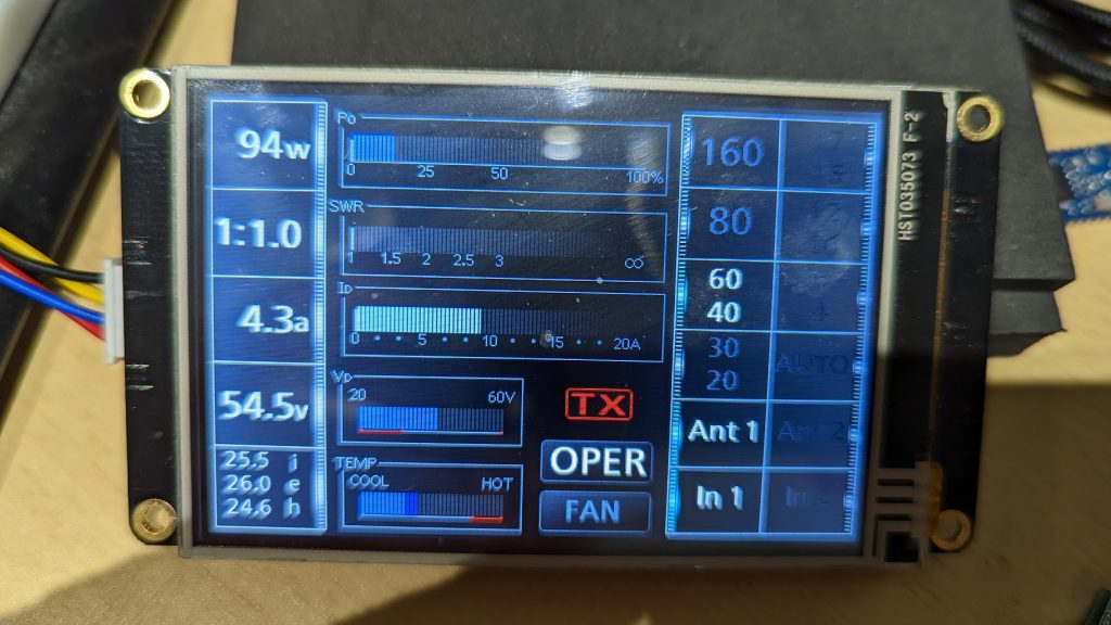
Detected and working in SDR Console and DATVExpress
Conclusions…
The Lime is now working again and I still intend to put it in an aluminium case. Though the Lime has much better specs especially on bandwidth, personally, I prefer the Adalm Pluto. I think these are nice gadgets to experiment and play with, though you cannot really compare them to shack-in-a-box SDR transceivers, especially since there is no filtering on RX and TX paths. Many people operate successfully with the Lime and Pluto on QO100, personally, I find the IC-9700 way better and much more practical.
Hopefully, this article will be of help and encouragement to someone else that comes across this issue as I didn’t find much support and assistance on the matter, by the way, I have a spare FT601Q in stock just in case anyone has difficulties like I did getting one quickly !
The Icom IC-7300 has an internal rechargeable battery to retain the running of the Real Time Clock – RTC. The battery charges when connected to your power supply, however drains deeply when left un-powered for a while. The issue seems to be that this Lithium Ion battery has a limited number of deep cycles and will eventually no longer be able to hold enough charge to keep the RTC running.
This is more of a nuisance and doesn’t really hinder the normal operations of the radio, except time-stamps on recordings or screenshots will all be labelled with the wrong date and time, typically starting at 1st January at 00:00.
Icom UK Official notice on mitigating the issue
1st, the “wash my hands” bit – DISCLAIMER
Quite a bit of heating is needed to remove the battery, and you are very close to other components, critical ones even, such as the main CPU. Any mistake can cause serious damage to your radio. So if you are not experienced in SMD soldering or using a soldering iron in a very FRAGILE environment – do not try to perform this fix yourself, buy the parts and a 6 pack of beer and give them to someone who can do it for you ! I will not be held responsible for any damage you cause to your radio based on this article.
My Solution
The best way, in my opinion, to solve this once and for all, is to replace the battery type. A non-rechargeable CR-2032, as used for the RTC on most PC motherboards should do the trick. Using a CR-2032 battery socket would make swapping the battery a 5 minute job a few years down the line.
The normal CR-2032 is NOT rechargeable, you may use a rechargeable type, but not really worth the risk of matching the charge profile and current, so an in-series diode will keep a non-rechargeable type like the CR-2032 from getting charged. The 0.6v voltage drop of the diode doesn’t bother the RTC, but may stop a few months earlier when the battery gets depleted, even though a little juice might still be there. I don’t see this as an issue, A quality branded CR-2032 is around €2 from most shops, even stationaries.
The battery is located just in the corner of the mainboard, next to the CPU
Original schematic of RTC circuit from Icom service manual
The diode shown in series with the non-rechargeable CR-2032A
A common diode such as a 1N4148 or 1N4001 may be used and is simply connected to the battery holder and covered in some heat shrink.
Affix the battery holder with some good double -sided tape to some place it cannot short anything, the top of the FPGA “screen” seems like a good place.
As you might have noticed, I have moved the website to wordpress.com. Having starting with my first website back in 1997 written in raw HTML on an Amiga 1200, this page has always been kept running over the years, either hosted on my own home server or in the last few years, on a rented VPS. I could have hosted the “free-ish” WordPress framework directly on the VPS, but in all honesty, having everything directly on WordPress itself saves me lots of hassle and time with keeping it updated, secure, patched etc so maybe I can dedicate more time to content than fiddle with raw HTML & CSS, php-extensions, packages that got deprecated over the years, but I never bothered to evolve my code etc etc. Should the need arise to integrate to any custom pages that need to really be on my own server, such as when I ran the DX cluster and QRSS grabber a couple of years ago, the option still exists. Oh well, I made it to web 2.0 I guess, took a while 🙂
Update 2022: Page moved back to my own server at Akamai, wordpress charge silly fees, I can manage a LAMP server myself, thank you 🙂
Tindie is the marketplace for makers to fund & sell their hardware creations.
I have started selling some basic kits for hobby use and also NOS parts I have too much of.
These are priced cheaply and the mark-up I make barely buys me a beer, so it is not at all a side-business, but more of a contribution to the hobby and community.
Click on the icon to go to my Tindie web store
Crowbar Protection for Ham Transceivers Kit
This has been one of my most successful kits and I hope it has been of great use and fun to build.