Search results
Query: 10 meter propagation
Links: 19 | Categories: 1
Categories
-
 This PDF article from April 2001 QST details the construction of the "NJQRP Squirt," a reduced-size 80-meter inverted-V dipole antenna. The resource provides a general construction sketch, a photograph of the assembled antenna, and specific dimensions for PC-board insulators. The antenna consists of two wire legs, each approximately **34 feet long**, separated by 90 degrees, fed at the center. It is designed for operation on 80 meters (3.5-4.0 MHz) as a quarter-wavelength antenna, requiring a low-loss feedline and an external antenna tuner due to its non-resonant feedpoint impedance. Construction utilizes readily available materials, including 1/16-inch glass-epoxy PC board for end and center insulators, and #20 or #22 insulated hookup wire for the elements. The feedline specified is 300-ohm TV flat ribbon line, with a note on potential trimming for tuner compatibility. N2CX reports the antenna's center should be elevated to at least **20 feet**, with ends no lower than seven feet above ground, resulting in a ground footprint of approximately 50 feet wide. The design prioritizes NVIS propagation for local 80-meter contacts. DXZone Focus: PDF Article | 80m Inverted-V Dipole | Construction Notes | 34 ft element length
 -
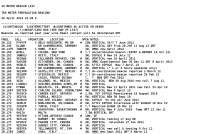 Ten meters propagations beacons compiled by Bill Hays WJ5O
 -
 The article "Exploring the World of 10 Meter Beacons" by Ken Reitz, KS4ZR, provides an in-depth look at 10-meter beacon operations, focusing on their utility for propagation analysis. It details FCC Rules part 97.203 governing beacon stations, including license requirements, power limits (under 100 watts), and the specified band segment of 28.200-28.300 MHz for U.S. operations. The content highlights the diversity in beacon construction, from converted CB radios to home-brew QRP transmitters, and discusses the robust operating conditions these 24/7 stations endure. The resource presents several case studies of active 10-meter beacon operators like Ron Anderson KA0PSE/B, Domenic Bianco KC9GNK/B, and Bill Hays WJ5O/B, detailing their equipment, antenna setups, and typical signal report volumes. It also introduces the NCDXF/IARU International Beacon Project, which features 18 synchronized beacons worldwide transmitting on 28.200 MHz at varying power levels (100W, 10W, 1W, 100mW) to facilitate propagation testing. The article also covers the PropNet Project utilizing PSK31 on 28.131 MHz and the 250 Synchronized Propagation Beacon Project on 28.250 MHz. Practical advice for monitoring includes using the RST reporting method, understanding the impact of the solar cycle on 10-meter propagation, and tips for setting up a personal beacon, such as frequency selection and power output considerations. The IY4M Guglielmo Marconi Memorial Beacon Robot on 28.195 MHz is also mentioned for its automatic QSO mode. The article concludes with a list of other resources for 10-meter beacon information.
 -
 VQLog 3.1 - 782 is a shareware logbook program designed for Windows operating systems (95, 98, NT, 2000, ME, XP, Vista, 7, 10, or later), supporting resolutions of 800x600 or higher. It can also operate on macOS and Linux via virtualization software like Virtual PC for MAC, Oracle VirtualBox, or VMware. The software facilitates QSO access by date, callsign, prefix, square, DXCC, and other parameters, offering robust import capabilities for ADIF, Cabrillo, and ASCII files from various contest and logbook programs. Key features include comprehensive award tracking for DXCC, WAZ, WAC, WPX, WAS, IOTA, TPEA, DIE, VUCC, 100EACW, and up to 30 user-defined awards. It generates customizable summaries and graphical statistics for QSO activity, DX contests, Most Wanted Squares (MWS), propagation openings, and prefixes. VQLog supports DX-Spot reception and processing from DX-Cluster and PSK-Reporter with programmable warnings, integrates with callbook services like QRZ.COM and Buckmaster's CD, and offers online lookup. Electronic QSL and log upload support extends to LoTW, eQSL.cc, Clublog, and DXMAPS, with real-time updates for online logs. The program provides extended QSO information for VHF-DXers, including separate TX/RX frequencies, start/end times, propagation modes, and specific entry fields for MS, EME, and Tropo. CAT support for rig control and interfaces with ARSWIN and PstRotator for azimuth/elevation control are also included.
 -
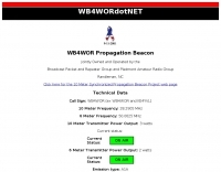 WB4WOR Propagation Beacon on 6 and 10 meters Jointly Owned and Operated by the Broadcast Packet and Repeater Group and Piedmont Amateur Radio GroupRandleman, NC USA
 -
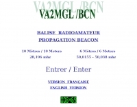 Info and specifications on my three beacons on 10 and 6 meter bands. You will find also informations on the propagation for these two band.
 -
 Demonstrates the operational status and reception reports for the SK6RUD/SA6RR QRPP beacons, which transmit on 478.9 kHz, 1995 kHz, 10.131 MHz, and 40.673 MHz. These beacons utilize extremely low power, with the 630-meter beacon operating at approximately 0.1 watt ERP into an L-antenna, showcasing the potential for long-distance contacts under favorable propagation conditions. The site details the specific frequencies and antenna types employed, such as a vertical at 500 kHz and a 1/4 vertical for higher bands. The resource compiles over 10,530 reception reports from amateur radio operators worldwide, logging details such as date, time, band, RST signal report, locator, distance, and receiver setup. Notable long-distance reports include a 500 kHz reception by AA1A-Dave from 5832 km in 2008 and a 10.133 MHz reception by ZL2FT-Jason from 17680 km in 2010, illustrating the global reach of these low-power transmissions. Each log entry provides specific equipment used by the reporting station, including transceivers like the Yaesu FT817, ICOM IC-7300, and various antenna configurations such as coaxial mag loops, inverted Ls, and end-fed wires. The primary objective of the SK6RUD beacons is to challenge conventional notions of power requirements for effective two-way communication, proving that contacts over significant distances are achievable with minimal output. The site also includes a submission form for new reception reports, fostering community engagement and continuous data collection on propagation phenomena across different bands. The detailed logs offer practical insights into real-world propagation characteristics and the efficacy of QRPP operations.
 -
 KB9AMG's Top WSPR Spots presents a focused online tool for monitoring **2-way WSPR reports**, specifically detailing propagation data from February 2026 through March 2026. This resource aggregates _WSPRnet_ data, allowing radio amateurs to observe weak signal propagation conditions across various bands. The interface is straightforward, presenting callsigns, frequencies, signal-to-noise ratios, and distances for each reported contact, which is crucial for understanding current band openings and signal paths. The utility of this WSPR spotter lies in its ability to quickly visualize global propagation. Users can identify active stations and assess signal viability over long distances, with reports often showing contacts spanning thousands of kilometers. For instance, a typical WSPR report might indicate a signal from Europe reaching North America with a _SNR_ of -25 dB, demonstrating effective low-power communication. This data is invaluable for planning DX operations or evaluating antenna performance under actual propagation conditions.
 -
 On March 27, 2017, the FCC adopted final rules for the USA 630-meter band, detailed in Report and Order FCC 17-33, which required PLC coordination with the Utilities Telecom Council before amateur operations could commence. This resource documents the WD2XSH experimental group's activities, including authorized stations, band plans, and frequency assignments within the 465-515 KHz range, with many stations operating between 495-499 KHz and 501-510 KHz. The site also highlights the WRC-12 decision on February 14, 2012, which granted a new **7-kilohertz-wide** secondary allocation between _472-479 kHz_ for the Amateur Radio Service worldwide. The group's efforts included operating with a maximum ERP of **20 Watts** across 45 stations in the continental USA, Alaska, and Hawaii, using emission modes such as CW, PSK-31, FSK-31, and MSK-31. The site provides links to download FCC 17-33 in PDF and DOCx formats, and offers a station location map, a list of stations by callsign and frequency, and an archive of news updates. Reception reports for any 600-meter station are encouraged to help the amateur radio community understand propagation and repeatability on this challenging band.
 -
 Fifty-three digital modes, including PSK31, RTTY, and JT65, are explored in this resource, providing detailed descriptions of their underlying technologies and typical use cases. It covers error correction methods like ARQ in PACTOR and FEC in JT65, alongside modulation schemes such as FSK and PSK. The content highlights the evolution of digital communication from traditional TNC-based systems to modern sound card implementations, emphasizing the role of personal computers in advancing these modes. Specific modes like AMTOR, PACTOR, and G-TOR are discussed, noting their baud rates and error correction capabilities. For instance, AMTOR operates at 100 baud, while PACTOR offers 200 baud with Huffman compression. The article also delves into newer modes like MFSK16, which uses 16 tones and continuous Forward Error Correction, and Olivia, capable of decoding signals 10-14 dB below the noise floor. Each mode's bandwidth, speed, and resilience to propagation challenges are examined, such as MT63's 1 KHz bandwidth and 100 WPM rate, or Hellschreiber's 75 Hz bandwidth and 35 WPM text rate. The resource also lists predominant USA HF digital frequencies for bands like 160, 80, and 40 meters, specifying segments for PSK31, RTTY, SSTV, and Packet. It includes links to freeware and shareware sound card software such as Digipan, FLDigi, and MixW, enabling amateurs to experiment with these modes.
 -
 The Boone Area Radio Klub (BARK) serves Boone County, Iowa, as its local amateur radio club, actively welcoming visitors to its meetings and weekly ARES nets. The club maintains a 2-meter repeater on 146.850/250 MHz with a 114.8 Hz tone and a 440 MHz repeater on 443.9+ MHz, both situated at the Boone County Hospital, with a simplex fallback on 146.550 MHz for the 2-meter net. Additionally, BARK supports the Iowa 160-meter ARES net at 1.972.5 MHz, which operates at 9:30 PM on Sundays, featuring a rotating schedule of net controls including KNØR, KBØMPL, NØISU, KEØQEU, and KBØLPI. BARK conducts bimonthly license testing sessions on the second Saturday of even-numbered months, with specific dates like October 19, 2024, at the Hamboree, requiring a $15 fee and prior FCC Registration Number (FRN) acquisition. The club's activities are well-documented through numerous photo galleries from past Field Days (1998, 1999, 2008, 2010, 2013, 2017, 2018, 2019), JOTA events (2013), and special event stations (2010 B&SVRR&M). Members like KBØMPL (Margot Conard) have contributed educational PowerPoint presentations on topics such as "Fun with Handie Talkies," "HF Propagation," and "Digital Mode - FLDIGI - OLIVIA 8/500 - JT65 HF - BAND PLANS." The club's officers, as of May 2018, include WØFS (Clay Conard) as President, NØISU (Mitch Carroll) as Vice-President, and KBØLPI (Eric Sloan) as Treasurer/Secretary, guiding the club's operations and community engagement.
 -
 Low-frequency (LF) radio time signals, operating primarily in the 40–80 kHz range, are broadcast by national physics laboratories for precise clock synchronization. Transmitters like **JJY** (40 kHz, 50 kW; 60 kHz, 50 kW), RTZ (50 kHz, 10 kW ERP), MSF (60 kHz, 15 kW ERP), WWVB (60 kHz, 50 kW ERP), RBU (66.66 kHz, 10 kW), and DCF77 (77.5 kHz, 50 kW) cover vast geographic areas, often several hundred to thousands of kilometers. LF signals offer distinct propagation advantages over higher-band transmissions such as GPS. Their long wavelengths (3–6 km) enable effective diffraction around obstacles like mountains and buildings. The ionosphere and ground act as a waveguide, eliminating the need for line-of-sight and allowing a single powerful station to cover extensive regions. Ground wave propagation minimizes ionospheric variability effects on transmission delay, and signals penetrate most building walls effectively. Robust and low-cost receivers, often priced at 20–30 USD/EUR, are widely used in radio clocks. These receivers typically comprise a tuned ferrite core antenna, a receiver IC (e.g., Atmel T4227, U4223B, MAS1016) for amplification and AM detection, and a microcontroller for decoding the time signal and phase-locking a local clock. Specific components for DCF77, MSF, and WWVB are readily available from vendors like HKW Elektronik and Ultralink.
 -
-
 N4PAL 10 Meter, 28.214MHz Radio Beacon Site Information and Siginal Report Logging
 -
 Microwaves101 provides an extensive repository of information covering fundamental principles of microwave design, targeting engineers and radio amateurs interested in the higher frequency spectrum. The site features a detailed _encyclopedia_ of microwave terms and concepts, alongside practical design considerations for various components and systems. It serves as a foundational reference for understanding RF propagation, transmission lines, and active/passive microwave circuits. The resource includes numerous calculators for impedance matching, filter design, and other critical RF parameters, facilitating hands-on project development. Discussions on **10 GHz** equipment and **24 GHz** projects highlight practical amateur radio applications, extending to operations up to 134 GHz. Content spans from basic theory to advanced topics like MMIC design and antenna characteristics, supporting both educational and practical endeavors in microwave technology.
 -
 This blog chronicles the development of an 80-meter vertical antenna for amateur radio operation. The author constructs a top-loaded vertical using fiberglass poles, achieving significant performance improvements over their previous end-fed wire antenna. Comparative testing using the Reverse Beacon Network and on-air contacts demonstrates 8-10 dB gain on the east coast. The project evolved to include 40-meter capability through a modified design featuring a four-wire vertical cage, loading coil, and strategic guying system. Despite challenges with signal wobble during windy conditions, the vertical consistently outperforms the end-fed wire, particularly for reaching distant stations during nighttime propagation.
 -
 Come learn why it is very difficult to predict propagation on the top band. Ionospheric Variability, Time Variations of Ionospheric Parameters, Atmospheric Gravity Waves, Ionospheric Absorption and The Role of Negative Ions.
 -
 This article examines how geomagnetic activity influences 160-meter radio propagation. K9LA analyzes observations of enhanced signals preceding K-index increases. Modeling shows that as ionospheric electric fields rise from 0 to 75 mV/meter during early geomagnetic storms, they create an electron density valley above the E region, enabling signal "ducting" between the E and F regions. This effect vanishes at higher field strengths (100 mV/meter). The phenomenon may explain both exceptional 160m openings preceding 6m propagation and possibly Marconi's contested 1901 transatlantic reception, which occurred during a small geomagnetic disturbance.
 -
 The Olivia digital mode, a **Multi-Frequency Shift Keying (MFSK)** radioteletype protocol, is specifically engineered for robust communication under difficult propagation conditions on shortwave radio bands from 3 MHz to 30 MHz. Developed by Pawel Jalocha in 2003, Olivia signals can be decoded even when the noise amplitude exceeds the digital signal by over ten times, making it highly effective for transmitting ASCII characters across noisy channels with significant fading and propagation phasing. Early on-the-air tests by Fred OH/DK4ZC and Les VK2DSG on the Europe-Australia 20-meter path demonstrated intercontinental contacts with as little as one-watt RF power under favorable conditions. Common Olivia modes are designated as X/Y, where X represents the number of tones and Y is the bandwidth in Hertz, with examples including 8/250, 16/500, and 32/1000. The resource clarifies that Olivia, unlike some other digital modes, produces a constant envelope, allowing RF power amplifiers to achieve greater conversion efficiencies and making it less prone to non-linearity. Operators are advised that **Automatic Level Control (ALC)** can be set higher than no meter movement for MFSK modulation, as long as it's not driven past its high limit, contrary to common misinformation about other digital modes. The Olivia community encourages voluntary channelization on suggested calling frequencies, such as 14.0725 MHz for 8/250, to facilitate initial contacts, especially for signals below the noise floor. The Olivia Digital DXers Club provides links to Groups.io, Facebook, and Discord for community engagement and offers details on QSO parties.