Search results
Query: 144 meter
Links: 61 | Categories: 1
Categories
-
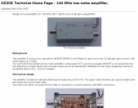 Design of a preamplifier for 144 MHz with 1 dB NF and 23 dB gain using BF981. This amplifier is using a low cost silicon MOSFET (BF981 from Philips) to give more than 20 dB gain with around 1 dB noise figure on 2 meter.
 -
-
 Operating on the HF bands, Kenwood's TS-990S and TS-890S transceivers represent their flagship offerings, providing advanced features for DXing and contesting. My personal experience with Kenwood gear, particularly the TS-590SG, confirms their reputation for solid receive performance and clean transmit audio, often noted in pileups. The TS-590SG, a popular choice for many hams, delivers reliable performance across the HF and 6-meter bands, making it a versatile station centerpiece. For VHF/UHF enthusiasts, the TH-D75A tribander offers 144, 220, and 430 MHz capabilities in a portable form factor. This handheld unit integrates D-STAR and APRS functionalities, appealing to operators who value digital modes and location-based services on the go. The inclusion of 220 MHz, a less common but valuable band, expands its utility for regional communications and specialized nets. Kenwood's enduring presence in the amateur radio market, dating back to 1955, underscores a commitment to quality and innovation. Their product range, from high-end base stations to feature-rich portables, continues to support a wide array of operating styles and technical requirements within the ham community.
 -
-
-
-
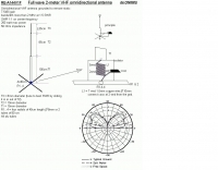 A full wave 2-meter VHF omnidirectional antenna by ON6MU
 -
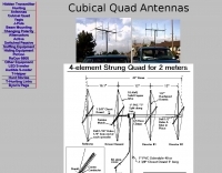 A project by N6BG for a four element cubical quad antenna for the 2 meters band
 -
 Mobile vertical antenna for 144 MHz suitable for satellite signals reception by K5OE
 -
 A homebrew project for a 2 meter 4 element yagi beam antenna by 2E0HTS
 -
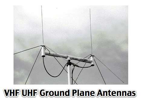 Phased array Ground Planes antennas for 144 Mhz
 -
 A VHF Quad antenna for teh two meters band in italian
 -
-
-
 A vertical linear loaded antenna for 2 meters band in italian
 -
 W5GVE article on homebrewing a 144 MHz DDRR antenna for mobile use
 -
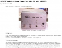
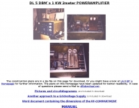 Pictures and circuit diagramm to build this power amplifier for 2 meters
 -

-
 A 144 MHz dipole antenna made from coax, PVC pipe, and aluminum foil tape
 -
 VU2RAR basic VHF power amplifier suitable for 144-146 Mhz output power can vary from 3 to 25 Watts.
 -
 The RigPix database entry provides a comprehensive technical overview of the Icom IC-746 amateur HF/VHF transceiver, detailing its operational parameters and physical characteristics. It specifies the transmit frequency ranges across 10-160 meters plus WARC bands, 50-54 MHz, and 144-146/148 MHz, alongside receive coverage from 0.03-60 MHz and 108-174 MHz. The resource outlines supported modes including AM, FM, SSB, CW, and RTTY, noting a tuning step resolution down to 1 Hz and a frequency stability of ±5 ppm. Key electrical specifications are presented, such as a 13.8 VDC power supply requirement, current drain figures for RX (1.8-2 A) and TX (Max 20 A), and RF output power ranging from 5-40 W for AM and 5-100 W for FM, SSB (PEP), and CW. The entry details the triple conversion superheterodyne receiver system, listing IF frequencies at 69.01 MHz, 9.01 MHz, and 455 KHz, along with sensitivity ratings for various modes and bands. Transmitter section specifics include modulation systems and spurious emission levels. Additional features like a built-in auto ATU, electronic keyer, simple spectrum scope, DSP, and CI-V computer control are noted. The page also lists related documents, modifications, and an extensive array of optional accessories, including various filters, microphones, and external tuners, providing a complete profile of the IC-746.
 -
 F5RDH project of a transverter, that can receive input in HF and convert output to 144 Mhz in french
 -
 By ON4CFC Pascal, describe how to build a Sperrtopf or Sleeve antenna for the 144 Mhz, PDF File by antennex
 -
 The Grid Yagi (or Grid Quad) is a high performance yagi antenna that can be built with readily obtainable inexpensive materials. Described here is a 6 element 2 meter version with a boom length of about 1 wavelength, shown
 -

-
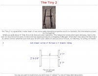 The "Tiny 2" is a great little 2 meter beam. It has some really interesting properties and it is a fantastic first time antenna project for the beginner.
 -
 An homebrew crossed Yagi antenna for two meters band based on DK72B design with pictures, detailed description and tricks by Barry Zarucki M0DGQ
 -
 A home made vertical polarized moxon antenna for 144 MHz, includes dimensions, antenna pattern, SWR and antenna gain plots by WB5CXC
 -
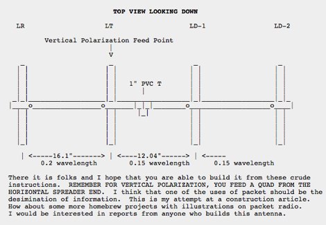
 A portable 4 elements quad antenna for 144 MHz, 9 to 10 DBd forward gain, 30 DB front-to-back ratio, and 33 DB front-to-side ratio
 -
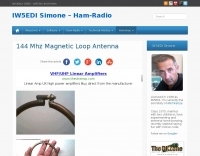
 A copper pipe Hentenna for 144 MHz. The Hentenna, a compact, high-gain loop antenna developed in Japan in the 1970s, offers approximately 5.1 dBd gain, comparable to a three-element Yagi. Adapted for 2 meters, it is crafted from copper pipe for simplicity, affordability, and broadband performance. Requiring no feed-point tuning, its construction involves soldering standard copper fittings. Installation demands non-conductive materials to minimize signal disruption. Versatile for vertical or horizontal polarization, it is ideal for FM, repeater, SSB, or CW applications. This design emphasizes practicality and performance for amateur radio enthusiasts
 -
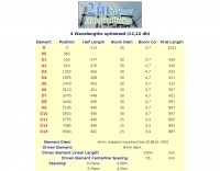
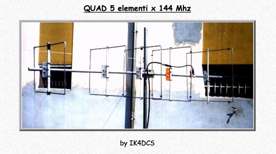
 A five element quad antenna for 144 MHz DIY Project. This 2 Meter 5 Element Quad antenna was modeled using EZNEC, with a boom from a UHF TV antenna and CPVC pipe for spreaders. Constructed for 146MHz, it exhibits a gain of 10.7dB and an impedance of 75 ohms. Real-world results surpass the HT antenna, reaching over 20 repeaters up to 75 miles away. The design, costing around $10, employs simple tools for assembly.
 -
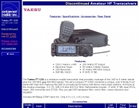 The Yaesu FT-100 is a miniature mobile transceiver that provides coverage of the 160 to 6 meter bands plus the 144 MHz and 430 MHz bands
 -
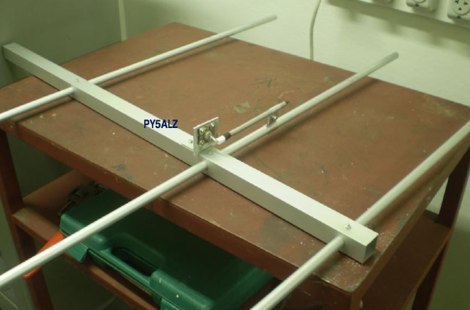 A 3 element yagi antenna project for the 144 MHz band by PY5ALZ in portuguese
 -
 A project for a home made 5 element yagi-uda antenna for 2 meters, covering 144-148 MHz band by N1BMX
 -
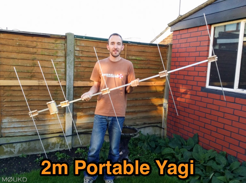 Building a 2 metre 144MHz VHF Yagi beam antenna, designed for portable use.
 -
-
 Demonstrates the construction of a 144 MHz turnstile antenna, detailing its design for omnidirectional, horizontally polarized VHF operation. The resource outlines the physical dimensions and materials required, including specific lengths for the radiating elements and the use of _RG-58_ coaxial cable for phasing. It covers the assembly process, emphasizing the critical spacing and connection points to achieve the desired radiation pattern and impedance matching for the _2-meter band_. The article presents measured _SWR_ performance across the 144-146 MHz segment, showing a low SWR of 1.2:1 at 144.5 MHz, which is suitable for general VHF use. It compares the turnstile's performance to a 9-element Yagi, noting the turnstile's advantage in providing consistent signal strength from all directions without requiring a rotator. Practical application for local FM simplex and repeater operations is implied, offering a simple yet effective antenna solution for fixed or portable stations.
 -

-
 The Yaesu VX-5R, manufactured between 199x and 200x, offers a transmit frequency range covering 50-52 MHz, 144-146 MHz, and 430-440 MHz for European models, with US versions extending to 50-54 MHz, 144-148 MHz, and 430-450 MHz. Its receiver boasts an impressive wideband capability from 0.5 MHz to 999 MHz, with cellular frequencies blocked in some regions. The unit provides up to 5 watts RF output on 6 meters and 2 meters, and 4.5 watts on 70 centimeters, with selectable lower power settings down to 300 mW. This handheld transceiver utilizes a double conversion superheterodyne receiver system, featuring a 47.25 MHz first IF for FM and 45.8 MHz for WFM. Key specifications include a frequency stability of ±5 ppm across a wide temperature range and a current drain of 25-150 mA on receive. The VX-5R supports 220 regular memory channels with alpha tags, 3 home channels, and 10 NOAA weather channels, all stored in non-volatile EEPROM. Additional features include CTCSS/PL and DCS with tone search, ARS, ARTS, an internal voltmeter, and a Spectra-Scope. The device operates on a 7.2 VDC battery pack or 10-16 VDC external power, weighing 255 grams with dimensions of 58x88x27 mm. The VX-5R was also available as the metallic silver VX-5RS.
 -
 A 144 Mhz Slim Jim Antenna, aluminum tubing version project by Mohammad 9W2WTF
 -
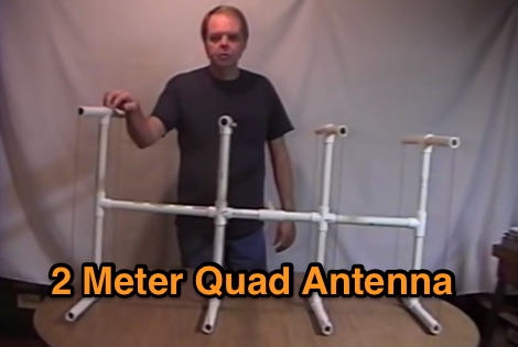 A four elements quad antenna for 144 MHz made with PVC pipes
 -
 A 4 elements Yagi-Uda antenna for 144.3 MHz plan with dimensions and yagimax dimension calculation
 -
 DK0WCY transmits 24 hours per day on 10144 kHz in the 30 meter amateur radio band. QTH in Scheggerott JO44VQ
 -
 During a club's "Filetto Day" event, a comparative field test was conducted between a **Buddipole** antenna and a homemade 20/40-meter wire dipole. The author, IW5EDI, performed this personal evaluation from a mountain top at 1500 meters above sea level, utilizing a Yaesu FT-857D transceiver to switch between antennas. The observations on the 20-meter band indicated that the wire dipole consistently delivered significantly stronger signals compared to the Buddipole. Additionally, the Buddipole exhibited higher levels of **QRM** during the listening tests. The commercial Buddipole, known for its multiband capability and compact size with a self-supporting tripod, was contrasted with the simpler, larger wire dipole, which required a fiberglass fish pole for support. This direct comparison highlights practical differences in performance and deployment between a popular portable commercial antenna and a basic wire antenna in a real-world operating environment.
 -
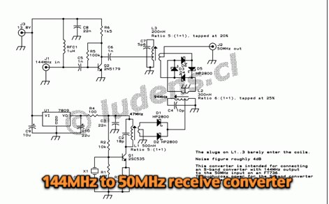 A simple accessory for a satellite station, that allows using a 6 meter capable radio in conjunction with a typical S-band to 2 meter converter
 -
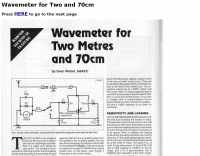 G8ACC article project for a 144 & 430 MHz wavemeter
 -
 A great and efficient monoband VHF portable antenna. The article consist of two version of a 12.5 Ohm 3 elements yagi beam antenna plans for the two meter band, a full sized and a shortened version expecially designed for the SSB and CW on 144 MHz.
 -
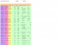
 Presents a historical timeline of amateur radio satellites, beginning with the inaugural _OSCAR 1_ in 1961 and extending through ARISSat-1 in 2011. It outlines the evolution of these orbiting transponders, initially simple battery-operated beacons, into sophisticated platforms supporting educational initiatives, emergency communications, and technology demonstrations. The document highlights the significant contributions of various AMSAT organizations and other entities in developing and deploying these spacecraft. Each entry provides specific launch details, including the date, launch vehicle, and initial orbital parameters such as apogee, perigee, and inclination. For instance, AMSAT-OSCAR 7 (AO-7) launched in 1974 into a 1459.00 x 1440.00 Km orbit, while AMSAT-OSCAR 40 (AO-40) achieved a highly elliptical 58665.00 x 1157.00 Km orbit. The resource also notes the allocated amateur satellite service frequencies, including 29 MHz (10m), 145 MHz (2m), 435 MHz (70cm), 1270 MHz (24cm), and 2400 MHz (13cm). The compilation serves as a concise reference for understanding the progression of amateur satellite technology and operations over five decades, showcasing the collaborative efforts of the global amateur radio community in space communication endeavors. It details the physical characteristics and project affiliations for many of the **20** satellites listed, providing a foundational historical context.
 -
 HamGear.eu page about the FT-100, 160 to 6 meter bands plus the 144 MHz and 430 MHz bands transceiver from Yaesu.
 -
 Developing operational amateur radio equipment for the 134 GHz band presents significant technical challenges, particularly in frequency generation and stability. This resource details the construction of a 134 GHz system, outlining its architecture with separate transmit (Tx) and receive (Rx) modules, each employing a local oscillator (LO) and RF head units. The system utilizes a dual Flann 50 GHz lens-type horn antenna configuration for optimal signal coupling. The transmit path incorporates an LMX2541 synthesizer chip operating at approximately 2.8 GHz, referenced by a 10 MHz double-oven Morion OCXO for exceptional stability. This signal is multiplied through a series of stages (X4, then X2) to generate a 22.4 GHz signal, which subsequently drives a dual series diode multiplier to produce the final X6 signal for 134 GHz operation. The receive side features an anti-parallel diode mixer coupled to a 144 MHz transceiver via a preamplifier, ensuring effective downconversion. Operational mode is CW, achieved by keying a multiplier stage. The project includes images of the Tx and Rx head units and describes a successful 3.5 km test with G8ACE, demonstrating stable signal tones due to PLLs locked to OCXOs at both ends, confirming the system's robust performance.