Search results
Query: 23 com yagi
Links: 15 | Categories: 0
-
 Build your own antenna for the 23cm band ( 1250Mhz - 1280Mc ) using some aluminium and this simple design.
 -
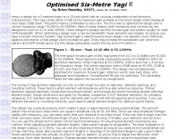 Design for a 5 element beam on a 23 foot boom with an unusual combination of performance characteristics
 -
-
 This document details the design and construction of a Vinecom 6N4 dual-band Yagi antenna for the 50MHz (6-meter) and 70MHz (4-meter) amateur radio bands. The antenna features 9 total elements (4 elements for 50MHz, 5 elements for 70MHz) on a 4.236-meter aluminum boom. Computer simulations using MMANA software predict 7.21 dBd gain on both bands with front-to-back ratios of 16.01dB (6m) and 15.37dB (4m). The design uses 12.7mm diameter elements mounted on a 32mm square boom, weighing 5.7kg total. Practical measurements with an MFJ-269 analyzer confirmed good SWR performance across both bands after element length adjustments.
 -
 A Loop Fed Array Yagi antenna for 50 MHz featuring 11 dBi gain and 23 f/b ratio. In this excellent page the author even includes a detailed drawing in DWG format, with element lenght and spacing measures, in a separa file a full list of material list needed to build this yagi antenna including source and price, the EZnec file for this antenna plan, and a lot of pictures of this LFA Yagi for 50 Mhz. A ten page PDF file containing all infos, is also available to download.
 -
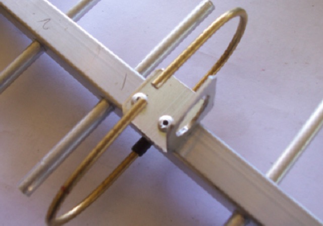
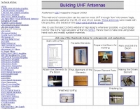 This method of construction can be used on most UHF through \"low\" microwave Yagis, and is especially useful for the 33, 23 and 13 cm bands
 -
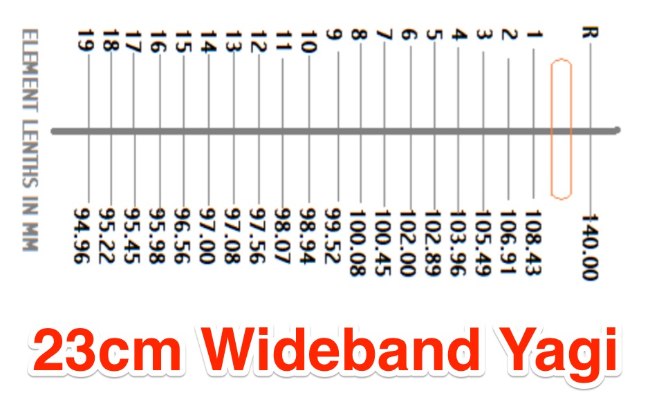
 An interesting presetnation full of usefull tricks to correctly design and build 23 cm Yagi using simple tools. The basic design of the antenna presented in this document is taken from the original DL6WU Yagi Design published in 1982
 -
 Plans for building your own 3-element beam for use on 6m.
 -
 23cm 1296 MHz Field Day Yagi Construction, a 26 element conventional-style design. Article with several pictures and detailed homebrewing instructions
 -
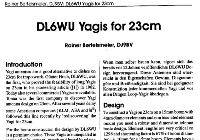 Dubus article about DL6WU long yagi antennas for 23 cm band Article is both in german and english. Yagi antennas are valid alternative to dishes for troposcatter operations. This article explains design and mechanical data for 1296 MHz Yagi Antennas
 -
 Antennas for the 1296 MHz based on the construction plans of some Yagis 35 elements by DL6WU, F9FT, DJ9YW. These antennas features a boom of about 3 m and gives a gain of about 17.8 dBd
 -
 This document provides a detailed guide on constructing and mounting a folded dipol for the 146 MHz frequency in a vertical configuration to be used in Yagi antennas. The step-by-step instructions and diagrams included make it easy for hams to build and set up this type of antenna. Understanding and implementing this design can enhance the performance of radio communication for Amateurs operating in the 2-meter band. Whether you are looking to improve your signal strength or experiment with antenna designs, this resource offers valuable insights and practical information.
 -
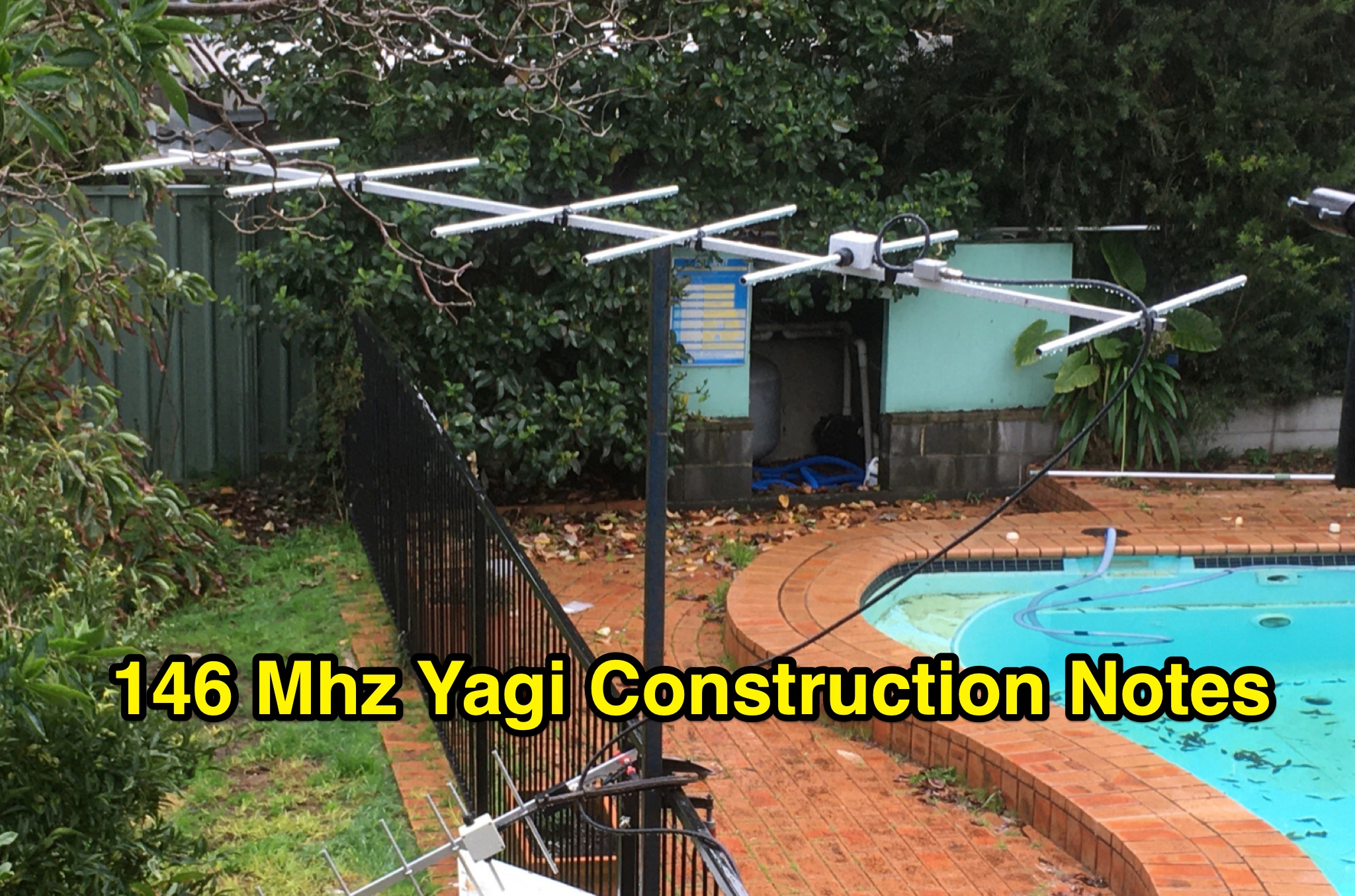 This PDF document contains construction notes for a Yagi antenna designed for the 146 Mhz frequency range. It provides detailed instructions and information on how to build the antenna, making it a valuable resource for hams looking to improve their radio setup. The document covers the materials needed, step-by-step construction process, and tips for optimizing performance. Whether you are a beginner or an experienced ham radio operator, these construction notes can help you enhance your antenna system for better communication.
 -
 145 MHz is the target frequency for this 2-meter Skeleton Slot Yagi Stack antenna project. The design focuses on feeding two stacked Yagi antennas using a skeleton slot radiator, which is a unique approach for VHF enthusiasts. The project details the construction process, including the loop tapered matching section for impedance matching, ensuring optimal performance. The use of specific components like the EH789 element holder and MB456 main mast bracket is highlighted, providing clarity on the assembly process. The construction utilizes 20x20 box aluminum bar for durability and precision. Key dimensions, such as the element length (ER-ED4) and main boom spacing (MM123), are meticulously outlined. This attention to detail aids in replicating the antenna design accurately. The downloadable PDF offers comprehensive instructions, making it accessible for amateur radio operators interested in VHF antenna construction. This project is particularly beneficial for those looking to optimize their 2-meter band operations. The inclusion of a skeleton slot radiator and loop tapered matching section demonstrates advanced techniques in antenna design, catering to both intermediate and advanced builders.
 -
 The W6PQL 23cm Beacon Project describes a **1296 MHz** beacon designed for microwave propagation studies and equipment testing, capable of 30 watts output. It utilizes a PIC 16F628A microcontroller to generate CW and FSK keying for a crystal oscillator, followed by a series of frequency doublers and triplers to reach the target frequency. The final power amplification stage employs a Mitsubishi M57762 module, providing a robust 10-watt RF output. The design emphasizes stability and reliability for continuous operation, with the microcontroller code, written in assembly, provided for customization of the beacon's callsign and message. Originally located in CM97am and aimed at 140 true, the beacon used four 4-foot Yagis stacked vertically for a total ERP of 3kW. The article includes schematics, parts lists, and construction notes to guide builders, along with antenna pattern measurements. Although the beacon itself is no longer in service as of August 2010, the detailed documentation remains a valuable reference for amateur radio operators interested in building similar **microwave** projects or understanding beacon operation.