Search results
Query: 3 ele beam
Links: 126 | Categories: 1
Categories
-
 Details the construction of a **multiband vertical** antenna, specifically designed for stealth operation in a rented property, covering 80m, 60m, 40m, and 30m. The author, N3OX, leverages a 12m Spiderbeam telescoping fiberglass pole as the primary support, noting its sturdiness compared to typical fishing rods while remaining light enough for quick deployment and takedown. The radiating element is a 14 gauge Flex-Weave wire, attached to the pole's top with a rubber grommet, and fed by 27 bare 18 gauge radials spread across a 40-foot square backyard. N3OX describes the impedance matching solution, opting for custom-built L-networks over a remote tuner to enable fast bandswitching. Using an MFJ-259B and EZNEC modeling, base impedances were measured and component values calculated with G4FGQ's L_TUNER and SOLNOID_3 programs. The 80m coil is wound on a 3.5-inch PVC form, while the 30m, 40m, and 60m coils are air-wound, self-supporting #10 wire. Variable capacitors are incorporated for 40m and 30m shunt elements, with the 60m impedance matched by a series inductor. The project includes a **servo-controlled** homebrew band switch, utilizing a two-pole 12-position ceramic wafer switch for remote operation, addressing the limited 80m bandwidth. The entire matching network is housed in a weather-resistant shelter constructed from lumber and aluminum flashing. N3OX reports good DX results at 100W, estimating the total cost between $150 and $250, depending on existing parts.
 -
 Plans for 3 elements beam antenna and gamma matches
 -
 For radio amateurs considering homebrew antenna projects, this resource details several designs from WE6W, an experienced operator. It covers the construction and characteristics of a _160 Meter QRP Loop Antenna_ optimized for high voltage, along with standard and folded variations of the double bazooka antenna. The site also presents a unique Field Day antenna design and instructions for building a Sterba Curtain, a directional array known for its gain. Each design includes practical insights from the author's building experience. The author provides comparative data, such as the performance of a standard bazooka against a traditional dipole, offering real-world context for antenna selection. The Sterba Curtain section includes notes on its beamwidth and gain, crucial parameters for directional operation. These designs are suitable for hams looking to experiment with cost-effective, high-performance antennas for various bands and operating scenarios, from QRP on 160m to directional DXing with a Sterba Curtain, which can offer significant forward gain, often exceeding **10 dB**.
 -
 40 Meter 2 element full size parasitic delta loop wire beam construction and switchable
 -
 4 Element Cubical Quad, Yagis, LZA Circular Quad, Shrunken Quad , quarter wave, J-Pole, beam mounting , changing polarity
 -
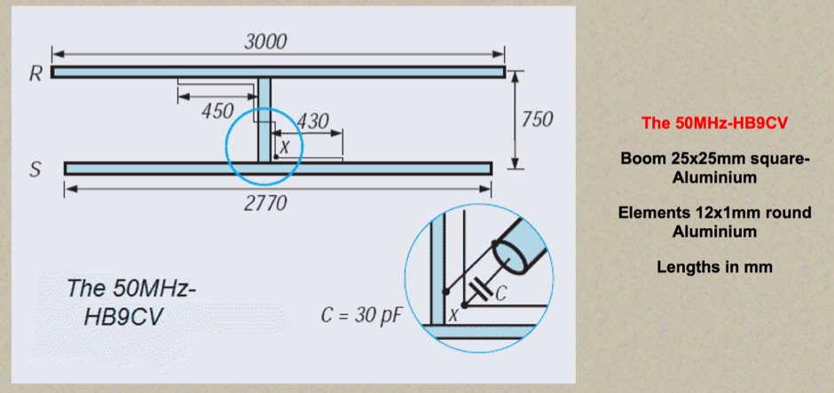 The HB9CV-Beam is a 2-Element-Yagi with two driven elements and was introduced by Rudolf Baumgartner, HB9CV in the 1950ies. This beam antenna is a coax-feeded version of the ZL-Special construction by DK7ZB for 2m, 6m and 10m
 -
 Details the construction and optimization of antenna systems for amateur radio satellite operations, focusing on practical, homebrew solutions for VHF/UHF bands. It covers building _groundplane antennas_ from salvaged materials, recycling old beam antennas into new configurations like a 2-meter crossed yagi, and constructing a 10-meter horizontal delta loop. The resource also explains antenna matching techniques, including folded dipole driven elements and quarter-wave transformers, along with the importance of accurate SWR measurements and minimizing coax loss. Demonstrates how to achieve a **1:1 SWR** by carefully trimming elements and adjusting radial angles on groundplane antennas. It provides insights into selecting appropriate coax and connectors, highlighting the benefits of Belden 9913 for low loss and the proper installation of _N-connectors_. The article also addresses RFI mitigation from computer birdies and presents a design for a silent triac antenna control circuit, offering practical solutions for common satellite station challenges.
 -
 A wire yagi antenna for 20 and 40 meters band suitable for outdoor and field day operations
 -
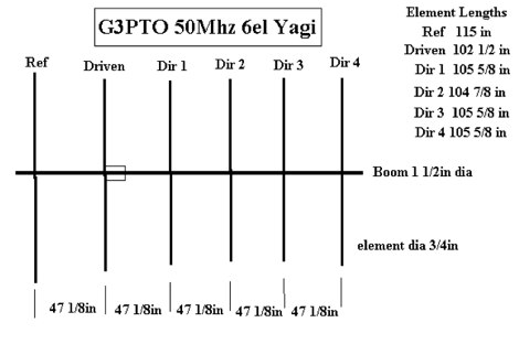 G3PTO antenna drawing plan for a 50MHz 6 Element Yagi beam
 -
 Pictures and plans of a 4 elements yagi beam antenna for 14 Mhz
 -
 This page details the construction of a biquad antenna. The biquad antenna is easy to build, and provides a reliable 11dBi gain, with a fairly wide beamwidth.
 -
 The page provides detailed information about the construction of a full-size 160M 3 element beam antenna and an 80M 5 element beam antenna on a 330ft tower. It includes specifics about the tower height, types of antennas, elements, gain, take off angles, front-to-back ratio, operating frequencies, weight, and dimensions of the beams. The content is aimed at amateur radio operators interested in building high-performance antennas for the 160M and 80M bands. This Antenna is now been destroyed and is no more operational.
 -
 5 Elem. yagi for 10 meters, 9 element yagi beam antenna for six meters band by ON4ANT
 -
 Selecting an appropriate antenna system for shortwave broadcasting involves evaluating various types based on performance, cost, and operational parameters. This resource details the critical specifications for broadcast antennas, including average and peak power ratings, directivity, takeoff angle (TOA), horizontal beamwidth, and gain, emphasizing that a 100-kW transmitter requires an antenna rated for 150 kW average and 400 kW peak. It clarifies that low TOA signals travel thousands of kilometers, while high TOA is for local coverage, and nearly all modern shortwave broadcast antennas are horizontally polarized. The article explores specific antenna types, such as Log-Periodic Antennas (LPAs), which offer wide frequency ranges (e.g., 2-30 MHz) and directional patterns with 11 dBi gain, costing from $20K to over $100K for multi-curtain versions. Dipole arrays, also known as curtain antennas, are prevalent in international broadcasting, featuring steerable beams (±15° and ±30°) and mode-switching capabilities to alter TOA, with high/low pairs costing over $1 million. Fan dipoles are noted for omnidirectional patterns, smaller size, and lower cost for low-power applications, while rhombics, though simple, require resistive termination and incur several dB of I2R losses. Balun considerations are crucial, as most communications baluns are not rated for the higher average and peak powers of AM broadcast transmitters. Modern shortwave antennas utilize durable materials like Alumoweld wire rope for radiators and support elements, avoiding copper, fiberglass, or materials prone to stretching or deterioration. Feeder systems for high-power stations often require tapered-line baluns to convert 50-ohm unbalanced power to 300-ohm balanced for connection to the antenna.
 -
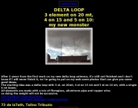 A 3 element DELTA LOOP on 20 meter, 4 on 15 and 5 on 10: my new beam (Just some good ideas)
 -
 This article describes the construction of a Moxon rectangle antenna for the 70MHz (4-meter) amateur radio band. This compact two-element beam design features folded element ends, reducing its width to approximately 75% of a half-wavelength. The antenna was built using enamelled copper wire stretched over a lightweight fiberglass kite spar frame, with a direct coaxial cable feed connection. Initial testing showed a VSWR of around 1.3 with distinct nulls at 90 degrees when horizontally mounted. The author later tested vertical polarization and suggested that the antenna's compact size might allow for indoor loft installation.
 -
 A helically wound two element 40 meter yagi beam antenna from a 1974 QST article
 -
 This Multiband Cubical Quad antenna a boomless Quad design with glass-fibre arms and a single coax wire connected to a remote antenna switch. This aerial work on 8 bands and has a 60-degree beam width. Despite achieving critical technical requirements, the antenna's three-dimensional structure presents obstacles, such as installation issues on fixed towers and risk of frost damage. The spider framework is built of stainless steel, with a compact 18-inch boom and strong angle iron arms. Tait use a variety of methods to fasten element wires and suggests placing them on the outside of the spreaders for improved insulation. The use of nylon twine or parachute cord between key attachment points allows for adjustable separation between pieces.
 -
 Interesting article on mobile antennas by Cebik. . The article offers advice for setting up and operating mobile antennas for ham radio use. It emphasizes the lossy nature of mobile-in-motion antennas but encourages users to rise to the challenge. Steps include safeguarding car electronics, choosing proper cabling, and carefully selecting and mounting antennas. It highlights potential issues like roof mounting, trunk lip grounding, and side-mounting for trucks. For stationary operation, options like dipoles or beams are explored, with safety tips for masts and guying systems. Lastly, it stresses safety, suggesting stopping the vehicle to operate whenever possible
 -
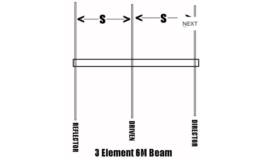
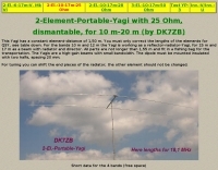
 A homemade antenna plan for a portable yagi beam antenna for the Six meters. Consist of a 3 elements yagi beam design include antenna dimensions, with elements lenght and spacing.
 -
 A 40 meter band two elements yagi beam with a 6mt boom with pictures and drawings
 -
 This wire-beam has one radiator-element, feeded with 450-Ohm-Wireman-twinlead and needs an antenna-tuner. For the bands 6m, 10m, 12m, 15m, 17m and 20m bended reflector-elements are used. The support is a cross of 4 fibreglass-fishing-rods
 -
 The W8JK is a famous and effective DX antenna, first built by John Kraus, W8JK, in 1937. A Beam antenna with two parallel dipoles driven with opposite phase, with a close spacing of an eighth of a wavelength.
 -
 A homebrew project for a 2 meter 4 element yagi beam antenna by 2E0HTS
 -
 A 3 element yagi beam for 40 meters band
 -
 Simple gain antennas for the beginner, a 2 element HF yagi antenna
 -
 This is a hex beam designed for six meters. It has three elements with a turning radius of 54 inches. This antenna can be built from low cost materials available from the local hardware store. By WB3BEL
 -
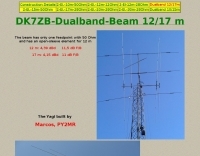 The beam has only one feedpoint with 50 Ohm and has an open-sleeve element for 12 m by DK7ZB
 -
 8 and 4 elemets yagi beam antenna by N6CA
 -
 F6DED page of a 2 element beam W8LK antenna with pictures and dimensions, in french
 -
 Details a practical QRP wattmeter construction, leveraging a simplified SWR meter design by JA6HIC. The project focuses on a forward-only power measurement circuit, providing a functional instrument for RF power levels from milliwatts up to 5 watts. It maintains a 50-ohm input and output impedance, suitable for typical QRP transceivers and antenna systems. The resource includes the schematic for the "VSW" (Very Simple Wattmeter) and outlines a six-step alignment procedure. This calibration process involves using a known RF source up to 5W, setting full-scale deflection, and marking power increments. It also addresses minimizing frequency effects on readings with a 100pF trimmer capacitor, noting that measurement error is highest at the lower end of the scale. Construction notes mention using a piece of RG-213 coaxial cable for the inductance and coupler, with the wattmeter assembled in early 2003. The author provides an example measurement showing 0.8W into a dummy load and 1W into a 3-element beam.
 -
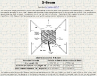 Two element X-Beam is a high-performance broad-band antenna that is ideal for Ham radio operators with limited space. X-Beams are inexpensive and easy to build. The performance of the simple X-beam is amazingly similar to larger, more conventional antennas by 4S7NR
 -
-
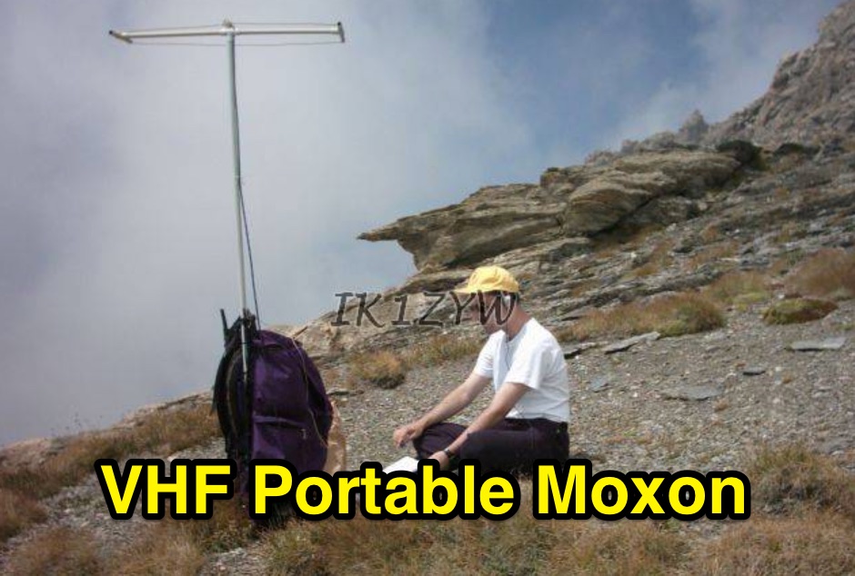 An easy to build moxon antenna for portable use. A Moxon Rectangle is a two element beam, where both elements are folded towards eachother.
 -
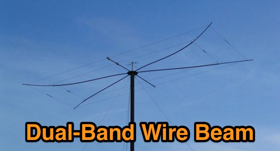 The Dual-Band Wire Beam was inspired by L.B. Cebik's (W4RNL) article The Elusive Moxon Nest. Fiberglass tubing spreaders, Flexweave elements, an aluminum hub, and two die-cast aluminum flanges combine to provide a 12/17m Moxon nest with one 50 ohm feed.
 -
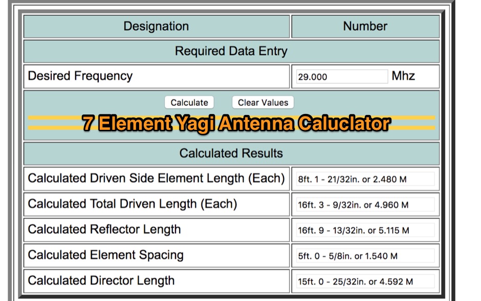 Online javascript antenna calculator designed to give the critical information of a particular beam antenna, in this case a seven element Yagi, for the frequency chosen.
 -
 A javascipt online calculator for 2 and 3 element beam antennas. Just input frequency and will diplay element dimensions and spacing. Measurements in Feet and Meters by G4VWL
 -
 The document details the optimization and construction of the _Maria Maluca_ antenna, a compact 6-band (20m-6m) directional beam. It presents a comparative analysis of shortwave antenna principles, highlighting the efficiency gains achieved by using an open feeder line and tuner as a resonant unit, contrasting this with the losses associated with traps or capacitive loads in multiband antennas. The resource specifically revisits an older South American 2-element design for 10, 15, and 20 meters, applying modern NEC-based software to develop a six-band version. Performance data is meticulously tabulated, showing impedance, free space gain, gain at 12m height, elevation angle, and front-to-back (F/B) ratio for each band from 20m through 6m. For instance, on 15m, the antenna achieves 5.1 dBd free space gain and 13.72 dB F/B ratio. The construction section provides practical guidance on element assembly using aluminum pipes and hose clamps, detailing the use of a heavy-duty glass fiber reinforced polyamide rod for electrical separation and bending strength. It also specifies the use of 450-ohm _Wireman_ line CQ 552 for the transmission line. The document includes diagrams for rod fixing, an air-wound balun, and a vertical elevation diagram for the 15m band, illustrating its DX qualification. It also discusses the antenna's suitability for portable and expedition operations, noting its compact transport dimensions (max 1.50m length, 12 lb weight) and quick assembly time (under 15 minutes). The author, Dipl.Ing. Helmut Oeller, DC6NY, is identified as a source for material kits.
 -

-
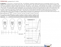
 This Yagi has a constant element-distance of 1,50 m. You must only correct the lengths of the elements for QSY, see table down. For the bands 10 m and 12 m the Yagi is working as a reflector-radiator-Yagi, for 15 m and 17 m as a beam with radiator and director.
 -
 A 7 elements yagi beam monoband antenna for 14 Mhz by VE3GK
 -
 The Charles Gizmotchy high performance horizontal and vertical beam antennas. Two, Six, Ten and eleven meters antennas
 -
 Managing extensive amateur radio contact logs efficiently requires specialized software that integrates various operational aspects. Aether provides a macOS-native logging solution, designed from the ground up using Apple's Cocoa, to streamline QSO entry, organization, and retrieval for Mac users. It supports modern macOS technologies and offers an intuitive interface, aligning with the user experience expected on Apple platforms. The application includes features such as automatic dupe checking, which quickly identifies previous contacts with a station, and awards tracking, indicating if a new contact is needed for specific operating awards. Aether also integrates rig control via RS-232, automatically populating frequency, mode, and power data from supported Elecraft, Icom, Kenwood, Yaesu, and some TEN-TEC transceivers. This automation reduces manual entry errors and speeds up the logging process. Furthermore, Aether offers comprehensive QSL management, including synchronization with eQSL.cc and Logbook of The World, and the ability to print QSO detail and address labels for paper QSLs. It also incorporates automatic callbook lookup from sources like QRZ.com and HamQTH.com, and calculates distance and beam heading, with Google Maps integration for visualizing contact locations. Full ADIF and Cabrillo import/export capabilities ensure compatibility with other logging software and contest submission platforms.
 -
 A compact Beam Antenna That Can Be Built At Home. Made with lightweight wooden "X" frame with two folded and linear loaded wire elements. The two elements are approximately a half-wave each.
 -
 JJ0DRC's HF multi-band delta loop antenna project, initially conceived during the waning peak of Cycle 23, addresses the common challenge of achieving effective DX operation from a small residential lot in Japan. Dissatisfied with a ground plane antenna's performance in SSB pile-ups, the author sought a beam-like solution without a tower, drawing inspiration from a JJ1VKL article in CQ Ham Radio Sep. 2000. The antenna, constructed in October 2000, employs two 7.2-meter fishing rods (37% carbon fiber, reinforced with cyano-acrylate glue and aluminum tape) and 1mm enameled wire, fed by an Icom AH-4 external antenna tuner. While the exact beam pattern remains unmeasured, JJ0DRC observed a significantly higher callback rate compared to dipole antennas, particularly on higher bands. The system's circumference length of 15-20m is crucial for maintaining a good beam pattern across HF bands, though performance on lower bands like 80m, 40m, and 30m becomes less directional as the length deviates from a full wavelength. Ongoing maintenance addressed degradation issues, including aluminum tape cracking and wire breakage at connection points due to strong winds (often exceeding 10-15m/s in winter). The author reinforced rod connections with IRECTOR PIPE SYSTEM components and INSU-ROCK ties, and improved wire attachment methods using Cremona rope and epoxy bond to enhance durability.
 -
 Design for a 5 element beam on a 23 foot boom with an unusual combination of performance characteristics
 -
 Presents a comprehensive guide for constructing a broadband Hex Beam antenna, a popular directional array for HF operation. This design offers a compact footprint and excellent gain characteristics, making it suitable for limited space installations while providing significant performance advantages over omnidirectional antennas. The resource details the specific dimensions for a five-band Hex Beam covering 20, 17, 15, 12, 10, and 6 meters, emphasizing the critical element spacing and wire lengths required for proper resonance and pattern. It outlines the construction of the center post, spreaders, and wire elements, along with the feed point assembly, ensuring proper impedance matching. The project aims for a forward gain of approximately **5.5 dBi** on most bands, with a front-to-back ratio often exceeding _20 dB_. Building this antenna requires careful measurement and assembly, but the resulting performance provides a substantial upgrade for DXing and contesting.
 -
 A two elements beam antenna tunable from 6 to 20 meters, based on the Maria Maluca antenna project by DB9EX, in german
 -

-
 Here is an antenna for the nineties. It's strong, computer designed, and has lots of gain. It is a full size, four element beam on 10, and three elements on 15 meters