Search results
Query: 3 element 20m
Links: 40 | Categories: 0
-
 40 Meter 2 element full size parasitic delta loop wire beam construction and switchable
 -
 10-12-15-17-20m A description was in the German Ham-Magazine "Funkamateur" in Issue 11/2003
 -
 Demonstrates the construction and performance of an updated ZS6BKW multiband dipole, a variant of the _G5RV_ antenna, specifically designed for HF operation. The article details a real-world installation using 13.5m copper wire elements and 12.2m of 450 Ohm ladder line, configured as a sloping inverted-V with the apex at 10m and ends at 4m above ground. It covers the critical aspect of impedance matching, incorporating an 8-turn choke balun at the feedline transition to RG-58U coax to mitigate RF common mode current. Measurements confirm favorable SWR readings below **1.3:1** on 7.1 MHz, 14.11 MHz, 18.06 MHz, and 24.8 MHz, indicating effective resonance across 40m, 20m, 17m, and 12m bands. The installation also shows usable SWR dips on 3.55 MHz (5:1), 29.02 MHz (2:1), and 50.84 MHz (3:1), extending its utility to 80m, 10m, and 6m with an antenna tuning unit. Initial on-air results report clear reception of stations over **5000km** away, validating its DX potential.
 -
 The **NW3Z** optimized wideband antenna designs, originally presented at Dayton 2001, detail Yagi configurations for the 20-meter, 15-meter, and 10-meter amateur radio bands. This resource provides access to the design files, likely containing critical parameters such as element spacing, element lengths, and boom dimensions, which are essential for replicating these directional antennas. The designs focus on achieving wide bandwidth, a desirable characteristic for contesters and DXers operating across a significant portion of each band. The content specifically references "nw3z-Antenna-DesignsDownload," indicating that the core information is available as a downloadable file, presumably in a format suitable for antenna modeling software or direct construction. Such files typically include **NEC models** or similar data, allowing for performance analysis and optimization before physical construction. The emphasis on "optimized wideband" suggests design considerations for SWR bandwidth and gain characteristics over a broader frequency range than typical narrow-band Yagis. The resource serves as a direct source for specific, proven antenna designs from a known amateur radio antenna designer, offering practical data for hams interested in building high-performance Yagi arrays for HF.
 -
 This wire-beam has one radiator-element, feeded with 450-Ohm-Wireman-twinlead and needs an antenna-tuner. For the bands 6m, 10m, 12m, 15m, 17m and 20m bended reflector-elements are used. The support is a cross of 4 fibreglass-fishing-rods
 -
 F6EZX presents a detailed account of constructing a compact, multi-band _Levy antenna_ for portable holiday operations, specifically addressing issues with local QRM from a previous _Deltaloop_ setup. The article outlines the design criteria, including multi-band operation on 40m, 30m, 17m, 15m, 12m, and 10m, a symmetrical configuration to reduce interference, and a low take-off angle for DX. Construction involves 2x 10.3m radiating elements and a 15.3m open-wire feeder (ladder line) with 7cm spacing, made from 1.5mm2 copper wire and foam pipe insulation spacers. Theoretical calculations, referencing F9HJ's "_Les antennes Levy_" book, guide the determination of element lengths and feeder impedance characteristics, aiming for a good match across bands with a commercial antenna tuner. Initial field tests with the _VCI Vectronics VC300DLP_ tuner showed a 1:1 SWR from 80m to 10m, with some difficulty on 17m. The antenna, mounted as a 45-degree slopper with the high point at 12m, successfully facilitated DX contacts to South America, particularly Chile and Argentina, suggesting a lower take-off angle compared to the previous Deltaloop which favored Brazil. The Levy antenna significantly reduced TVI/RFI, attributed to its improved symmetry and greater distance from the QRA. While signal reports on 15m and 20m were 1-2 S-points lower than the Deltaloop, its performance on 40m and 30m was comparable, fulfilling the design goals for a portable, low-cost, multi-band solution.
 -
 A rotary trapped-dipole for 17 and 20 meters, as described by IZ7ATH, presents a practical solution for multi-band HF operation. The author, Talino, recounts his experience building this antenna for IK7ZCQ, detailing the evolution from an initial concept involving a grounded-driven element and gamma-match to a direct-fed, non-grounded design. His pragmatic approach, adapting available materials, is evident throughout the construction narrative, particularly with the use of eight tapered aluminum pipes for the driven element. Construction specifics include precise measurements for the aluminum tubing, with diameters ranging from 30 mm down to 16 mm, and a critical note on reducing tip thickness for weight optimization. The _traps_, initially a concern, are fabricated using 8 turns of RG58 coax on a 27 mm support, tuned to resonate at 18.1 MHz using a dip-meter. Talino emphasizes sealing the traps with RF glue and PVC tape to prevent water ingress, a crucial step for longevity. Field test results, conducted on a 10-meter pole in a clear garden environment, showed an SWR of 1.2:1 on 17 meters and 1.5:1 at 14.200 MHz. While SWR varied slightly when installed at Mario's QTH due to nearby objects, the antenna's performance remained commendable. The final half-dipole length is 46 cm for the 18 MHz tips, and the total weight is under 6 kg, with potential for further reduction.
 -
 A simple to build Yagi 2 element antenna for 15 or 20 meters band by 9m2mso
 -
 An homebrew project for a 3 elements yagi monoband antenna for the 20 meters by 9M2MSO
 -
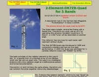
 The document details the optimization and construction of the _Maria Maluca_ antenna, a compact 6-band (20m-6m) directional beam. It presents a comparative analysis of shortwave antenna principles, highlighting the efficiency gains achieved by using an open feeder line and tuner as a resonant unit, contrasting this with the losses associated with traps or capacitive loads in multiband antennas. The resource specifically revisits an older South American 2-element design for 10, 15, and 20 meters, applying modern NEC-based software to develop a six-band version. Performance data is meticulously tabulated, showing impedance, free space gain, gain at 12m height, elevation angle, and front-to-back (F/B) ratio for each band from 20m through 6m. For instance, on 15m, the antenna achieves 5.1 dBd free space gain and 13.72 dB F/B ratio. The construction section provides practical guidance on element assembly using aluminum pipes and hose clamps, detailing the use of a heavy-duty glass fiber reinforced polyamide rod for electrical separation and bending strength. It also specifies the use of 450-ohm _Wireman_ line CQ 552 for the transmission line. The document includes diagrams for rod fixing, an air-wound balun, and a vertical elevation diagram for the 15m band, illustrating its DX qualification. It also discusses the antenna's suitability for portable and expedition operations, noting its compact transport dimensions (max 1.50m length, 12 lb weight) and quick assembly time (under 15 minutes). The author, Dipl.Ing. Helmut Oeller, DC6NY, is identified as a source for material kits.
 -
 An homemade portable vertical antenna with a trap near the mid point of the main element. The trap is made with 42mm diameter PVC pipe with 9 turns of wire on it
 -
-
 The ZS6BKW wire antenna, a variant of the G5RV, utilizes a specific 13m (42.6 ft) length of 450-ohm window line as its matching section, feeding a 28.5m (93.5 ft) flat-top element. This design aims for lower SWR on 40m, 20m, 17m, 12m, and 10m compared to a standard G5RV, often achieving SWR values below 1.5:1 on these bands without an antenna tuner. The feedpoint impedance transformation provided by the window line allows for direct connection to 50-ohm coax on multiple bands. F4FHH's experience involved constructing the ZS6BKW and evaluating its performance against an _OCF dipole_ (Off-Center Fed) on various HF frequencies. The article includes observations on SWR readings and operational effectiveness, highlighting the ZS6BKW's suitability for multi-band operation. The antenna's overall length, including the flat-top and window line, is approximately **41.5 meters** (136 feet), making it a significant wire antenna for fixed station use. Comparative analysis with the OCF dipole provided practical insights into the ZS6BKW's advantages and limitations, particularly concerning bandwidth and tuner requirements.
 -
 Demonstrates the product line of _LZ Antenna Ltd._, a Bulgarian manufacturer specializing in amateur radio antennas and custom electronic devices. The company focuses on robust, high-quality HF multiband Yagi and vertical antennas, leveraging over 20 years of experience from founder Georgi Georgiev in radio amateur development. Featured models include the LZA 8-4, LZA-10-3, and the LZA-7-3A WRTC 2022, alongside various rotary dipoles like the LZA1 40/30m. Provides specifications for several Yagi antennas, such as the LZA-9-5, LZA-13-7, and LZA-6-3 (a 6-element, 3-band design). The company emphasizes applying "leading edge technology" to high-frequency communication equipment production, with products designed for durability and performance. The LZA-10-5 Yagi offers **12.5 dBi** gain on 10m, while the LZA-13-7 provides **13.2 dBi** on 20m, showcasing competitive gain figures for DXing and contesting.
 -
 An antenna originally planned in the sixties, a two element beam antenna tunable on several band, in french
 -
 Demonstrates the design and construction of a compact, portable multi-band mini-delta loop antenna, specifically optimized for /P (portable) operations from remote locations like Scottish islands. The resource covers the theoretical underpinnings of half-wave loops, contrasting closed and open configurations, and then details the application of a folded dipole principle to achieve a 50-ohm match for direct coax feed. It presents empirical formulas for calculating element lengths, considering the velocity factor of common wire types, and provides a detailed example for a 20m (14.175 MHz) version. The article includes a comprehensive table of dimensions and allowances for a five-band (20m, 17m, 15m, 12m, 10m) mini-delta beam, along with construction hints for the central support and balun. It specifies a 1:1 trifilar balun wound on a ferrite rod and describes the antenna adjustment process using an _MFJ-259B Antenna Analyser_. Initial test results indicate an SWR of 1:1 at resonance and a bandwidth of approximately 240 kHz on 20m, even at a low height of five feet above ground. The distinctive utility lies in its focus on a practical, easily deployable beam antenna for portable DXing, offering a viable alternative to more complex or larger arrays.
 -
 Construction details and tests about a 2 elements cubical quad antenna for HF Bands (20,17,15,12 and 10m band).
 -
 A 5 element wide spaced yagi for the 20m long path to Europe was installed at ZL6QH, the antenna is fed with a 600 ohm open wire feed line.
 -
 Demonstrates the construction and implementation of a **two-element phased vertical array** for 40 meters, utilizing _Christman phasing_ techniques. The author, W4NFR, details the process from building individual 1/4-wave aluminum verticals to integrating them into a phased system. The resource covers antenna spacing of 32 feet, elevated radial design, and the critical steps for tuning each vertical to achieve a 1.1:1 SWR before combining them. It also provides insights into calculating precise coax lengths for feedlines and the phasing delay line, emphasizing the use of an MFJ-269 Antenna Analyzer for verification. The finished system exhibits good front-to-back nulls, with an overall SWR ranging from 1.6:1 to 2.2:1, which is managed by an antenna tuner. The project includes detailed photos of the relay box, showing 12 VDC relays capable of handling 5KV, and the control box in the shack for switching between three different antenna pattern configurations. Static bleed-off chokes are incorporated for protection, and the construction emphasizes robust weatherproofing for outdoor elements.
 -
 A compact 2 element W8JK beam antenna for 20M to 10M bands by AF6SA
 -
 Designing and constructing portable wire antennas for HF operations, this resource explores several configurations including the _foldback dipole_ for space-constrained setups and an inductively shortened dual-band dipole for 20m and 40m. It details the calculation of inductance for shortened elements, providing a Visual Basic 6.0 program screenshot that illustrates determining coil parameters like turns and length for a **25.5 uH** inductor. The document emphasizes practical considerations such as adjusting wire lengths for optimal SWR, noting that a dual-band dipole achieved SWR below 2:1 on both 20m and 40m, with careful adjustment bringing it under 1.5:1. Further, the resource describes a half-wave antenna matched with a coaxial stub, a method often referred to as the _Fuchskreis_ in German amateur radio circles, to transform the high feedpoint impedance to 50 Ohms. This monoband solution, for a 20m application, uses a stub length of **2.98m** (0.216 lambda multiplied by coax velocity factor) and a shorted stub of approximately 48cm. The coaxial stub design is highlighted for its resilience to ground proximity, allowing it to be rolled up or laid on the ground with minimal SWR impact, making it highly suitable for portable QRP operations.
 -
 Based on a simple project based on a 2 elements Yagi for 20m band, and then becomed a triband yagi with a open-sleeve feed system
 -
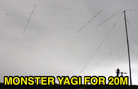
 This antenna was designed for the CQ WW CW 2009 at EA8URL. All elements are made out of fishing rods with an insulated copper cable fixed on the rods by cable ties. Both fishing rods and cable are UV resistant.
 -
 A 2 elements delta loop antenna for 14 MHz with a MMana simulation file, dimensions, pictures of this aluminium tube based delta loop antenna, and matching system details.
 -
 The dipole shown in this document is installed in an inverted Vee configuration, with two leg elements on each side held parallel to each other by 21cm spacers. The upper leg is for 40m and the lower leg for 20m. The spacers are made of 7mm plastic garden hose support for garden sprayers cut to 21cm.
 -
 A delta loop antenna for 20 meters band designed with MMana with a tuning system made in a classic stub configuration
 -
 Designing and constructing a two-element receiving loop antenna array for HF operation involves specific considerations for achieving high directivity and noise reduction. This resource details a homebrew system comprising two 30-inch diamond-shaped loops, spaced 20 feet apart, which are fed through mast-mounted preamplifiers and passive signal combiners. The operational principle relies on adjusting phase delays between elements via precise _Belden 8241_ coaxial cable lengths, optimized for specific bands from 160m to 20m. Performance data, derived from _EZ-NEC_ modeling, illustrates consistent 90° azimuth-plane beamwidth and low take-off angles across the target bands, with _Receiving Directivity Factor_ (RDF) values comparable to a 300-foot Beverage antenna. The article presents detailed elevation and azimuth plots for 20m, 30m, 40m, 80m, and 160m, demonstrating the array's ability to provide strong response at low DX angles while also supporting _NVIS_ signals. Key components like the _DX Engineering RPA-1_ preamplifier and _DXE RSC-2_ signal combiner are discussed, alongside the importance of impedance matching to preserve antenna patterns. The construction emphasizes self-contained elements that do not require ground radials, offering a compact solution suitable for suburban environments and stealth installations, with a focus on optimizing receive performance independently from transmit antennas.
 -
 Constructing an End-Fed Half-Wave (EFHW) antenna offers a practical solution for HF operators seeking a multiband wire antenna without the need for extensive radial systems. This design typically employs a high-impedance transformer at the feed point, matching the antenna's inherent high impedance to a 50-ohm coaxial feedline. The article specifically details a 2012 approach, focusing on a transformer with a 49:1 turns ratio, which is a common configuration for EFHW antennas. The resource outlines the construction of a wire element cut for a half-wavelength on the lowest desired band, with specific coil arrangements enabling operation on harmonically related bands such as 40m, 20m, and 10m. It discusses the physical dimensions and winding details for the matching transformer, often utilizing a ferrite toroid core to achieve the necessary impedance transformation. The content provides insights into the operational principles and practical considerations for deploying such an antenna, including methods for tuning and optimizing performance across multiple amateur radio bands. While acknowledging that the presented information from 2012 may be superseded by newer insights, it serves as a foundational reference for understanding EFHW antenna theory and construction.
 -
 A 20-meter window frame stealth antenna, based on a design by _PD7MAA_, utilizes a single 620cm wire loop for discreet installation. The feeding mechanism employs a _4C65_ toroidal core, where the antenna loop functions as a single-turn secondary, and the feedline wraps twice. Tuning is achieved via a 30cm twisted wire stub, allowing for SWR adjustment within the 20m band. This design is specified for QRP operation, with a maximum power limit of **25 Watts** to prevent core saturation or arcing. Wire selection recommendations include thin, insulated copper wire (0.75mm to 1mm) for blending with architectural elements. The guide focuses on practical construction steps for a low-profile 14MHz antenna.
 -
 Documents S21RC's construction of an impedance transformer harness for a VHF/UHF cross yagi, utilizing 20m of _RG179_ cable. Details the creation of a DIY RF sampler with a -50dB sampling output, primarily for measuring HF radio PA section output with a Spectrum Analyzer, also applicable for _Pure Signal_ transmission. Chronicles the deployment of a 200m long beverage antenna for the _S21DX IOTA_ operation in 2022, positioned 2m above ground. Discusses the construction of a 3-element short beam for 10m to replace a previous 2-element antenna, with assistance from S21DW. Provides guidance on operating cheap _PA-70_ and _PA-100_ type Chinese SSPAs using IRF530 MOSFETs, emphasizing the necessity of a final LPF. Outlines the design and construction of a fully isolated interface for radio-to-computer connections, supporting various digital modes with isolated ground, audio transformers for IN/OUT, optical isolation for CAT/CIV, and isolated PTT/COS lines. Includes a log of software updates, such as the _HMI/TFT for NX8048K070_ and _2.1.14 Lite_ release with bug fixes for PEP hold and gradual watt decay.
 -
 Constructing a dual-band antenna for 40 and 20 meters often involves compromises in size or complexity. This resource presents a compact _open sleeve dipole_ design that addresses these challenges by using 450-ohm ladder line and folded elements to achieve a total length of approximately **17.17 meters**, significantly shorter than a full-size 40-meter dipole. The design leverages electromagnetic coupling, where a primary radiator handles the 40-meter band, and a second conductor resonates on 20 meters without direct electrical connection. This configuration eliminates the need for traditional traps, loading coils, or switching components, simplifying construction and reducing potential loss points. The antenna is fed with RG-58C/U coaxial cable, and a common-mode choke is recommended at the feed point to suppress sheath currents, ensuring a cleaner radiation pattern and minimizing RF in the shack. The design is well-suited for portable operations, field deployments, temporary installations, and restricted urban environments where space is a premium, offering solid performance on both HF bands.
 -
 A mircovert antenna assembled for the 40m version of the DL7PE antenna. A one meter long aluminum tube with 24mm diameter is used for the base (element 1) and a 50cm aluminum tube with 20mm diameter for element 2 (the extention). A pvc pipe, 34cm long and with a diameter of 38mm, is used to wind the coil on (1mm enamelled copper wire).
 -
 The PAC-12 Antenna, a multi-band portable vertical, is meticulously detailed in this construction article by James Bennett, _KA5DVS_. The design emphasizes ease of homebrewing using readily available components from local hardware stores, including replaceable loading coils. It outlines the preparation of the 72-inch telescoping whip (originally from Radio Shack, with an alternate source now provided by _Pacific Antenna_), the construction of the loading coils from PVC risers, and the fabrication of the aluminum rod base sections. Specific instructions cover threading aluminum rod with a _1/4-20 threading die_ and assembling the feedpoint insulator with a BNC connector, along with recommendations for radial deployment. KA5DVS, an avid traveler and QRP enthusiast, developed the PAC-12 to address the bulkiness of random wire setups and the limitations of commercial portable antennas like the Outbacker or SuperAntennas MP1. His goal was a lightweight, packable antenna that disassembles into 12-inch sections, achieving an assembled length of approximately 8 feet. The design strategically places the loading coil away from the base for improved efficiency. The PAC-12 notably placed first in efficiency compared to a quarter-wavelength wire vertical at the HFPack antenna shootout during the Pacificon conference in October 2001, demonstrating its practical performance for field operations. Appendix C showcases various _NJQRP Club_ members' PAC-12 constructions, including a 20m beam made with multiple PAC-12 elements.
 -
 A Lightweight 2m Yagi for SOTA. The boom is 20mm PVC electrical conduit and the elements are 2.4mm aluminium TIG welding rod. The antenna is carried as a single length of conduit with the elements stowed inside the boom, sealing them in with a bung. The driven element is connected directly to 50 Ohm coax with a BN-43-202 balun core to decouple the coax shield.
 -
 A coaxial cable trap is a fundamental component in multiband antenna design, enabling a single radiator to resonate efficiently on multiple frequencies by electrically shortening or lengthening the antenna element. This project focuses on constructing such a trap for a vertical antenna operating on the 10 MHz (30m) and 14 MHz (20m) amateur bands, providing practical insights into its fabrication and integration. The article outlines the specific dimensions and winding techniques for the coaxial trap, emphasizing the use of readily available materials. It details the physical construction of the vertical element, including the mast and radiating sections, to achieve optimal performance across both target bands. The author shares personal experiences with similar trap designs, noting their effectiveness in previous horizontal dipole configurations. Key construction steps are illustrated with _original photos_, showing the assembly of the trap and its incorporation into the overall antenna structure. The design aims for a compact footprint, making it suitable for limited space installations while still delivering effective DX capabilities on the **30-meter** and **20-meter** bands.
 -
 a 20M quarter-wave vertical antenna with a 6m telescopic mast, 1:1 balun, and spiral-wound driven element. Designed for QRP at 14.285 MHz, the antenna’s performance exceeded expectations, delivering low SWR and surprisingly quiet reception. Initial testing yielded successful contacts with European stations and EC1KR, showcasing its effectiveness. Compact and easy to deploy, the antenna promises to be an excellent portable solution for future hilltop operations.
 -
 The Butternut HF2V, originally a two-band vertical antenna for 80m and 40m, was enhanced by the user to include 30m and 20m bands for better digimode DX work during the solar minimum. The additions used components adapted from the HF6V and innovative methods for the 20m addition, either through a parallel vertical element or a lower-mounted independent element, minimizing band interaction. This modified four-band antenna now supports high power across popular HF bands using a single feedpoint.
 -
 This project details the design and construction of a Spider Quad antenna for HF bands (20m, 17m, 15m, 12m, and 10m). The boomless structure optimizes driver and reflector spacing, enhancing performance. Tuning and impedance matching were refined using antenna analyzers and a 1:2 balun. Final tests confirmed excellent SWR and gain, making this an efficient solution for top performance DXing.
 -
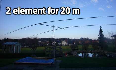
 This article discusses the design and implementation of a 2-element wire beam antenna for the 20 meter band, suitable for field day operations with 4 Switchable Directions. The antenna is configured with sloped wires in an inverted V shape, with a specific design to achieve directional properties. The author tested the antenna design using MMANA and NEC2 software, based on a solution published in QST. Detailed diagrams and instructions are provided for constructing the antenna on top of a 12 meter mast, with specific wire lengths and positioning to ensure optimal performance. This resource is valuable for hams looking to build a directional antenna for the 20m band and improve their field day setup.
 -
 Guide to constructing an effective antenna for 50MHz. Inspired by a design from Martin DK7ZB, the article emphasizes the importance of precise measurements and quality materials. With a 2.20m boom and careful assembly, the antenna promises excellent performance, resilience, and cost-effectiveness, making it ideal for six meter band operations.