Search results
Query: 40 meter band 2 element
Links: 37 | Categories: 0
-
 Build a space efficient trapped dipole antenna for 40-80-160 meter bands using RG-58 and PVC pipe. The document provides a brief guide on building a compact dipole antenna appropriate for the 40, 80, and 160-meter amateur radio bands. It explains the materials, building processes, and tuning methods required to provide best performance while preserving space. The paper also discusses theoretical elements of dipole antennas, such as impedance matching and feedline selection.
 -
 The RXO Unitenna, a vertical wideband antenna, offers operation across the 7-21 MHz spectrum, covering the 40, 30, 20, 17, and 15-meter amateur bands. This design focuses on achieving a low SWR across a broad frequency range, making it suitable for general HF operation without requiring an external antenna tuner for minor SWR variations. The antenna utilizes a unique loading coil and matching network to maintain efficient radiation characteristics across its operational bandwidth. Construction details within the PDF document include specific dimensions for the radiating element and the counterpoise system, which is critical for vertical antenna performance. The design incorporates readily available materials, simplifying the build process for radio amateurs. Performance graphs illustrate the SWR characteristics across the 7 MHz to 21 MHz range, demonstrating the antenna's wideband capabilities. The document also provides guidance on feedline connection and grounding considerations for optimal field deployment. This vertical antenna configuration is particularly useful for hams with limited space, offering a compact footprint compared to horizontal wire antennas.
 -
 A wire yagi antenna for 20 and 40 meters band suitable for outdoor and field day operations
 -
 Demonstrates the construction and on-air performance of the _NB6Zep_ antenna, a modified 20-meter Extended Double Zepp design optimized for multi-band operation from 40 through 10 meters. The resource covers basic design principles, including dimensions of 66 feet horizontal and 5 feet vertical elements, and specifies open ladder line or TV twin lead for the transmission line. It details material selection for low-cost wire antenna construction, such as 18 AWG wire for the legs and ceramic or plastic insulators, along with practical tips for soldering connections and insulating against moisture. The author, NB6Z, shares insights from extensive _EZNEC_ modeling to optimize the antenna's total length for a 40-meter half-wave dipole footprint and feed line length for direct tuner connection. The article presents field results, including successful _PSK31_ contacts from Oregon to the East Coast on 40 and 30 meters with 50 watts, even at a low height of 6 feet. It provides detailed performance characteristics for each band, noting the _NB6Zep_'s highest gain (over 3 dB) and sharp, medium-angle lobes on 20 meters, which yielded strong DX reports to locations like Korea, Japan, and Argentina. For 17 and 15 meters, it describes a butterfly-like pattern with broad lobes, while 12 and 10 meters exhibit narrow, directional lobes in an "X" configuration. The author also shares personal experiences operating successfully for over a decade in an antenna-restricted environment using the NB6Zep and other stealth wire antennas.
 -
 The Bruce array is a simple, often-forgotten wire antenna array that is advantageous for 80 and 160 meters, where typical gain antennas are very large. This bi-directional broadside vertical array is only 1\4 lambda high and does not require a ground system. It offers substantially greater SWR bandwidth than the half-square or bobtail curtain. A 4-element Bruce array used by N6LF showed a gain of about 4.6 dB compared to a 1\4 lambda vertical with 8 elevated radials, with a 2:1 SWR bandwidth greater than 400 kHz. The antenna is simple and its dimensions are flexible.
 -
 The total length of this antenna is 41m, height is about 11m, and diameter of element is 2mm. JA7KPI modified this antenna originally used as Inverted-V type of 80m band Dipole. Works on 40 - 80 meters band with acceptable swr.
 -
 The 30/40 meter **vertical antenna** project by IK4DCS details the construction of a shortened, self-supporting design, reaching a total length of 5 meters. The antenna incorporates a linear loading section and a coaxial cable trap for 30 meters, based on the "Antenne Volume 2°" text by Nerio Neri (page 223). The design uses six radials, three for each band, positioned at approximately 90° inclination and at least one meter above the roof or ground, connected via a 1:1 balun at the feed point. Mechanical construction utilizes aluminum tubing, with a 2.30-meter primary radiator section (30 mm diameter) joined to a second part using a Teflon insert and a PVC sleeve for rigidity. The linear load, approximately 3.70 meters long, accounts for a 30% physical shortening of the quarter-wave element. A capacitive load, made from three 50 cm radials, is integrated into the 40-meter top section for fine-tuning. Final adjustments involved radial inclination for 40 meters, as initial testing showed increased SWR and interference on 30 meters due to nearby resonant structures. The author emphasizes the importance of clear space for optimal performance and provides drawings and photos to clarify the build process.
 -
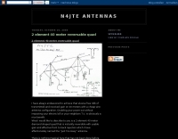 A reversable quad antenna for 40 meters band by N4JTE
 -
 A 40 meter band two elements yagi beam with a 6mt boom with pictures and drawings
 -
 A 3 element yagi beam for 40 meters band
 -
 W5ALT Indoor Vertical Antenna is a base loaded vertical antenna that can be tuned on almost all HF bands by adjusting a big coil. Operating a ham radio station from an apartment in Maracaibo, Venezuela, the author demonstrates effective communication with over 100 countries using a custom-built indoor vertical antenna. Addressing common misconceptions, the design uses a balanced approach with radials and a base-loaded vertical element made from affordable materials. The antenna fits discreetly indoors, covers 6 to 40 meter bands, and achieves acceptable SWR with an MFJ tuner. Despite limited space and typical apartment challenges, the setup enables reliable DX contacts, confirmed by numerous QSL cards, proving indoor antennas can perform well in constrained environments.
 -
 This PDF document, authored by KT4QW in October 2004, details the construction and modeling of a dual-band, horizontally polarized hanging rectangular loop antenna for **10 and 17 meters**. The design, adapted from *The ARRL Handbook*, utilizes _NEC4WIN95_ software for scaling and optimization, targeting a 50 ohm feedpoint impedance. The resource includes a bill of materials, step-by-step construction instructions, and a discussion of the antenna's radiation characteristics. It presents NEC-generated elevation and azimuth patterns, comparing the loop's performance to a half-wave horizontal dipole at the same height and frequency. The 17-meter element is centered at 18.140 MHz for low SWR across the phone band, while the 10-meter element is centered at 28.500 MHz. Construction involves 14-gauge stranded copper wire and Schedule 40 PVC spreaders, with the total wire length calculated by the formula: Length in feet = 1005/MHz. The feedpoint impedance can be adjusted by modifying the rectangular aspect ratio. The document specifies hoisting the antenna to at least a half-wave above ground for testing. It notes that a balun was tested and found to have no measurable effect on SWR or radiation characteristics. A 2-meter scale model is presented to illustrate the physical design, and a "rotator" string is incorporated for directional adjustment up to 90 degrees.
 -
 The document discusses a two-element parasitic Delta-Loop array for the 40 meters band, aimed at radio amateurs interested in antenna projects. It provides detailed plans and instructions for building a homemade Delta-Loop antenna.
 -
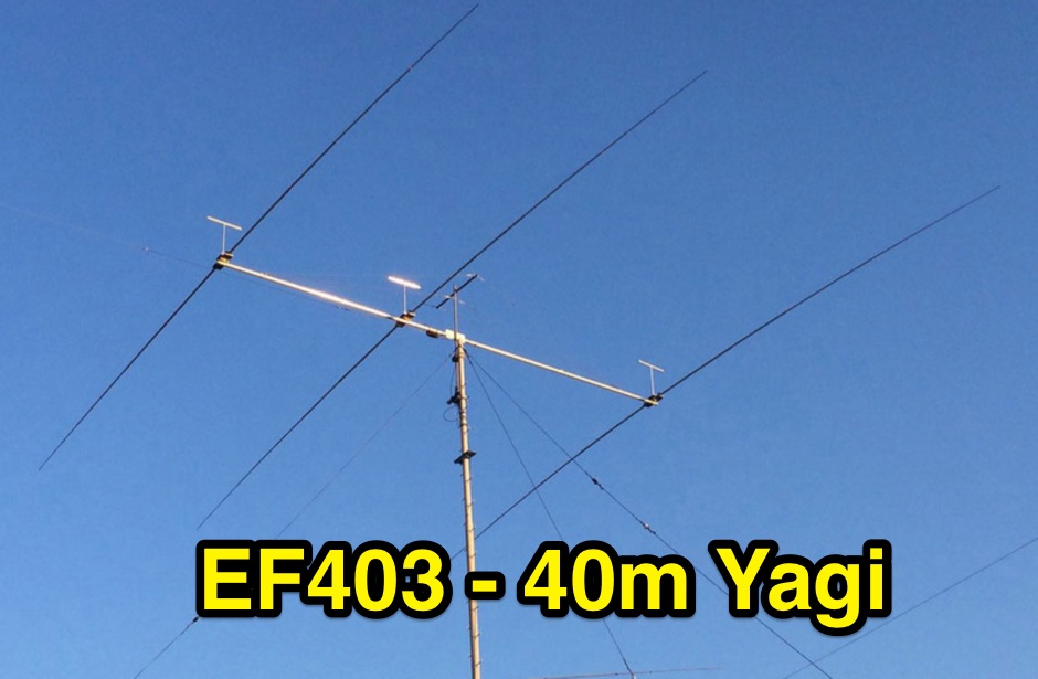 EF403 is a 3 element yagi antenna for the 40 meters band with high gain and F/B Ratio
 -
 This project outlines the construction of a 3-element reversible quad antenna specifically designed for the 40-meter band. The materials required include pushup towers, pressure-treated posts, insulated wire, and various electrical components such as relays and a balun. The construction process is straightforward, beginning with the installation of the posts in a straight line, followed by the assembly of the antenna elements and their elevation to the desired height. The antenna's design allows for directional signal reception, making it ideal for operators looking to enhance their communication capabilities on the 40-meter band. The project includes detailed instructions on tuning the antenna for optimal performance, ensuring that operators can achieve the lowest SWR possible. Additionally, the design can be adapted for other bands by extrapolating dimensions, providing versatility for amateur radio enthusiasts. Overall, this reversible quad antenna project is suitable for both beginners and experienced operators, offering a practical solution for improving signal strength and directionality in 40-meter communications.
 -
 The ZS6BKW wire antenna, a variant of the G5RV, utilizes a specific 13m (42.6 ft) length of 450-ohm window line as its matching section, feeding a 28.5m (93.5 ft) flat-top element. This design aims for lower SWR on 40m, 20m, 17m, 12m, and 10m compared to a standard G5RV, often achieving SWR values below 1.5:1 on these bands without an antenna tuner. The feedpoint impedance transformation provided by the window line allows for direct connection to 50-ohm coax on multiple bands. F4FHH's experience involved constructing the ZS6BKW and evaluating its performance against an _OCF dipole_ (Off-Center Fed) on various HF frequencies. The article includes observations on SWR readings and operational effectiveness, highlighting the ZS6BKW's suitability for multi-band operation. The antenna's overall length, including the flat-top and window line, is approximately **41.5 meters** (136 feet), making it a significant wire antenna for fixed station use. Comparative analysis with the OCF dipole provided practical insights into the ZS6BKW's advantages and limitations, particularly concerning bandwidth and tuner requirements.
 -
 Operating a ZS6BKW antenna often involves understanding its lineage from the _G5RV_ design, with specific modifications by ZS6BKW to optimize performance on several bands. Through computational analysis and field measurements, the antenna's dimensions were refined to allow operation on 10, 12, 17, 20, and 40 meters without an antenna tuner. For 80, 30, and 15 meters, a tuner is necessary, though efficiency on 30 and 15 meters is noted as not particularly high. The physical configuration consists of two 13.755-meter radiating elements fed by a 12.20-meter section of 450-ohm ladder line. Tuning the antenna on the 20-meter band is critical, and any deviation in the ladder line's characteristic impedance necessitates recalculating the element lengths. The design is also referenced in the 12th edition of _Rothammel's Antennenbuch_, page 219. Proper common mode current suppression is crucial at the transition from ladder line to coaxial cable. This can be achieved with a common mode choke, such as several turns of coax wound into a coil or over a ferrite toroid like an Amidon T130. While a 1:1 balun is an option, it may introduce issues.
 -
 Presents a construction project for a linear-loaded 40-meter rotatable dipole, detailing the design evolution from mid-element coils to 300-ohm twinlead loading. It covers material selection, including repurposed fishing poles and EMT conduit, and outlines the assembly process for the antenna elements and mounting plate. The resource provides specific measurements for element lengths and linear loading sections, along with SWR plots demonstrating the antenna's resonance at 7.035 MHz with a 1.1:1 SWR, and bandwidth up to 7.120 MHz below 2:1 SWR. The article documents the antenna's performance during various RTTY and CW contests, including the SARTG RTTY and SCC RTTY contests in August 2006, and the ARRL DX CW and CQWW WPX RTTY contests in February 2007. It reports successful operation at 500-1000W, noting improved performance after replacing a faulty coax cable. Specific DX contacts from British Columbia, including stations in Europe and South Africa, are listed, illustrating the antenna's capability despite its shortened length and relatively low height of 55 feet. The content highlights practical considerations such as weatherproofing the connections and supporting the fiberglass elements to prevent sagging. It also includes a brief comparison to an inverted-V at similar height and a ground-mounted vertical, noting the rotatable dipole's quieter reception. The author shares insights into the iterative design process and tuning adjustments made to achieve optimal resonance.
 -
 Presents the design and performance of a 4-element wire Yagi antenna for the 40-meter band, building upon VE3VN's earlier 3-element switchable wire Yagi. The resource details the antenna's evolution, highlighting the transition from a 3-element to a 4-element configuration and the resulting improvements in gain and front-to-back ratio. It provides specific insights into the antenna's construction and expected operational characteristics. VE3VN shares insights from field results, noting the antenna's performance on 40 meters. The discussion includes the antenna's pattern and matching characteristics, crucial for any DXer or contester looking to optimize their signal on this popular HF band. The author's experience with the previous 3-element design informs the enhancements made to this 4-element iteration. The article includes a visual representation of the antenna's current view, offering a practical perspective on its physical layout. It serves as a valuable reference for hams considering a directional wire antenna for 7 MHz operations, demonstrating a practical approach to achieving enhanced directivity and gain.
 -

-
 An inverted triangle Delta Loop Antenna for the 40 meter band made with aluminium pipes, each element is 14,2 meters including a home made aluminium mount.
 -
 This project details the construction of a **full-sized 40-meter vertical antenna**, born from a renewed interest in 7 MHz operation and a desire for improved effectiveness over simple dipoles. The author, K5DKZ, initially focused on VHF experimentation, which provided an inventory of aluminum tubing and fiberglass spreaders for this endeavor. Before this vertical, K5DKZ utilized an 80/40 meter inverted-vee trap dipole and a 40-meter broadband dipole, but now primarily uses a pair of full-sized, phased, quarter-wave verticals spaced 35 feet apart for serious 40-meter work. The construction involves a base-heavy design for stability, using a 44.5-inch section of 1-1/4 inch steel TV mast driven into 1-3/8 inch aluminum tubing, insulated by a 105-inch section of Schedule 40 PVC pipe. The assembly reaches 31 feet, close to the 32 feet required for a quarter-wavelength on 40 meters, with fine-tuning achieved by winding wire onto a fiberglass spreader. The design is explicitly presented as a foundation for a two-element 40-meter Yagi beam, outlining modifications like substituting aluminum for steel in the base and using an inductive hairpin match for the driven element. The article also discusses tuning considerations for a large 40-meter beam, noting the 100 to 200 kHz upward frequency shift when raised, and suggesting methods for installation on a tower. The author emphasizes the cost-effectiveness and good performance of the monopole approach, especially when multiple verticals are needed.
 -
 An homebrew project for a 3 element coil-loaded Yagi beam antenna for 40 Meter band
 -
 Demonstrates the adaptation and construction of a 7-element DK7ZB Yagi antenna for the 4-meter band (70 MHz), utilizing components from a defunct 2-meter CUE DEE Yagi. The resource details the modifications made to the original DK7ZB design to fit the shorter CUE DEE boom length, specifically adjusting element lengths for 6mm rod elements while reusing existing mounting holes for the reflector and last director. It provides precise element lengths for the reflector, dipole (12mm aluminum tube), and five directors, along with a note on cutting elements for transport. The article includes a 4NEC2 simulation file for performance analysis and an SWR plot, confirming the antenna's electrical characteristics. It also specifies the calculation for the quarter-wavelength matching cable using SAT752F coaxial cable, resulting in a 909mm length. Practical application is shown with the finished antenna in operation at JO20XC, listing several activated Maidenhead squares such as JO56PA and JP40KS, validating its effectiveness for portable 70 MHz operations.
 -
 A 2 element 40 meters band parasitic delta loop antenna project with pictures and details
 -
 Designing and constructing portable wire antennas for HF operations, this resource explores several configurations including the _foldback dipole_ for space-constrained setups and an inductively shortened dual-band dipole for 20m and 40m. It details the calculation of inductance for shortened elements, providing a Visual Basic 6.0 program screenshot that illustrates determining coil parameters like turns and length for a **25.5 uH** inductor. The document emphasizes practical considerations such as adjusting wire lengths for optimal SWR, noting that a dual-band dipole achieved SWR below 2:1 on both 20m and 40m, with careful adjustment bringing it under 1.5:1. Further, the resource describes a half-wave antenna matched with a coaxial stub, a method often referred to as the _Fuchskreis_ in German amateur radio circles, to transform the high feedpoint impedance to 50 Ohms. This monoband solution, for a 20m application, uses a stub length of **2.98m** (0.216 lambda multiplied by coax velocity factor) and a shorted stub of approximately 48cm. The coaxial stub design is highlighted for its resilience to ground proximity, allowing it to be rolled up or laid on the ground with minimal SWR impact, making it highly suitable for portable QRP operations.
 -
 The page discusses the concept of a 2-element Parasitic Ground Plane antenna for the 40-meter band. It includes a conversation between amateur radio operators discussing modeling results and design considerations for the antenna. The author shares insights on radial configurations and the impact on antenna efficiency and pattern.
 -
 An easy to build and extremely high performance antenna, works perfectly on all HF bands 3.5-28 MHz with some compromises, it is basically an half wave dipole for 40-80 meters, an LC circuit or trap 40 meters allows you to use a single radiating element.
 -

-
 A multiband Fan Dipole that works on 40 20 15 meters band, making a folded dipole for 7 MHz band and additional element for the 21 MHz and 14 MHz
 -
 Constructing a dual-band antenna for 40 and 20 meters often involves compromises in size or complexity. This resource presents a compact _open sleeve dipole_ design that addresses these challenges by using 450-ohm ladder line and folded elements to achieve a total length of approximately **17.17 meters**, significantly shorter than a full-size 40-meter dipole. The design leverages electromagnetic coupling, where a primary radiator handles the 40-meter band, and a second conductor resonates on 20 meters without direct electrical connection. This configuration eliminates the need for traditional traps, loading coils, or switching components, simplifying construction and reducing potential loss points. The antenna is fed with RG-58C/U coaxial cable, and a common-mode choke is recommended at the feed point to suppress sheath currents, ensuring a cleaner radiation pattern and minimizing RF in the shack. The design is well-suited for portable operations, field deployments, temporary installations, and restricted urban environments where space is a premium, offering solid performance on both HF bands.
 -
 A 3 band dipole antenna for 40-80-160 meter bands, It's made with easily available materials and is designed for inverted V mounting. The antenna is shortened for these bands, but still manages to make contacts in 80m and 160m with stations in Canada and the USA. The construction details are provided, including the dimensions of the antenna elements and the traps. The antenna is easy to build and provides good performance in all three bands. In Italian.
 -
 The longest element has a total length of 14m and has a boom length of 5.5 meters featuring a total bandwith of 166 kHz
 -
 The author describes his experience building and using a Beverage antenna for the 40-meter band. Despite encountering some challenges, the antenna offered some improvements in receiving stations compared to a 3-element inverted Vee antenna. The Beverage antenna showed a significant daytime signal-to-noise ratio improvement and received signals better than the Vee antenna. However, the front-to-back ratio was not ideal, and the transmit power seemed to affect the Beverage antenna. Overall, the author concludes that the Beverage antenna might be more suitable for locations with higher noise levels. The total cost of the antenna was around 30 Euros.
 -
 The tri-band trapped delta loop antenna design operates on 80 meters (3.5–4 MHz), 40 meters (7–7.3 MHz), and 30 meters (10.1–10.15 MHz) using a single triangular wire loop. This configuration eliminates the need for an external antenna tuner or band-switching relays. The antenna's physical perimeter, approximately 270 feet, establishes 80M as the fundamental band, with specific trap placements enabling resonance on 40M and 30M. Trap design and placement are critical, with 30M traps positioned inboard of 40M traps within the horizontal element. Each slant leg measures approximately 80 feet. The resource references foundational information from the _ARRL Antenna Handbook_ and _ON4UN’s Low Band DXing_ regarding full-wave loop behavior and feedpoint impedances. The project aims to provide multi-band HF operation from a single, fixed antenna structure.
 -
 This page discusses the construction and design of a shortened 2-element Yagi antenna for the 40-meter band, focusing on the driven element. The author shares insights on adding hats to the coil to reduce losses and improve performance. The article also mentions the use of EZNEC modeling software and an AIM4170 analyzer for tuning. Amateur radio operators interested in such antenna design and optimization for the 40-meter band can find useful information and practical tips on this page.
 -
 VE1ZAC's analysis details the performance of **MFJ927** and **SGC239** autotuners with portable HF vertical antennas, specifically comparing 31 ft and 43 ft configurations. The resource originated from challenges encountered during a Maritime QSO Party roving operation, necessitating a lightweight and easily deployable antenna system. Target bands for the contest included 80, 40, 20, 15, and 10 meters, with a maximum power handling of 100 W CW. The author utilized a 30-foot carbon fiber push-up pole to support a vertical wire element, noting its 2 lb weight and reliability. EZNEC modeling was employed to predict performance, showing favorable results for a 30-foot vertical with elevated radials, particularly on 40 and 20 meters. Feedpoint impedance measurements, taken with an AIM4170C, are presented for various HF bands, both with and without a 41-foot RG6 stub designed to reduce reactance on 80 and 20 meters. The stub significantly improved matching on these bands, easing the tuner's workload. Operational tests revealed issues with the MFJ927's reliability during contest setup, leading to reliance on the K3's internal tuner. The SGC239, tested post-contest, performed flawlessly. A detailed side-by-side comparison covers mechanical aspects, connection options, power bias, impedance range, board quality, and documentation. Modifications to the MFJ927, including a new aluminum case, white paint for heat reduction, and upgraded impedance-measuring resistors, are also described.