Search results
Query: 70 vertical
Links: 31 | Categories: 0
-
 An Easy Dual-Band VHF/UHF vertical Antenna made with a TV twin lead and coax cable
 -
 How to Build a Dual-Band Antenna for 2M/70cm presentation PDF file
 -
 Presents the KE4UYP linear-loaded vertical antenna design, which introduces very little loss on 80 or 160 meters, achieving an overall radiation efficiency of 80% to 85%. This design addresses common pitfalls of traditional base-fed verticals by placing the majority of the current at the top of the antenna, eliminating the heavy reliance on extensive ground radial systems. The author's initial 10-meter model, only three feet tall, yielded 5/9 signal reports to Anchorage, AK, and Europe, confirming its effectiveness. The antenna incorporates both vertically and horizontally polarized radiators, with a 1/4 wavelength horizontal counterpoise located at the feed-point, near the top, to create an almost totally omnidirectional pattern with high wave angle horizontally polarized radiation. This dual polarization ensures even illumination across all take-off angles, making it effective for both local contacts and **DXing**. The vertical element is linear loaded, adding capacitance reactance and making it longer than the horizontal element to achieve resonance and raise the feed-point impedance to 50 ohms. Fine-tuning the antenna requires careful adjustment, as tower reactance can vary. The article suggests starting with 80 feet for 80m and 170 feet for 160m for the vertical wire, then trimming for resonance. Bandwidth specifications include 300 kHz under 2:1 **SWR** on 80m and 100 kHz on 160m when suspended between trees, or 150 kHz on 80m when side-mounted on a tower.
 -
 Multi Band Quad,Cushcraft R5, R7, R7000, repair and maintenance, Remote Antenna Switching, Hexagonal Beam, Automatic Band Decoder, Low Band Verticals, Crank-up Tiltover Tower etc
 -
 The Flower Pot Antenna project details a portable dual-band antenna primarily operating on 10 meters, with secondary resonance near the 30-meter band. Construction involves winding RG58 coaxial cable uniformly around a large plastic flower pot, approximately 70cm high with a 60cm top diameter. The design eliminates the need for radials, contributing to its compact and lightweight nature. Key construction steps include soldering the inner conductor to the shield at one end of the wound cable and connecting the wound cable's shield to the rig cable's inner conductor at the base. An LC network, comprising a variable capacitor (0-200pF) and an inductor (10 coils, 5cm diameter, 2mm wire), is inserted between the wound cable's inner conductor and the rig cable's shield. Tuning is performed with an antenna analyzer, adjusting cable length and the variable capacitor for optimal impedance on 10 meters. The antenna performs effectively when installed horizontally.
 -
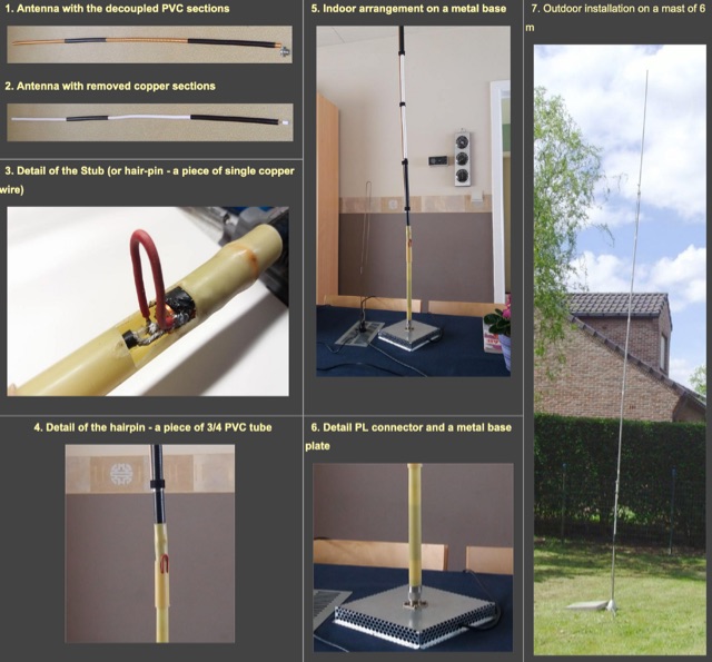
 This project details three variants of a vertical half-wave antenna design for the 4-meter (70MHz) amateur radio band. The antennas use end-feeding with a parallel-tuned circuit for impedance matching to 50-ohm coaxial cable. The first variant uses suspended flexible wire for portable use, the second employs a fiberglass rod with internal wire for permanent outdoor installation, and the third utilizes aluminum tent poles for quick mobile deployment. Despite the narrow bandwidth of the matching circuit, this suits the narrow 4m FM allocation well. The design offers an effective omnidirectional radiation pattern and can be constructed with readily available materials.
 -
 The 30/40 meter **vertical antenna** project by IK4DCS details the construction of a shortened, self-supporting design, reaching a total length of 5 meters. The antenna incorporates a linear loading section and a coaxial cable trap for 30 meters, based on the "Antenne Volume 2°" text by Nerio Neri (page 223). The design uses six radials, three for each band, positioned at approximately 90° inclination and at least one meter above the roof or ground, connected via a 1:1 balun at the feed point. Mechanical construction utilizes aluminum tubing, with a 2.30-meter primary radiator section (30 mm diameter) joined to a second part using a Teflon insert and a PVC sleeve for rigidity. The linear load, approximately 3.70 meters long, accounts for a 30% physical shortening of the quarter-wave element. A capacitive load, made from three 50 cm radials, is integrated into the 40-meter top section for fine-tuning. Final adjustments involved radial inclination for 40 meters, as initial testing showed increased SWR and interference on 30 meters due to nearby resonant structures. The author emphasizes the importance of clear space for optimal performance and provides drawings and photos to clarify the build process.
 -
 This article describes the construction of a Moxon rectangle antenna for the 70MHz (4-meter) amateur radio band. This compact two-element beam design features folded element ends, reducing its width to approximately 75% of a half-wavelength. The antenna was built using enamelled copper wire stretched over a lightweight fiberglass kite spar frame, with a direct coaxial cable feed connection. Initial testing showed a VSWR of around 1.3 with distinct nulls at 90 degrees when horizontally mounted. The author later tested vertical polarization and suggested that the antenna's compact size might allow for indoor loft installation.
 -
 A 20 meter quarter wave vertical antenna by jerry sevick W2FMI QST Article
 -
-

-
 A copper pipe Hentenna for 144 MHz. The Hentenna, a compact, high-gain loop antenna developed in Japan in the 1970s, offers approximately 5.1 dBd gain, comparable to a three-element Yagi. Adapted for 2 meters, it is crafted from copper pipe for simplicity, affordability, and broadband performance. Requiring no feed-point tuning, its construction involves soldering standard copper fittings. Installation demands non-conductive materials to minimize signal disruption. Versatile for vertical or horizontal polarization, it is ideal for FM, repeater, SSB, or CW applications. This design emphasizes practicality and performance for amateur radio enthusiasts
 -
 The antenna is a vertical dipole, around which four parasitic elements are forming a circle.
 -
 NEC4WIN is a 32 bits commercial antenna simulation software based on MININEC3 developed by the Naval Ocean Systems Center in the 70s and 80s. It runs under Windows and can be used to simulate, analyze and optimize wire antennas, beams, verticals, etc. NEC4WIN has limitations. They are the same as Mininec3 on which the engine is based.
 -
 GW4ALG's _136 kHz Pages_ document the evolution of vertical antennas for the 2200m band, starting with a prototype mounted on a house wall. This initial design, despite achieving the first **395 km** GM-GW QSO, suffered from significant insulation breakdown, high RF losses due to proximity to the house, and difficult tuning adjustments. The author details the challenges of maintaining resonance and matching with a variometer in the loft, noting that adding three earth spikes offered no measurable improvement over a simple water tap connection. The subsequent experimental 12m vertical, relocated away from the house, significantly reduced dielectric losses and proved far more effective. This antenna enabled GW4ALG to set a world DX record on 136 kHz with a **1916 km** QSO to OH1TN, and an intra-UK record of **703 km** to GM3YXM/P. The resource further explores the use of helium-filled balloons to extend the vertical radiator, achieving heights up to 27m, typically 20m, for enhanced low-band performance. Practical advice on balloon types, inflation, and critical insulation between the wire and balloon is provided, emphasizing safety and avoiding arcing.
 -
 A vertical monoband antenna design that can work from 6 meters to 70 cm by F5ZV in French
 -
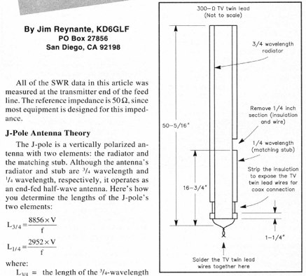
 The resource presents a detailed schematic for constructing a dual-band vertical antenna, specifically designed for operation on the 2-meter and 70-centimeter amateur radio bands. It illustrates the physical layout, critical dimensions, and component placement necessary for successful replication. Key elements such as the radiating elements, phasing sections, and feed point are clearly depicted, providing a visual guide for radio amateurs undertaking a homebrew antenna project. The diagram specifies the lengths for the VHF and UHF sections, indicating how these elements are integrated to achieve dual-band functionality from a single coaxial feedline. It also implies the use of common materials readily available to most experimenters, focusing on simplicity and effectiveness in its design. The visual format of a GIF image ensures direct access to the construction details without requiring extensive textual interpretation. This schematic serves as a practical reference for hams interested in building a compact, efficient vertical antenna for local and regional FM communications, offering a proven design for immediate implementation.
 -
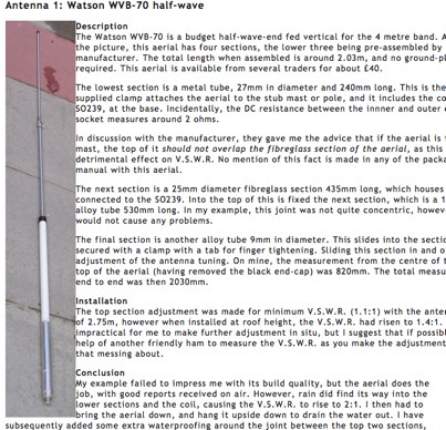
 This article compares two commercial vertical antennas for the 4-meter amateur radio band: the Watson WVB-70 half-wave and the Sirio CX4-71. The Watson measures 2.03m in length, costs around £40, and exhibited adequate performance but required additional waterproofing after rain affected its VSWR readings. The longer Sirio CX4-71 (3.02m) performed noticeably better, delivering signals approximately 2 S-points stronger than the Watson. The Sirio demonstrated high build quality, a stable 1.2-1.4:1 VSWR, and weather resilience, though minor VSWR fluctuations were observed during rain and frost. Both antennas are half-wave designs requiring no ground plane radials.
 -
 The X80 multi-band HF vertical antenna, a commercial iteration of the Rybakov design, exhibits a physical length of 5.5 meters, or approximately 18 feet, and is constructed from aluminum tubing. It operates as a non-resonant vertical, requiring an external antenna tuner for impedance matching across its intended operating frequencies. The antenna's design incorporates a 1:4 UNUN at its base, facilitating a nominal 50-ohm feed point impedance for the coaxial cable. Performance observations indicate effective operation on 40 meters, 20 meters, 15 meters, and 10 meters, with reduced efficiency on 80 meters and 160 meters due to its relatively short electrical length for these lower bands. Comparative analysis with a G5RV dipole and a half-wave end-fed antenna reveals the X80 offers a lower take-off angle, beneficial for DX contacts, particularly on the higher HF bands. Field tests conducted with an Icom IC-706MKIIG transceiver and an LDG AT-100ProII autotuner demonstrate the X80's ability to achieve acceptable SWR across 80m through 10m. The antenna's compact footprint and ease of deployment make it suitable for restricted spaces or portable operations, though its performance on 80 meters is noted as a compromise compared to full-size resonant antennas.
 -
 A 200 kHz bandwidth digital transmission system for image transfer in the Amateur Service is under development, specifically targeting VHF allocations. John B. Stephensen, KD6OZH, leads this project under an FCC Special Temporary Authority (STA) valid until September 10, 2006, authorizing emissions up to 200 kHz bandwidth in the 50.3-50.8 MHz segment. Current regulations typically limit bandwidths to 20 kHz on VHF amateur bands, making this STA crucial for testing wideband digital modes. The modem, a modified **OFDM** (Orthogonal Frequency Division Multiplexed) unit, was initially tested on the 70-cm band. It splits a high-rate data stream into multiple low-rate subcarriers to mitigate multipath echoes. The system uses a DCP-1 card with a Xilinx XC3S400 FPGA and Oki Semiconductor ML67Q5003 microcontroller. The transmitter, located at 36d 46m 30s N, 119d 46m 22s W, generates 150 WPEP into an 8 dBi gain vertical antenna, while the mobile receiver uses a Ham-stick. Three data formats for 50, 100, and 200 kHz channels are being tested, with encoded data rates of 96, 192, and 384 kbps. Verilog code for the VHF OFDM modem is 95% simulated, with modifications from the UHF version including increased filter coefficient precision and a change from Ungerboeck **TCM** to BICM for improved performance over fading paths. Final tests will involve one-way over-the-air measurements of bit error rates and coverage area.
 -
 Operating a ham station often involves encountering radio frequency interference (RFI), RF feedback, or RF burns, which are frequently misattributed to poor equipment grounding. This resource meticulously dissects these assumptions, asserting that RF grounds on the operating desk often merely mask more significant system flaws. It identifies five primary causes for RF problems, including antenna system design flaws, proximity of the antenna to the operating position, DC power supply ground loops, equipment design defects, and poorly installed connectors or defective cables. The content emphasizes that issues like "hot cabinets" or changes in SWR when connecting a ground indicate substantial RF flowing over wiring or cabinets, a phenomenon known as common-mode current. The article provides detailed explanations of common-mode current generation, particularly from single-wire fed antennas like longwires, random wires, and OCF dipoles, which inherently present high levels of RF in the shack. It also illustrates how vertical antennas, lacking a perfect ground system, can excite feed lines with significant common-mode current. Through simulations, the author demonstrates how a dipole without a proper _balun_ can cause RF problems at the operating desk, showing current patterns and voltage distributions on feed line shields. The discussion extends to the proper application of _RF isolators_ and _ferrite beads_, clarifying their role in modifying common-mode impedance on cable shields and cautioning against their use as a band-aid for fundamental system defects. The resource advocates for correcting the actual source of RF problems, such as antenna system issues or poor connector mounting, rather than relying on internal shack grounding or isolators. It highlights that properly functioning two-conductor feed lines, like coaxial or open-wire lines, should result in minimal RF levels at the operating position, even without a desk RF ground. The author shares personal experience, noting that his stations since the late 1970s have operated without RF grounds at the desks, relying instead on proper antenna system design and feed line integrity.
 -
 A presentation of the Yagi Antennas, and other interesting tid-bits by Brian Mileshosky. The document provides an in-depth exploration of the Yagi-Uda antenna, detailing its historical development, design principles, and performance characteristics. Originally described in the 1920s, the Yagi antenna features a driven element and parasitic elements, including reflectors and directors, which collectively determine its behavior. The document highlights how element lengths, diameters, and spacing influence gain, impedance, and directivity. It also discusses the antenna's reciprocal nature and presents data on typical gain values for various element configurations. Additionally, the text covers practical considerations, such as the construction of a "Tape Measure Yagi" for amateur use, and touches on related antenna types like dipoles and their application in Near Vertical Incident Skywave (NVIS) communication.
 -
 Documents the OC1I and OC6I IOTA DXpeditions to Peru, specifically highlighting operations from SA-098 (Isla La Leona) and SA-076 (Isla Lobos de Afuera). The OC1I team logged over **8000 QSOs** from SA-076, while OC6I made 1400 QSOs from SA-098, despite challenging propagation conditions. The resource details the equipment used, including an _IC-7000_, an IC-706mkIIG, and a TS-440SAT, along with various antennas such as a 160m dipole, FD4, G5RV, and a multi-band vertical for 17m, 20m, 30m, and 40m. The DXpedition dates are specified: OC6I operated from SA-098 between December 28 and December 30, while OC1I was active from SA-076 from January 2 to January 7. Both operations are confirmed as valid for IOTA credit. The page also includes a video link for the OC6I operation and a photo gallery from the DXpedition. Feedback is welcomed, and the webmaster is identified as Bodo Fritsche, DL3OCH.
 -
 A travel, or a fixed vertical coax antenna originally designed by PA0FBK. This antenna is very easy to make from a piece of 50 ohm or 75 ohm coaxial cable, and can be either smooth, roll-up version, or rigid cable
 -
 A comparison of commercial 4m verticals by by Ian Hogan G6TGO
 -
 The ZS1J/B beacon operates on 28.2025 MHz with 5 Watts output to a half-wave, end-fed vertical antenna, initially installed in 1977 as ZS5VHF near Durban. The 10-meter transmitter is a modified 23-channel CB radio, and the identification keyer uses a diode matrix unit with TTL ICs from the same era. After relocation to Plettenberg Bay in 1993, the beacon has been in continuous service, with additional QRP transmitters later installed for other bands. In 1994, a single-transistor, 80-meter, 0.5-watt QRP transmitter with a half-wave dipole was added on 3586 kHz, followed by a 160-meter, 0.5-watt unit on 1817 kHz. A 30-meter, 0.5-watt transmitter was installed in 1996, operating on 10.124 MHz. In 2002, a 40-meter QRRP beacon on 7029 kHz, with an output of 100 microwatts, achieved DX reports up to 1100 km from ZS6UT in Pretoria. Best DX reports for the 80m and 160m beacons came from 9J2BO.
 -
 10 Elements Cross-Yagi Antenna for 433 MHz. The base of the 10el antenna is the recalculated RA6FOO antenna.Circular polarization is realized - by a phasing quarter-wave line, matching of horizontal and vertical polarization antennas
 -
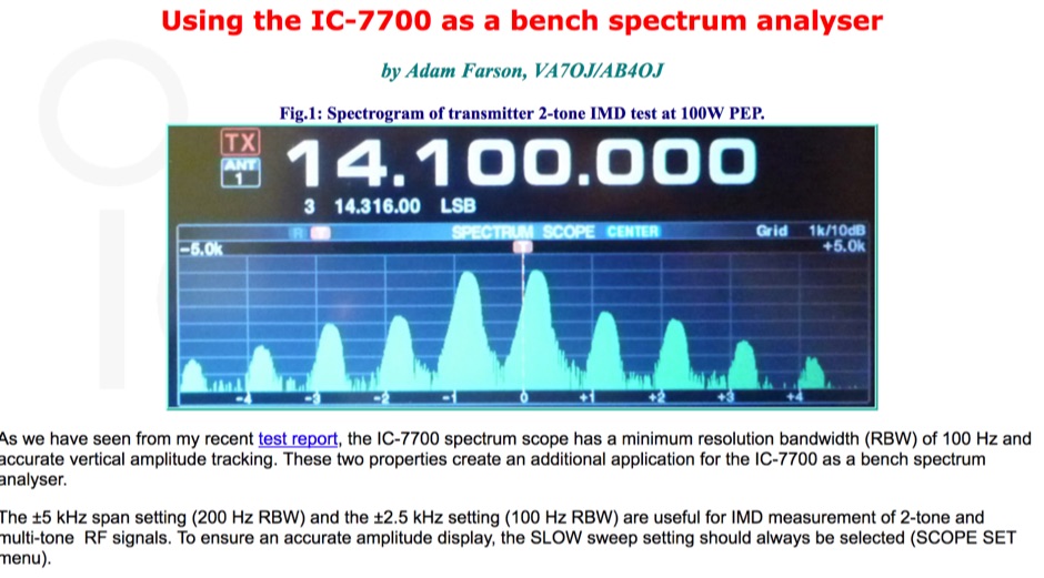 The Icom IC-7700 spectrum scope feature a minimum resolution bandwidth of just 100 Hz and provide also an accurate vertical amplitude tracking permitting to use the 7700 as a bench spectrum analyser.
 -
 This article describes the construction of a simple dual-band VHF/UHF end-fed vertical dipole antenna designed for local repeater access using an Icom IC-705 radio. Built from a single piece of RG58U coaxial cable, the antenna consists of a 460mm exposed inner conductor, 450mm of intact coax, and a 9-turn choke balun wound on a 27mm former. Mounted on a 10m Spiderpole, the antenna achieves excellent SWR readings (<1.2:1 on 2m, <1.5:1 on 70cm) and provides effective coverage of local repeaters with unexpected reach into distant locations.
 -
 Medium power BMU (Base Matching Unit) intended for 42 foot to 48 foot vertical, sloper, or Inverted-L antennas.
 -
 VE1ZAC's analysis details the performance of **MFJ927** and **SGC239** autotuners with portable HF vertical antennas, specifically comparing 31 ft and 43 ft configurations. The resource originated from challenges encountered during a Maritime QSO Party roving operation, necessitating a lightweight and easily deployable antenna system. Target bands for the contest included 80, 40, 20, 15, and 10 meters, with a maximum power handling of 100 W CW. The author utilized a 30-foot carbon fiber push-up pole to support a vertical wire element, noting its 2 lb weight and reliability. EZNEC modeling was employed to predict performance, showing favorable results for a 30-foot vertical with elevated radials, particularly on 40 and 20 meters. Feedpoint impedance measurements, taken with an AIM4170C, are presented for various HF bands, both with and without a 41-foot RG6 stub designed to reduce reactance on 80 and 20 meters. The stub significantly improved matching on these bands, easing the tuner's workload. Operational tests revealed issues with the MFJ927's reliability during contest setup, leading to reliance on the K3's internal tuner. The SGC239, tested post-contest, performed flawlessly. A detailed side-by-side comparison covers mechanical aspects, connection options, power bias, impedance range, board quality, and documentation. Modifications to the MFJ927, including a new aluminum case, white paint for heat reduction, and upgraded impedance-measuring resistors, are also described.