Search results
Query: 80 tower
Links: 16 | Categories: 0
-
 The W5GI Mystery Antenna is a versatile multi-band wire antenna designed for amateur radio operators. It covers frequencies from 80 meters to 6 meters, making it suitable for a wide range of operating conditions. The antenna features a low feed point impedance, allowing for easy matching with most radios, whether or not an antenna tuner is used. Its construction is straightforward, requiring only two vertical supports approximately 130 feet apart, making it ideal for hams without towers. Users have reported excellent performance, particularly on the 20-meter band, where it outperforms similar designs like the G5RV. This antenna is unique in its design, incorporating three half waves in-phase on 20 meters, resulting in a six-lobe radiation pattern. Despite its effective performance, the antenna is challenging to model, which adds to its mystique. The W5GI Mystery Antenna has gained popularity among amateur radio enthusiasts worldwide, with many users praising its ease of construction and effectiveness. Whether you're a beginner or an experienced operator, this antenna offers a fun and rewarding project that can enhance your HF capabilities.
 -
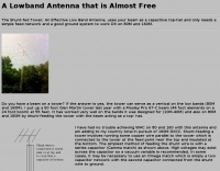 The Shunt-fed Tower, an effective Low Band Antenna, uses your beam as a capacitive top-hat and only needs a simple feed network and a good ground system to work DX on 80M and 160M.
 -
 Presents the KE4UYP linear-loaded vertical antenna design, which introduces very little loss on 80 or 160 meters, achieving an overall radiation efficiency of 80% to 85%. This design addresses common pitfalls of traditional base-fed verticals by placing the majority of the current at the top of the antenna, eliminating the heavy reliance on extensive ground radial systems. The author's initial 10-meter model, only three feet tall, yielded 5/9 signal reports to Anchorage, AK, and Europe, confirming its effectiveness. The antenna incorporates both vertically and horizontally polarized radiators, with a 1/4 wavelength horizontal counterpoise located at the feed-point, near the top, to create an almost totally omnidirectional pattern with high wave angle horizontally polarized radiation. This dual polarization ensures even illumination across all take-off angles, making it effective for both local contacts and **DXing**. The vertical element is linear loaded, adding capacitance reactance and making it longer than the horizontal element to achieve resonance and raise the feed-point impedance to 50 ohms. Fine-tuning the antenna requires careful adjustment, as tower reactance can vary. The article suggests starting with 80 feet for 80m and 170 feet for 160m for the vertical wire, then trimming for resonance. Bandwidth specifications include 300 kHz under 2:1 **SWR** on 80m and 100 kHz on 160m when suspended between trees, or 150 kHz on 80m when side-mounted on a tower.
 -
 The page provides detailed information about the construction of a full-size 160M 3 element beam antenna and an 80M 5 element beam antenna on a 330ft tower. It includes specifics about the tower height, types of antennas, elements, gain, take off angles, front-to-back ratio, operating frequencies, weight, and dimensions of the beams. The content is aimed at amateur radio operators interested in building high-performance antennas for the 160M and 80M bands. This Antenna is now been destroyed and is no more operational.
 -
 JJ0DRC's HF multi-band delta loop antenna project, initially conceived during the waning peak of Cycle 23, addresses the common challenge of achieving effective DX operation from a small residential lot in Japan. Dissatisfied with a ground plane antenna's performance in SSB pile-ups, the author sought a beam-like solution without a tower, drawing inspiration from a JJ1VKL article in CQ Ham Radio Sep. 2000. The antenna, constructed in October 2000, employs two 7.2-meter fishing rods (37% carbon fiber, reinforced with cyano-acrylate glue and aluminum tape) and 1mm enameled wire, fed by an Icom AH-4 external antenna tuner. While the exact beam pattern remains unmeasured, JJ0DRC observed a significantly higher callback rate compared to dipole antennas, particularly on higher bands. The system's circumference length of 15-20m is crucial for maintaining a good beam pattern across HF bands, though performance on lower bands like 80m, 40m, and 30m becomes less directional as the length deviates from a full wavelength. Ongoing maintenance addressed degradation issues, including aluminum tape cracking and wire breakage at connection points due to strong winds (often exceeding 10-15m/s in winter). The author reinforced rod connections with IRECTOR PIPE SYSTEM components and INSU-ROCK ties, and improved wire attachment methods using Cremona rope and epoxy bond to enhance durability.
 -
 Deploying robust antenna infrastructure for both fixed and portable operations often requires specialized support structures capable of withstanding environmental stresses while providing optimal radiating element placement. SMC offers a range of solutions, including pneumatic masts and push-up masts, designed to facilitate rapid deployment and reliable long-term support for various antenna types. Their product line encompasses antenna mounts, poles, and complete antenna systems, addressing the critical need for stable and efficient RF communication. The company's offerings extend to HF antennas, including dipoles and _NVIS_ (Near Vertical Incidence Skywave) antennas, which are crucial for short-range regional communications on bands like 80m and 40m. These systems are engineered for durability and performance, ensuring signal integrity across diverse operating conditions. With over **65 years** of experience, SMC has established itself as a global manufacturer in this niche. Their product portfolio also includes antenna support towers, catering to more permanent installations requiring significant height and load capacity for multiple arrays.
 -
 This project details the construction of a **full-sized 40-meter vertical antenna**, born from a renewed interest in 7 MHz operation and a desire for improved effectiveness over simple dipoles. The author, K5DKZ, initially focused on VHF experimentation, which provided an inventory of aluminum tubing and fiberglass spreaders for this endeavor. Before this vertical, K5DKZ utilized an 80/40 meter inverted-vee trap dipole and a 40-meter broadband dipole, but now primarily uses a pair of full-sized, phased, quarter-wave verticals spaced 35 feet apart for serious 40-meter work. The construction involves a base-heavy design for stability, using a 44.5-inch section of 1-1/4 inch steel TV mast driven into 1-3/8 inch aluminum tubing, insulated by a 105-inch section of Schedule 40 PVC pipe. The assembly reaches 31 feet, close to the 32 feet required for a quarter-wavelength on 40 meters, with fine-tuning achieved by winding wire onto a fiberglass spreader. The design is explicitly presented as a foundation for a two-element 40-meter Yagi beam, outlining modifications like substituting aluminum for steel in the base and using an inductive hairpin match for the driven element. The article also discusses tuning considerations for a large 40-meter beam, noting the 100 to 200 kHz upward frequency shift when raised, and suggesting methods for installation on a tower. The author emphasizes the cost-effectiveness and good performance of the monopole approach, especially when multiple verticals are needed.
 -
 A 38-foot Tristao Tower, similar to the U.S. Tower HDX538, was installed twice by the author, first in 1980 and then reinstalled in 1989. The resource details the challenges of self-performing heavy construction tasks like breaking concrete and digging a 3' x 3' x 6' deep footing, contrasting it with hiring professionals for the second installation. It highlights the financial and physical costs associated with DIY tower foundation work, noting a rebar cage cost of $65 in 1980 versus $150-$175 today, and the expense of tools for bending rebar. The content emphasizes the critical importance of obtaining building permits, recounting how a permit in Buena Park, California, nullified a neighbor's complaint about TVI. It also discusses the necessity of adhering to local building codes, such as the 1975 UBC and the subsequent 1985 UBC recertification requirement, which reduced the allowed antenna wind loading from 30 square feet to 20 square feet for the author's _KT34A_ Yagi. The footing depth also increased from 6 feet to 6.5 feet under the newer code. Practical advice includes hiring licensed contractors for specialized work, delaying antenna installation for a month after raising the tower, and verifying buried utilities before any excavation. The author provides specific examples of utility location services like _DigAlert_ in California, underscoring the legal and safety implications of neglecting this step. The narrative is grounded in personal experience, offering a realistic perspective on tower projects.
 -
 How to improve your transmitting antennas for very low solar activity periods, vertically polarized 160 meter antennas, horizontally polarized 80 to 10 meter antennas, single or stacked yagis, multi-tower stations
 -
 Documents the operational experiences and technical insights of amateur radio station VA3STL, offering a firsthand account of various on-air activities and equipment. The blog features a detailed narrative of a **QRP transatlantic QSO** on 12m SSB, achieving a 55 report with 10W to a mobile station in Italy using a homebrew 90ft doublet antenna. It also introduces the _Ten-Tec 539_ QRP HF transceiver, a 10W output rig covering 80m through 10m, designed for portable operations and featuring DSP and dual VFOs. The resource also delves into historical radio technology, specifically the "Gibson Girl" survival radio, an emergency transmitter operating on 500kHz (and later 8280/8364 kHz) with a hand-cranked generator and kite-deployed antenna. This section explores its origins from German designs and its use during World War II, including its distinctive curved shape for ergonomic hand-cranking. Further historical content includes a visit to Signal Hill in St. John's, Newfoundland, commemorating Marconi's reception of the first transatlantic radio signal in 1901. The post describes the Cabot Tower exhibit and the VO1AA station, highlighting the site's significance despite the thick fog during the visit. It also showcases a homebrewed _Marconi-style straight key_ by WB9LPU, crafted to celebrate the centenary of Marconi's achievement.
 -
 Operating in a Single Operator Two Radios (SO2R) setup, especially with beverage antennas, often exposes the receiving radio's front-end to significant RF energy from the transmitting radio. This resource details a practical, homebrew receiver protection circuit designed to mitigate this risk. The core of the design involves a non-inductive 2W 22 Ohm carbon composition resistor in series with the RX antenna line, followed by two stacks of four fast-switching diodes (e.g., _1N914_) configured in opposite polarizations. This arrangement effectively clamps the incoming voltage to approximately 2.8 V peak-to-peak, safeguarding sensitive receiver input components. The series resistor plays a crucial role by absorbing excess power, preventing the diodes from exceeding their current ratings and potentially failing open, which would leave the receiver unprotected. The author, _N4KG_, measured up to 50 watts of coupled power between 80M slopers on the same tower, highlighting the necessity of such protection. The design is presented as a cost-effective solution to prevent damage to receiver input transformers, with the author noting successful protection of a receiver even after a resistor showed signs of overheating. This simple circuit can be integrated via a transverter plug, offering a robust defense against high RF input.
 -
 Building an 80-160 meter antenna in a small garden (9m x 14m) involves creative solutions due to space constraints. This project outlines the construction of a trapped 80-160 meter vertical dipole, utilizing a crank-up tower and an 11-meter fiberglass pole. The design prioritizes minimal visibility, ease of construction, and cost-effectiveness, achieving effective operation despite limited space.
 -
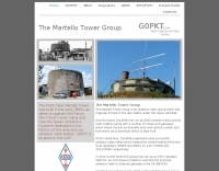 The Martello Tower Group is an amateur radio group which was originally formed in the late 1980s under the name ClackPak.
 -
 WB8LZR details the construction and initial field results of a multi-band vertical wire antenna, designed to complement his existing horizontal loop for improved DX on 80 meters. The antenna utilizes a 67-foot vertical wire, configured as a quarter-wave radiator on 80m, and employs a 1:1 current balun for RF isolation on 80m, 30m, and 17m. For bands like 40m, 20m, and 10m, where the wire acts as a half-wave or full-wave radiator, an additional impedance transforming _unun_ is integrated to manage the significantly higher feedpoint impedance and voltage. The author notes the vertical's performance as a receiving antenna, observing reduced noise compared to his main horizontal loop, particularly on 80m, and even hearing some long-path signals the loop missed. Initial QRP contacts, including a **1-watt** QSO with a _VP2 station_ on 30m, demonstrate its transmit capability. While the radial system is currently rudimentary, the project outlines practical considerations for multi-band vertical deployment and impedance matching.
 -
 This article demonstrates how to convert an existing tower into a dual-band vertical antenna for 80- and 160-meter DX operation. Using EZNEC modeling and practical design principles, the authors achieved a low-profile, efficient setup with a single coax feed line, no moving parts, and optimal radiation patterns. The system integrates an 80-meter vertical wire and a 160-meter shunt-fed gamma match for simultaneous operation. Detailed construction insights, including feed system and capacitor configurations, offer a reliable, full-legal-power solution.
 -
 This paper presents an 80 meter wire 3-element beam antenna in an inverted-V configuration, designed for limited-height towers. Using EZNEC modeling, the antenna features a central parasitic reflector and two switchable driven elements at each end, enabling NE/SW coverage without moving parts or networks. Element lengths are optimized for SSB (3.8 MHz) and CW (3.5 MHz) operation, with a 50 Ω feed and rope-supported boom. The design delivers high gain, effective takeoff angles, and excellent reception, confirmed in real-world DX contest operation. Its simplicity, reliability, and ease of construction make it ideal for operators seeking performance without complex matching systems.