Search results
Query: 80 meter beacon
Links: 8 | Categories: 0
-
 A vertical antenna specifically designed to work with the 80 meter CW beacon keyer
 -
 Demonstrates the operational status and reception reports for the SK6RUD/SA6RR QRPP beacons, which transmit on 478.9 kHz, 1995 kHz, 10.131 MHz, and 40.673 MHz. These beacons utilize extremely low power, with the 630-meter beacon operating at approximately 0.1 watt ERP into an L-antenna, showcasing the potential for long-distance contacts under favorable propagation conditions. The site details the specific frequencies and antenna types employed, such as a vertical at 500 kHz and a 1/4 vertical for higher bands. The resource compiles over 10,530 reception reports from amateur radio operators worldwide, logging details such as date, time, band, RST signal report, locator, distance, and receiver setup. Notable long-distance reports include a 500 kHz reception by AA1A-Dave from 5832 km in 2008 and a 10.133 MHz reception by ZL2FT-Jason from 17680 km in 2010, illustrating the global reach of these low-power transmissions. Each log entry provides specific equipment used by the reporting station, including transceivers like the Yaesu FT817, ICOM IC-7300, and various antenna configurations such as coaxial mag loops, inverted Ls, and end-fed wires. The primary objective of the SK6RUD beacons is to challenge conventional notions of power requirements for effective two-way communication, proving that contacts over significant distances are achievable with minimal output. The site also includes a submission form for new reception reports, fostering community engagement and continuous data collection on propagation phenomena across different bands. The detailed logs offer practical insights into real-world propagation characteristics and the efficacy of QRPP operations.
 -
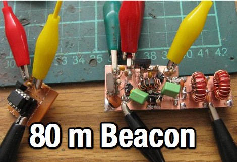 An home made CW beacon transmitter project running 1.5 W on the 80 meters band
 -
 The 2200-meter band (135.7-137.8 kHz) presents unique challenges for amateur radio operators due to its narrow 2.1 kHz bandwidth, low signal levels, and high noise. W1TAG explores various transmission modes suited for this demanding environment, highlighting that traditional voice modes like SSB and AM are impractical. Plain old CW serves as the baseline, demonstrating effectiveness across different modes, though signal-to-noise ratio (SNR) significantly limits practical speeds. The article notes that reducing CW speed below 5 WPM can improve copy, especially with computer-aided spectrum analysis software capable of decoding signals too weak for human ear reception. QRSS, or "CW sent slowly enough that speeds are best expressed in seconds per dot," is a key mode for LF work, with examples ranging from 3 seconds/dot to extreme 240 seconds/dot transmissions. _Argo_ by I2PHD is mentioned as a simple program for QRSS, enabling reception of signals like BRO, a Part 15 beacon, at a distance of **1100 miles**. Other modes discussed include Dual Frequency CW (DFCW), which uses frequency shifts to distinguish dots and dashes, and Binary Phase Shift Keying (BPSK), a phase modulation technique employing 0 to 180-degree phase flips. WOLF (Weak-signal Operation on Low Frequency), a specialized BPSK form by KK7KA, encodes 15-character messages into 960-bit packages, taking 96 seconds to transmit, and has demonstrated successful reception over **672 seconds** for a message from a 1-watt beacon. Further modes include PSK, FSK variations like JASON and MSK, and graphical modes such as Hellschreiber and Chirped Hell. The article concludes with a practical chart comparing the time required to send a simple message like "WD2XES FN42CH " across these diverse LF modes, offering valuable insights for operators planning contacts on the low bands.
 -
 The ZS1J/B beacon operates on 28.2025 MHz with 5 Watts output to a half-wave, end-fed vertical antenna, initially installed in 1977 as ZS5VHF near Durban. The 10-meter transmitter is a modified 23-channel CB radio, and the identification keyer uses a diode matrix unit with TTL ICs from the same era. After relocation to Plettenberg Bay in 1993, the beacon has been in continuous service, with additional QRP transmitters later installed for other bands. In 1994, a single-transistor, 80-meter, 0.5-watt QRP transmitter with a half-wave dipole was added on 3586 kHz, followed by a 160-meter, 0.5-watt unit on 1817 kHz. A 30-meter, 0.5-watt transmitter was installed in 1996, operating on 10.124 MHz. In 2002, a 40-meter QRRP beacon on 7029 kHz, with an output of 100 microwatts, achieved DX reports up to 1100 km from ZS6UT in Pretoria. Best DX reports for the 80m and 160m beacons came from 9J2BO.
 -
 DF0WD/DL4YHF's Longwave Overview details amateur radio operations on the 135.7 to 137.8 kHz segment in Germany. The author outlines the "inofficial" European band plan, specifying segments for QRSS, TX tests, beacons, conventional CW, and data modes. Early LF activities at DF0WD began with a 20-watt CW transmitter, later upgraded to a homemade linear transverter capable of 100 watts, driven by an Icom IC706 on 10.137 MHz. The station's antenna system includes a 200-meter wire, approximately 10 meters above ground, supported by football field light-masts. Despite its length, the antenna's efficiency is noted as very low due to the immense wavelength of about 2.2 km. The author's experience highlights the significant challenge of achieving effective radiated power (EIRP) on LF, estimating DF0WD's EIRP at around 80 milliwatts based on field strength measurements from PA0SE. DF0WD/DL4YHF has successfully worked numerous countries on 136 kHz CW, including DL, F, G, GI, GM, GU, GW, HB9, HB0, LX, OE, OH, OK, OM, ON, OZ, PA, and SM. The author also mentions ongoing efforts to log contacts with CT, EI, LA/LG, and to complete a two-way QSO with Italy, demonstrating persistent activity on this challenging band.
 -
 This article introduces an Arduino-based QRP CW Transceiver designed for lower HF bands. The journey begins with the Wotduino, evolving from a keyer to a multi-mode beacon. The development includes a QRP transmitter and culminates in a receiver inspired by Roy Lewallen design. The transceiver, controlled through a control bus features a signal path, modulation, filtering, and adjustable frequency settings. Despite initial testing intentions, successful QSOs on 80 and 40 meters showcase its functional capabilities.
 -
 This blog chronicles the development of an 80-meter vertical antenna for amateur radio operation. The author constructs a top-loaded vertical using fiberglass poles, achieving significant performance improvements over their previous end-fed wire antenna. Comparative testing using the Reverse Beacon Network and on-air contacts demonstrates 8-10 dB gain on the east coast. The project evolved to include 40-meter capability through a modified design featuring a four-wire vertical cage, loading coil, and strategic guying system. Despite challenges with signal wobble during windy conditions, the vertical consistently outperforms the end-fed wire, particularly for reaching distant stations during nighttime propagation.