Search results
Query: 80 meter end fed antenna
Links: 22 | Categories: 0
-
 This PDF article from April 2001 QST details the construction of the "NJQRP Squirt," a reduced-size 80-meter inverted-V dipole antenna. The resource provides a general construction sketch, a photograph of the assembled antenna, and specific dimensions for PC-board insulators. The antenna consists of two wire legs, each approximately **34 feet long**, separated by 90 degrees, fed at the center. It is designed for operation on 80 meters (3.5-4.0 MHz) as a quarter-wavelength antenna, requiring a low-loss feedline and an external antenna tuner due to its non-resonant feedpoint impedance. Construction utilizes readily available materials, including 1/16-inch glass-epoxy PC board for end and center insulators, and #20 or #22 insulated hookup wire for the elements. The feedline specified is 300-ohm TV flat ribbon line, with a note on potential trimming for tuner compatibility. N2CX reports the antenna's center should be elevated to at least **20 feet**, with ends no lower than seven feet above ground, resulting in a ground footprint of approximately 50 feet wide. The design prioritizes NVIS propagation for local 80-meter contacts. DXZone Focus: PDF Article | 80m Inverted-V Dipole | Construction Notes | 34 ft element length
 -
 Presents the KE4UYP linear-loaded vertical antenna design, which introduces very little loss on 80 or 160 meters, achieving an overall radiation efficiency of 80% to 85%. This design addresses common pitfalls of traditional base-fed verticals by placing the majority of the current at the top of the antenna, eliminating the heavy reliance on extensive ground radial systems. The author's initial 10-meter model, only three feet tall, yielded 5/9 signal reports to Anchorage, AK, and Europe, confirming its effectiveness. The antenna incorporates both vertically and horizontally polarized radiators, with a 1/4 wavelength horizontal counterpoise located at the feed-point, near the top, to create an almost totally omnidirectional pattern with high wave angle horizontally polarized radiation. This dual polarization ensures even illumination across all take-off angles, making it effective for both local contacts and **DXing**. The vertical element is linear loaded, adding capacitance reactance and making it longer than the horizontal element to achieve resonance and raise the feed-point impedance to 50 ohms. Fine-tuning the antenna requires careful adjustment, as tower reactance can vary. The article suggests starting with 80 feet for 80m and 170 feet for 160m for the vertical wire, then trimming for resonance. Bandwidth specifications include 300 kHz under 2:1 **SWR** on 80m and 100 kHz on 160m when suspended between trees, or 150 kHz on 80m when side-mounted on a tower.
 -
 This PDF File desscribes how to homemade a multi-band end-fed trapped wire antenna resonating on the low bands of 160 80 and 40 meters. Contains trap design instructions and some construction tips.
 -

-
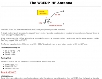 G3YCC article pn the W3EDP end-fed antenna for 80 to 20 meters bands
 -
 An 85ft wire fed against a 17ft counterpoise that works well in 80 and 40 meters
 -
 The G5RV multiband HF antenna, designed by Louis Varney (G5RV) in 1946, is a popular compromise antenna offering good overall performance on most HF bands when paired with an external antenna tuner. The basic full-size G5RV measures 102 feet across the top for 80 through 10 meter operation and is fed at the center via a 34-foot low-loss feed-stub. This interaction between the radiating section and the feed-stub facilitates matching across 80-10 meters with a standard tuner, often eliminating the need for ladder line directly to the shack. The antenna's design center frequency is 14.150 MHz, configured as a 3/2-wave dipole on 20 meters, with its 102-foot length derived from long-wire antenna formulas. Construction details emphasize the matching section, which can be open wire, ladder line (window-type), or TV twin lead. Each type has a specific velocity factor (VF) affecting its physical length for an electrical half-wave on 14 MHz; for instance, open wire requires 33.7 feet (VF 0.97), ladder line 31.3 feet (VF 0.90), and TV twin lead 28.5 feet (VF 0.82). The article provides formulas for calculating these lengths and discusses the antenna's behavior on individual bands, from 3.5 MHz where it acts as a shortened dipole, to 28 MHz where it functions as two three-half-wave long-wire antennas fed in-phase. Practical construction notes include recommendations for vertical descent of the matching section, sealing the coax junction, providing strain relief, and winding a coaxial choke coil to mitigate common mode current. The resource also presents dimensions for double-size (204 ft) and half-size (51 ft) G5RV versions, along with their corresponding matching section lengths for various line types, making it a versatile reference for hams considering this classic wire antenna.
 -
 The X80 multi-band HF vertical antenna, a commercial iteration of the Rybakov design, exhibits a physical length of 5.5 meters, or approximately 18 feet, and is constructed from aluminum tubing. It operates as a non-resonant vertical, requiring an external antenna tuner for impedance matching across its intended operating frequencies. The antenna's design incorporates a 1:4 UNUN at its base, facilitating a nominal 50-ohm feed point impedance for the coaxial cable. Performance observations indicate effective operation on 40 meters, 20 meters, 15 meters, and 10 meters, with reduced efficiency on 80 meters and 160 meters due to its relatively short electrical length for these lower bands. Comparative analysis with a G5RV dipole and a half-wave end-fed antenna reveals the X80 offers a lower take-off angle, beneficial for DX contacts, particularly on the higher HF bands. Field tests conducted with an Icom IC-706MKIIG transceiver and an LDG AT-100ProII autotuner demonstrate the X80's ability to achieve acceptable SWR across 80m through 10m. The antenna's compact footprint and ease of deployment make it suitable for restricted spaces or portable operations, though its performance on 80 meters is noted as a compromise compared to full-size resonant antennas.
 -
 Demonstrates the operational status and reception reports for the SK6RUD/SA6RR QRPP beacons, which transmit on 478.9 kHz, 1995 kHz, 10.131 MHz, and 40.673 MHz. These beacons utilize extremely low power, with the 630-meter beacon operating at approximately 0.1 watt ERP into an L-antenna, showcasing the potential for long-distance contacts under favorable propagation conditions. The site details the specific frequencies and antenna types employed, such as a vertical at 500 kHz and a 1/4 vertical for higher bands. The resource compiles over 10,530 reception reports from amateur radio operators worldwide, logging details such as date, time, band, RST signal report, locator, distance, and receiver setup. Notable long-distance reports include a 500 kHz reception by AA1A-Dave from 5832 km in 2008 and a 10.133 MHz reception by ZL2FT-Jason from 17680 km in 2010, illustrating the global reach of these low-power transmissions. Each log entry provides specific equipment used by the reporting station, including transceivers like the Yaesu FT817, ICOM IC-7300, and various antenna configurations such as coaxial mag loops, inverted Ls, and end-fed wires. The primary objective of the SK6RUD beacons is to challenge conventional notions of power requirements for effective two-way communication, proving that contacts over significant distances are achievable with minimal output. The site also includes a submission form for new reception reports, fostering community engagement and continuous data collection on propagation phenomena across different bands. The detailed logs offer practical insights into real-world propagation characteristics and the efficacy of QRPP operations.
 -
 In this experiment the autor is going to explore the use of a 1:64 matching network on the End Fed Long Wire Antenna. Experiment will consist in build a 80-40-20-15-10 meter End Fed Long Wire Antenna with a 1:64 matching network from the documentation available on the internet
 -
 A wire antenna feeded with an unsymmetrical feed and a 1:4 balun can be tuned from 6 to 80 meters band but can be noisier than a dipole and cause RF in the shack
 -
 The NB6Zep Antenna, an electrically shortened 80-meter end-fed wire, addresses space constraints for low-band operation by integrating two loading coils into a 37-foot wire. This design, modeled with _EZNEC_, explores configurations like the quarter-wave sloper and inverted-L, with the latter providing a more vertical radiation pattern and practical backyard deployment. The resource details specific coil construction, recommending 21 uH coils made from _BW coil stock #3026_ or similar, and outlines wire segment lengths for optimal tuning. Performance analysis indicates a radiating efficiency of approximately 27% with good ground conductivity, resulting in a signal typically 3-4 dB down compared to a full-size quarter-wave vertical. The antenna exhibits a narrow bandwidth, around 50 kHz, due to its high Q, necessitating a tuner for broader band operation. Feedpoint impedance is low, with ground resistance playing a critical role in achieving a usable SWR. The article emphasizes the importance of an effective ground rod at the feedpoint for proper operation and tuning, suggesting an antenna analyzer for precise adjustments. It confirms the antenna's suitability for DX, citing successful contacts from Oregon to the East Coast and Hawaii on a 160-meter variant, making it a viable option for urban operators seeking low-angle radiation on 80 meters.
 -
 A multi band antenna for HF band capable to operate from 10 to 80 meters band depending on wire lenght loaded with a small inductance neat the feed end.
 -
 The ZS1J/B beacon operates on 28.2025 MHz with 5 Watts output to a half-wave, end-fed vertical antenna, initially installed in 1977 as ZS5VHF near Durban. The 10-meter transmitter is a modified 23-channel CB radio, and the identification keyer uses a diode matrix unit with TTL ICs from the same era. After relocation to Plettenberg Bay in 1993, the beacon has been in continuous service, with additional QRP transmitters later installed for other bands. In 1994, a single-transistor, 80-meter, 0.5-watt QRP transmitter with a half-wave dipole was added on 3586 kHz, followed by a 160-meter, 0.5-watt unit on 1817 kHz. A 30-meter, 0.5-watt transmitter was installed in 1996, operating on 10.124 MHz. In 2002, a 40-meter QRRP beacon on 7029 kHz, with an output of 100 microwatts, achieved DX reports up to 1100 km from ZS6UT in Pretoria. Best DX reports for the 80m and 160m beacons came from 9J2BO.
 -
 An interesting article on end fed half-wave wire antennas with a couple of original experiments. Author illustrate the role of the QRP matchbox, and a 40/20 meter antenna with a center stub making it a large bandwidth antenna for 40 and 20. Includes also an 80/40 end fed with the typical coil to make it available on 80 merts band.
 -
 This type of antenna is a popular antenna design as the performance is very good across the HF bands and requires little or no tuning. It’s a dipole fed off center with a 4:1 balun at the offset feed point. The antenna shown covers 80, 40, 20 and 10 meters. The formula can also be used to adjust the overall length to cover more or fewer bands and the resulting overall length. 160-10m, 80-10m or 40-10 meters depending on your available space. Other bands will require a tuner.
 -
 With this antenna the coverage is 80,40,20,15 and 10 meter band without any antenna tuner and the average SWR is below 1.2 on phone bands. The total antenna lenght is about 23 meters , with one 20.4 meters long segment from the 1:49 transformer to the 110uh coil and about 2.2 meters long segment from the coil to the insulator.
 -
 Vertical end fed antenna used for portable operations. The antenna will work on 80 with acceptable results, it will work fine on 40m, and it will be a good deal better than a normal 1/4 wave GP on 20, 17, 15 meters.
 -
 Experimentin wire antennas on top band using several type of aerials. This includes a 40 to 160 meters EndFed Half Wave kite antennas and 160m/80m loaded vertical antenna.
 -
 The 80-meter Skyloop antenna, a top-performing HF antenna, excels in weak signal work, low-noise operation, and omnidirectional coverage. Ideal for fixed stations, it delivers strong performance at low power, outperforming many alternatives, including 80m half-wave end-fed antennas. Requiring significant space for deployment, it’s well-suited for NVIS and groundwave use. Though not portable, it’s cost-effective and durable, with minor maintenance needs. Tuning may require adjustments for optimal resonance. It’s a standout for base stations, though a lighter portable version could enhance its versatility.
 -
 This blog chronicles the development of an 80-meter vertical antenna for amateur radio operation. The author constructs a top-loaded vertical using fiberglass poles, achieving significant performance improvements over their previous end-fed wire antenna. Comparative testing using the Reverse Beacon Network and on-air contacts demonstrates 8-10 dB gain on the east coast. The project evolved to include 40-meter capability through a modified design featuring a four-wire vertical cage, loading coil, and strategic guying system. Despite challenges with signal wobble during windy conditions, the vertical consistently outperforms the end-fed wire, particularly for reaching distant stations during nighttime propagation.
 -
 This page provides guidance on designing an End-Fed Half-Wave (EFHW) or Random-Length antenna for amateur HF bands, such as 80 or 40 meters. The content explains how to optimize the antenna for multi-band use and match it to a 50-ohm system using an unun. Hams can generate radiation patterns, VSWR charts, and antenna current diagrams for their customized antenna designs. Understanding how antenna dimensions affect performance is essential for successful field operations. The page caters to ham radio operators looking to build efficient and effective HF antennas for their stations.