Search results
Query: amplitude modulation
Links: 11 | Categories: 1
Categories
-
 Eight-channel Audio Spectrum Analyzer is a set of Real-Time Multi-Channel Gauges for investigation of data accepted from any ADC you will want or 16-, 24- and 32-bit ADC of sound card. WDM drivers support. FFT Spectrum Analysis, OscilloScope, Frequency counter, AC/DC voltmeter, Signal-to-Noise Ratio, Signal-to-Noise and Distortion, Spurious-Free Dynamic Range, Effective Number Of Bits, Total Harmonic Distortion, Inter-Modulation Distortion, Phase Shift. Special modes of dual-channel FFT spectral analysis: Separate channels spectra, Spectra of digital sum, difference, product of two signals, Spectrum of digital product of original signal and its fundamental, Spectrum of Real and Complex Transfer Function, Cross Spectrum. Standart weighing of spectra according IEC and CCIR. Oscilloscope modes (for dual-channel ADC) are: original signals, sum, difference, dependence of one channel on another, amplitude distribution of input signals.
 -
 Presents a QRP AM/CW transmitter project specifically designed for the 10-meter band, utilizing a crystal oscillator and a collector-modulated AM oscillator. The design employs a 2N2219(A) transistor in a Colpitts configuration, generating 100 to 350 mW of RF output power depending on the 9-18 Volt supply voltage and modulation depth. Frequency stability is maintained by a 28 MHz crystal, with fine-tuning possible via a Ct1 trimmer capacitor for approximately 1 kHz adjustment. The resource details the RF oscillator stage, implemented with a 2N2219 NPN transistor, emphasizing frequency stability and low power dissipation. It also covers the amplitude modulation stage, managed by a 2N2905 PNP transistor, which impresses audio information onto the carrier. Selective components (C3, C4, C7, C5) enhance voice frequencies within a +/- 5 kHz bandwidth, and modulation depth is controlled by R2 and R3. The project includes a 3-element L-type narrow bandpass filter (Ct3, L3, C10) to suppress harmonics and ensure a clean output signal. The project provides a complete schematic diagram, a comprehensive parts list including specific capacitor, resistor, and inductor values, and construction notes for the coils (L1, L2, L3). It also offers practical advice on enclosure requirements, suggesting an all-metal case or a PVC box with graphite paint for RF shielding. Operational parameters such as current draw (27mA@9V to 45mA@16V) and input impedance (50 Ohms) are specified, alongside guidance on antenna matching and the importance of a valid amateur radio license for 10-meter band operation.
 -
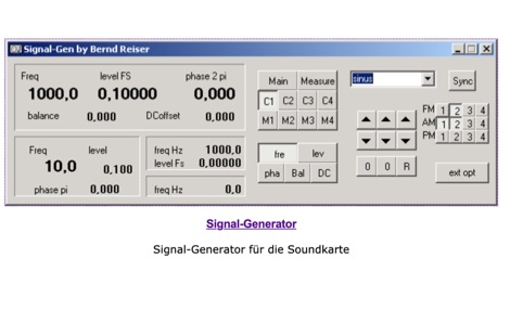 Windows signal function generator sotfware, offers 4 main channels, 4 modulators, 1 measurement generator, 1 frequency standard generator, Amplitude, phase and frequency modulation, can generates real band-limited signals
 -
-
 Amplitude Modulation Forever for ham radio operators, shortwave listeners and collectors
 -
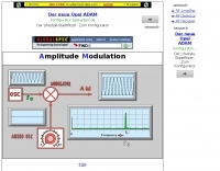
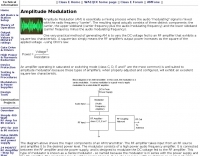 Amplitude Modulation (AM) is essentially a mixing process where the audio modulating signal is mixed with the radio frequency carrier
 -
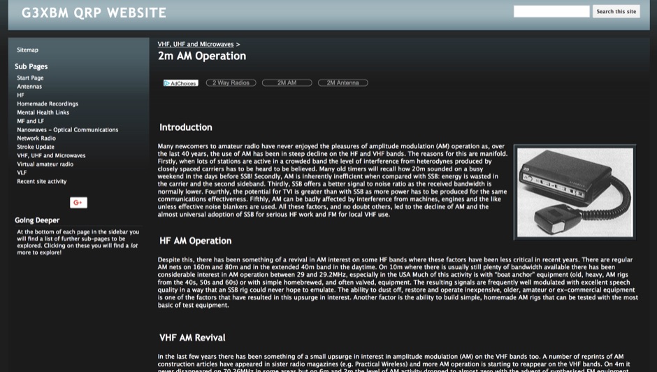 An article on amplitude modulation (AM) operation on VHF bands.
 -
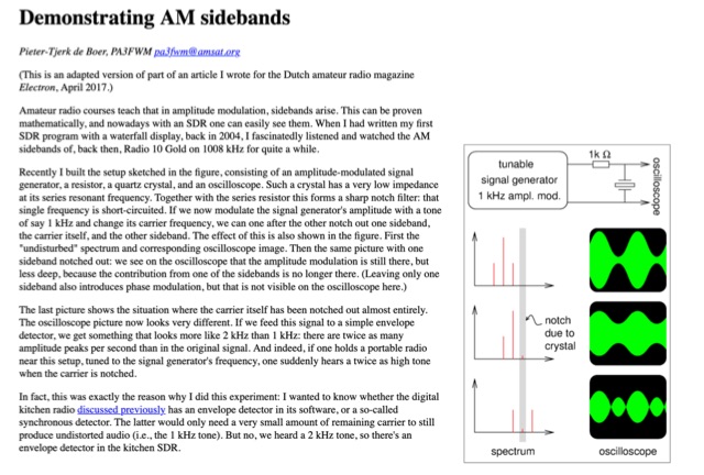 Amateur radio courses teach that in amplitude modulation, sidebands arise. This can be proven mathematically, and nowadays with an SDR one can easily see them.
 -
 The Olivia digital mode, a **Multi-Frequency Shift Keying (MFSK)** radioteletype protocol, is specifically engineered for robust communication under difficult propagation conditions on shortwave radio bands from 3 MHz to 30 MHz. Developed by Pawel Jalocha in 2003, Olivia signals can be decoded even when the noise amplitude exceeds the digital signal by over ten times, making it highly effective for transmitting ASCII characters across noisy channels with significant fading and propagation phasing. Early on-the-air tests by Fred OH/DK4ZC and Les VK2DSG on the Europe-Australia 20-meter path demonstrated intercontinental contacts with as little as one-watt RF power under favorable conditions. Common Olivia modes are designated as X/Y, where X represents the number of tones and Y is the bandwidth in Hertz, with examples including 8/250, 16/500, and 32/1000. The resource clarifies that Olivia, unlike some other digital modes, produces a constant envelope, allowing RF power amplifiers to achieve greater conversion efficiencies and making it less prone to non-linearity. Operators are advised that **Automatic Level Control (ALC)** can be set higher than no meter movement for MFSK modulation, as long as it's not driven past its high limit, contrary to common misinformation about other digital modes. The Olivia community encourages voluntary channelization on suggested calling frequencies, such as 14.0725 MHz for 8/250, to facilitate initial contacts, especially for signals below the noise floor. The Olivia Digital DXers Club provides links to Groups.io, Facebook, and Discord for community engagement and offers details on QSO parties.
 -
 The Florida AM Group operates a weekly Amplitude Modulation (AM) net on 3885 kHz every Sunday morning, with a pre-net starting at 6:30 AM Eastern Time and the formal net at 7:00 AM. This group focuses on the preservation, restoration, and on-air operation of antique Amateur, commercial, homebrew (HB), and Military Radio equipment, emphasizing **Amplitude Modulation** (AM) mode. Participants are encouraged to use AM mode, regardless of whether they possess vintage gear, fostering a community around classic radio operation and the distinctive high-fidelity audio associated with **vacuum tube** equipment. The net utilizes NetLogger software for check-ins and round table management, providing a structured environment for participants. The group regularly publishes net control schedules, listing operators like NZ1Q, K1HH, and W3XM, and organizes various in-person events such as Hamcation gatherings, luncheons, and boat anchor swap meets. These activities facilitate eyeball QSOs and equipment exchanges, reinforcing the community aspect beyond on-air operations. The Florida AM Group also provides contact information for net control volunteers and shares news, including SK (Silent Key) announcements for members like Steve KI4RUS and Roy W4IDD, highlighting the group's long-standing camaraderie and shared passion for AM radio.
 -
 Early 20th-century transatlantic wireless communication efforts involved distinct technical approaches by Reginald Fessenden and Guglielmo Marconi. Marconi's systems, operational until approximately 1912, primarily utilized _spark technology_ for wireless telegraphy, facilitating Morse code communication between ships and across oceans. His Poldhu station in December 1901 radiated signals in the MF band around 850 kHz, later evolving to 272 kHz in October 1902, and eventually 45 kHz by late 1907 with increasingly larger antenna structures like the pyramidal monopole and capacitive top-loaded arrays. Fessenden, conversely, focused on _continuous wave transmission_ for wireless telephony, recognizing its necessity for speech. His transatlantic experiments in 1906 employed synchronous rotary-spark-gap transmitters and 420-foot umbrella top-loaded antennas at Brant Rock, MA, and Machrihanish, Scotland, tuned to approximately 80 kHz. Fessenden later utilized the _Alexanderson HF alternator_ at 75 kHz by late 1906 for pure CW transmission, integrating a carbon microphone for amplitude modulation. Receiver technology also differed, with Marconi initially relying on untuned coherer-type detectors, later developing the magnetic detector in 1902, while Fessenden's CW approach necessitated more advanced detection methods.