Search results
Query: antennas calculation for
Links: 21 | Categories: 0
-
 The Cubical Quad antenna is a popular choice among amateur radio operators due to its robust design and excellent performance characteristics. This resource provides essential scaling formulas that help determine the lengths of the antenna elements and the necessary gamma match values for various frequencies. The design is adaptable, allowing operators to optimize for gain or front-to-back ratio by adjusting the spacing between elements. The accompanying Excel files facilitate precise calculations, making it easier for both beginners and experienced hams to construct their own Cubical Quad antennas. In addition to the design formulas, the resource includes practical insights from the author, who has successfully built and utilized these antennas in various field events. The document outlines the tuning process for achieving minimum VSWR, ensuring optimal performance. With detailed illustrations and performance data, this guide serves as a comprehensive reference for anyone looking to delve into Cubical Quad antenna construction and optimization, enhancing their amateur radio experience.
 -
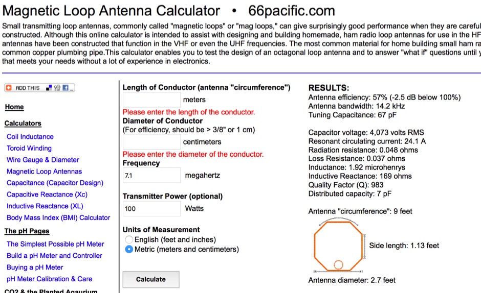 A free online calculator for making all of the calculations required to design and build small transmitting loop antennas, also known as magnetic loops by 66pacific.com
 -
 End-Fed Half-Wave Antennas (EFHWAs) are analyzed for their utility in portable QRP operations, emphasizing their simplicity, efficiency, and predictable radiation patterns compared to other portable antenna types. The discussion contrasts EFHWAs with vertical antennas, random length wires, and center-fed dipoles, highlighting the common pitfalls of each, such as ground system dependency for verticals and feedline issues for dipoles. The article details the electrical half-wavelength calculation using the formula L (Ft) = 468/F(MHz) and explains how EFHWAs can be resonant on harmonic frequencies, enabling multiband operation. Various deployment configurations are presented, including the inverted L, inverted Vee, sloping wire, and vertical setups, each with specific advantages for radiation angle and polarization. For instance, a vertical EFHWA offers a low angle of radiation suitable for DX contacts without requiring an extensive ground system. The resource also addresses the counterpoise requirements, suggesting a quarter-wavelength wire or connection to a metallic structure for decoupling. A schematic diagram for a simple parallel-tuned circuit tuner, based on the _Rainbow Bridge/Tuner_ design, is provided, detailing component values for 30 and 40 meters, including a 6 microhenry toroidal inductor and a 20-100 picofarad mica compression capacitor. The tuner's adjustment process for SWR matching is also outlined.
 -
 G4URH calculations to design your own antennas, ground plane, half wave antennas, Quad Antennas and 5/8 verticals
 -
 Demonstrates the design and construction of a 9-element Yagi antenna for the **70 cm band** (432 MHz), based on the DK7ZB concept. The resource details EZNEC+ calculations for a single antenna, providing gain, sidelobe suppression, and front-to-back ratio figures. It also presents a comprehensive analysis of stacking two such antennas, including optimal stacking distance (1000 mm) and the resulting performance enhancements for the stacked array, such as an increased gain of 17.03 dBi. The article includes detailed drawings, wire file dimensions in millimeters, and azimuth/elevation plots for both single and stacked configurations. Practical construction steps are documented with original photographs, illustrating element mounting, the **28 Ohm matching system** using two quarter-wave 75 Ohm transmission lines, and the critical N-connector wiring. It also covers the iterative process of fine-tuning the driven element length to achieve a return loss of 20 dB, validating the EZNEC+ simulation results with actual measurements.
 -
 Designing and constructing portable wire antennas for HF operations, this resource explores several configurations including the _foldback dipole_ for space-constrained setups and an inductively shortened dual-band dipole for 20m and 40m. It details the calculation of inductance for shortened elements, providing a Visual Basic 6.0 program screenshot that illustrates determining coil parameters like turns and length for a **25.5 uH** inductor. The document emphasizes practical considerations such as adjusting wire lengths for optimal SWR, noting that a dual-band dipole achieved SWR below 2:1 on both 20m and 40m, with careful adjustment bringing it under 1.5:1. Further, the resource describes a half-wave antenna matched with a coaxial stub, a method often referred to as the _Fuchskreis_ in German amateur radio circles, to transform the high feedpoint impedance to 50 Ohms. This monoband solution, for a 20m application, uses a stub length of **2.98m** (0.216 lambda multiplied by coax velocity factor) and a shorted stub of approximately 48cm. The coaxial stub design is highlighted for its resilience to ground proximity, allowing it to be rolled up or laid on the ground with minimal SWR impact, making it highly suitable for portable QRP operations.
 -
 Operating magnetic loop antennas requires careful consideration of RF safety, particularly regarding near-field magnetic field intensity. This resource presents calculations for magnetic field strength (H-field) at various distances from a magnetic loop, emphasizing that the H-field is significantly higher than the E-field in the near-field region due to the inductive nature of the radiating element. It provides specific formulas and examples for determining safe operating distances based on power levels and loop dimensions, crucial for compliance with RF exposure limits. The analysis compares calculated H-field values against FCC and ICNIRP maximum permissible exposure (MPE) limits for controlled and uncontrolled environments. It demonstrates that even at QRP power levels (e.g., 5W), the H-field can exceed MPE limits within a few feet of the antenna, necessitating greater separation distances than often assumed for electric field considerations. The practical application of these calculations helps amateur radio operators configure their stations to ensure personnel safety and regulatory compliance when deploying compact, high-Q magnetic loop antennas.
 -
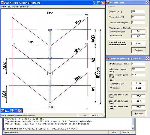 The Triple-M-beam calculation program is used for the calculation of Triple-M-beam antennas by DG0KW
 -
 Mounting antenna close each other. Distance calculations and tips on setting up antennas by KB9VBR
 -
 The calculator designs the Yagi-Uda antenna based on the DL6WU model with boom correction, following the G3SEK-DL6WU method. It optimizes the antenna for maximum gain and allows adjustment of passive elements without affecting SWR. DL6WU antennas are known for their high gain, minimal sensitivity to nearby objects, and stable performance in various weather conditions.
 -
 This is a standard calculation method that can help you while tuning dipole antennas, by adjusting wire lengths. This method can be used also when you need to add lenght to your wires, and can be additionally used to quarter waves vertical antennas
 -
 Coax Velocity Factor in Baluns, Does it Matter? Test results show coaxial cable velocity factor does not always enter into stub length calculations especially in the world of Baluns
 -
 This article shares the author's experience with building antennas. After putting a large magnetic loop project on hold, they decided to try a base-loaded vertical antenna. The author explains how they chose to design a new antenna from scratch, aiming for a frequency of 7 MHz. They describe the calculations needed to find the right coil inductance and how they used 3D-printed parts for the construction. The article wraps up with results from their initial tests, showing good communication on different bands and highlighting the success of their design.
 -
 The HB9CV antenna calculator aids amateur radio enthusiasts in designing antennas for VHF and UHF bands. By inputting the working frequency, users can obtain crucial dimensions like dipole lengths and distances. The tool, based on the HFSS antenna model, provides data on impedance, VSWR, and gain, optimizing front/back radiation ratios. It includes tips for fine-tuning using a Г-matching balun and compensating capacitor, ensuring effective performance and minimal VSWR for enhanced radio communications and direction finding.
 -
 This DIY guide details constructing a 5-element Yagi antenna for VHF frequencies. Yagi antennas offer directional signal transmission/reception compared to omnidirectional ones. The guide covers material selection (aluminum, screws, etc.), design using software or formulas, and step-by-step assembly including cutting elements, drilling holes, and attaching the coaxial cable. While calculations are provided for a 146 MHz design, adjustments are necessary for different frequencies. Safety precautions and potential result variations are emphasized.
 -
 A 5/8 λ antenna, often thought to be ideal for all frequencies, has unique characteristics that don't universally apply. First introduced for medium-wave radio, it works optimally at 225° antenna length over ideal ground, yielding high efficiency. However, at VHF and higher frequencies, it offers no advantage over other antennas due to real ground conditions and complex matching requirements. DIY calculators provide only rough estimates, useful as a starting point for simulations, not for precise builds.
 -
 This article focus on the radiation angle of vertical antennas and the fundamentals of electromagnetic wave propagation. The calculation of antenna length at 145 MHz is followed by an explanation of electromagnetic wave speed and the link between wavelength, frequency, and velocity. Author discusses the 5/8th wave vertical antenna, namely its performance and the influence of radiation angle on signal transmission. Figures and analogies demonstrate how different antenna types produce distinct radiation patterns. This highlights the importance of selecting the right antenna for a certain purpose, such as local traffic or dxing. The article discusses a variety of factors that affect antenna performance, including SWR, propagation conditions, and equipment dependability
 -
 Delta loop antennas, particularly the 30 meter variant, offer unique advantages in terms of vertical polarization and omni-directional coverage. The construction process detailed by VE3VN highlights common mechanical and electrical challenges faced by amateur radio operators. Key design considerations include minimizing interaction with existing contest band antennas, achieving low elevation angles for DX chasing, and ensuring the antenna remains off the ground for agricultural clearance. The article provides specific measurements, such as the loop's height and feed point impedance, which are critical for optimizing performance. The use of NEC modeling software illustrates the importance of accurate resonance calculations, revealing how proximity to the tower affects both pattern and impedance. This practical account serves as a resource for hams looking to build effective antennas while navigating typical construction hurdles.
 -
 This article explores the powerful features of AutoEZ as an Excel application working with EZNEC antenna modeling software. The article demonstrates how variables, equations, and formulas enable versatile antenna design and automatic optimization. Through practical examples including dipoles, inverted vees, delta loops, and monopoles, the author shows techniques for achieving resonance, implementing transmission line resonators for broadbanding, and optimizing antennas across frequency ranges. The step-by-step demonstrations cover unit conversion, coordinate calculations, segmentation considerations, and SWR optimization. This practical guide illustrates how AutoEZ extends EZNEC's capabilities, making complex antenna modeling more efficient and accessible.
 -
 The Beam project offers various features for controlling antenna rotators, including support for 2 or 4 line LCD displays, software or hardware clocks, open collector drives for azimuth and elevation control, and internal calculations for tracking the sun and moon. It can also track satellites and supports "Flip Mode" for inverted antennas. The 4-line version provides detailed readouts while the 2-line version offers a more compact display. New versions now support PWM and I2C H-bridge modes for adjustable speed control at the end of a move.
 -
 This page provides a detailed example of the modeling and analysis of an 80m delta dipole antenna with a 600-ohm bifilar feedline. The model is based on antennas used by the RAF from 1940 to 1970. It covers the original model specifications, conductor mass calculations, resonance frequency observation, geometry adjustment steps, and final antenna dimensions. The content includes theoretical formulas, resonance frequency calculations, and practical steps for adjusting the antenna for optimal performance. Overall, it serves as a practical guide for hams looking to understand and optimize the performance of a delta dipole antenna for the 80m band.