Search results
Query: bread board
Links: 5 | Categories: 0
-
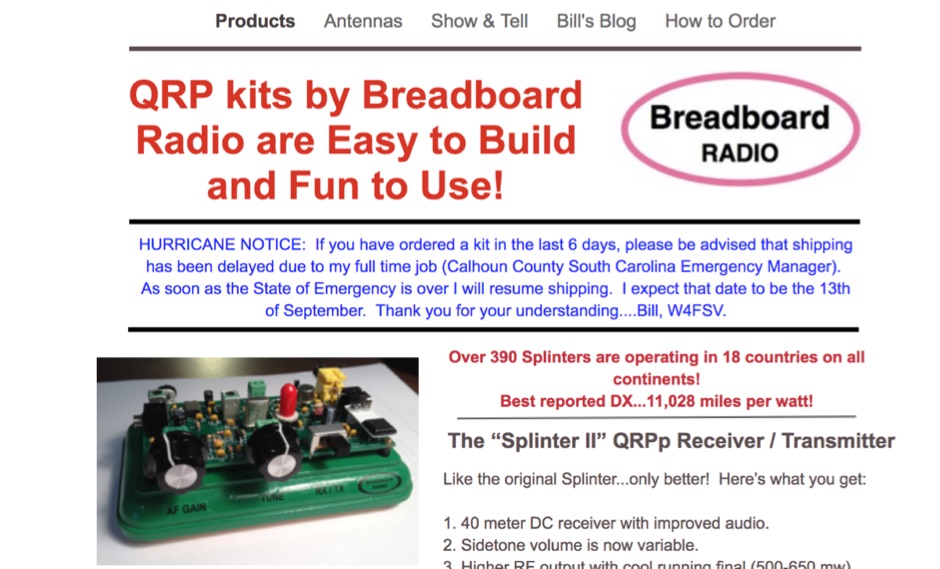 Maker of QRP Kits, QRP CW receiver and transmitters, audio CW Filters, antenna tuners, dummy loads, and morse code practice oscillator
 -
 This article explores the evolution of antenna choices for DXpeditions, focusing on the shift from mono-band VDAs to a multi-band solution. It details the design and construction of a lightweight, versatile 20-17-15m VDA, utilizing readily available materials like fishing rods and IKEA breadboards. The author discusses challenges, adjustments, and offers guidance for replication.
 -
 This project revisits a minimalist software-defined radio (SDR) receiver built using a Raspberry Pi Pico, now optimized for simplicity and affordability. Designed for breadboard assembly with through-hole components, the receiver covers 0–30MHz, supporting CW, SSB, AM, and FM modes with an OLED display and spectrum scope. Key improvements include enhanced frequency accuracy, reduced op-amp saturation, and lower-cost components. Powered by three AAA batteries, it delivers standalone operation for global signal reception. Ideal for hobbyists, the design fosters experimentation and is documented with firmware and schematics available online.
 -
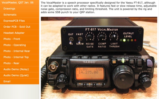 Inspired by Heathkit, author aimed to enhance his Yaesu FT-817 with audio and RF processing. Design goals included a compact enclosure, PCB simplicity, matching jacks, a visual meter, and a built-in signal generator. Despite challenges in finding a suitable compressor IC for a 5V DC mic jack, he chose the Analog Devices SSM2165/2166 series. Prototyping with a solderless breadboard, author planned a PCB layout for its versatile performance in communication use.
 -
 The DIY Power Meter project utilizes the _INA226_ high-side power monitoring chip, paired with an ATtiny85 microcontroller, to measure voltage, current, and power, displaying the results on a 128x32 OLED screen. The INA226 communicates via an I2C interface and is programmed with a calibration factor based on the shunt resistance and current register LSB. The project is designed to handle a maximum current of 500mA using a 0.16ohm shunt resistor, which can be adjusted to a 0.2ohm resistor, reducing the full-scale current range to 409mA with a resolution of **12.5uA**. The shunt resistor dissipates only 33mW at maximum current, making 1/4 watt resistors suitable for the setup. The PowerMeter.ino sketch configures the shunt resistance and maximum design current, automatically calculating the calibration factor. The project can be prototyped on a breadboard using an Arduino Uno, employing the Wire library for INA226 and OLED communication, and the u8g2lib library for the OLED display. For the ATtiny85 version, the Adafruit-TinyWireM and Tiny4kOLED libraries are used. The power meter is independently powered by a 3V CR2032 cell, with power switching options including manual switches or DC switched jacks. The low-side n-channel MOSFET switch configuration is tested but introduces voltage drop issues, making manual switching a more reliable option until a suitable DC switched jack is found. DXZone Technical Profile: INA226 | ATtiny85 | OLED Display | Power Meter