Search results
Query: calculation dipole
Links: 19 | Categories: 0
-
 Details the construction of a J-vertical antenna specifically for the 10-meter band, offering a practical alternative to a _Slim Jim_ design for 28 MHz. The resource outlines the use of aluminum tubing for the half-wave vertical section and coaxial cable for the quarter-wave matching section, providing specific calculations for element lengths based on frequency and coaxial cable velocity factor. It contrasts the performance of the J-vertical with center-fed dipoles and end-fed verticals, noting superior results in previous comparisons. The article further presents a more recent iteration of the J-vertical, constructed using a fiberglass pole and insulated wire, with updated dimensions for 28.8 MHz. It includes practical advice on weatherproofing connections and securing the antenna for durability against adverse conditions, referencing the survival of an original _J Vertical_ during 110 MPH winds in 1987. The SWR performance is reported as 1.1:1 at 28.6 MHz, maintaining below 1.5:1 across 28.3 to 29 MHz.
 -
 Enter the resonant frequency for the dipole/vee antenna calculation
 -
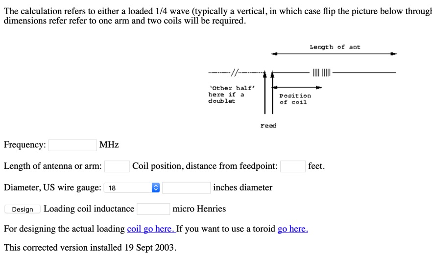 The calculation refers to either a loaded 1/4 wave or a loaded dipole,
 -
 The page provides detailed instructions on how to build a double bazooka antenna for the 40 meters band. It includes information on materials needed, measurements, and assembly steps. The antenna can be configured as an extended dipole or an inverted V, offering low noise, wide bandwidth, and a 1:1 standing wave ratio. The content also offers calculations for other bands and includes photos of the antenna fabrication process.
 -
 End-Fed Half-Wave Antennas (EFHWAs) are analyzed for their utility in portable QRP operations, emphasizing their simplicity, efficiency, and predictable radiation patterns compared to other portable antenna types. The discussion contrasts EFHWAs with vertical antennas, random length wires, and center-fed dipoles, highlighting the common pitfalls of each, such as ground system dependency for verticals and feedline issues for dipoles. The article details the electrical half-wavelength calculation using the formula L (Ft) = 468/F(MHz) and explains how EFHWAs can be resonant on harmonic frequencies, enabling multiband operation. Various deployment configurations are presented, including the inverted L, inverted Vee, sloping wire, and vertical setups, each with specific advantages for radiation angle and polarization. For instance, a vertical EFHWA offers a low angle of radiation suitable for DX contacts without requiring an extensive ground system. The resource also addresses the counterpoise requirements, suggesting a quarter-wavelength wire or connection to a metallic structure for decoupling. A schematic diagram for a simple parallel-tuned circuit tuner, based on the _Rainbow Bridge/Tuner_ design, is provided, detailing component values for 30 and 40 meters, including a 6 microhenry toroidal inductor and a 20-100 picofarad mica compression capacitor. The tuner's adjustment process for SWR matching is also outlined.
 -
 This calculator is designed to give the horizontal length of a particular dipole including Tees, antenna, or one side of it, for the frequency chosen. Enter the desired frequency and select the desired calculation from the drop box
 -
 Demonstrates the adaptation and construction of a 7-element DK7ZB Yagi antenna for the 4-meter band (70 MHz), utilizing components from a defunct 2-meter CUE DEE Yagi. The resource details the modifications made to the original DK7ZB design to fit the shorter CUE DEE boom length, specifically adjusting element lengths for 6mm rod elements while reusing existing mounting holes for the reflector and last director. It provides precise element lengths for the reflector, dipole (12mm aluminum tube), and five directors, along with a note on cutting elements for transport. The article includes a 4NEC2 simulation file for performance analysis and an SWR plot, confirming the antenna's electrical characteristics. It also specifies the calculation for the quarter-wavelength matching cable using SAT752F coaxial cable, resulting in a 909mm length. Practical application is shown with the finished antenna in operation at JO20XC, listing several activated Maidenhead squares such as JO56PA and JP40KS, validating its effectiveness for portable 70 MHz operations.
 -
 Designing and constructing portable wire antennas for HF operations, this resource explores several configurations including the _foldback dipole_ for space-constrained setups and an inductively shortened dual-band dipole for 20m and 40m. It details the calculation of inductance for shortened elements, providing a Visual Basic 6.0 program screenshot that illustrates determining coil parameters like turns and length for a **25.5 uH** inductor. The document emphasizes practical considerations such as adjusting wire lengths for optimal SWR, noting that a dual-band dipole achieved SWR below 2:1 on both 20m and 40m, with careful adjustment bringing it under 1.5:1. Further, the resource describes a half-wave antenna matched with a coaxial stub, a method often referred to as the _Fuchskreis_ in German amateur radio circles, to transform the high feedpoint impedance to 50 Ohms. This monoband solution, for a 20m application, uses a stub length of **2.98m** (0.216 lambda multiplied by coax velocity factor) and a shorted stub of approximately 48cm. The coaxial stub design is highlighted for its resilience to ground proximity, allowing it to be rolled up or laid on the ground with minimal SWR impact, making it highly suitable for portable QRP operations.
 -
 This web article details the construction of a 4-meter band coaxial dipole antenna, designed for operation between **70.000 MHz and 70.500 MHz**. The resource provides a bill of materials and step-by-step assembly instructions for a half-wave dipole constructed from _RG-58_ coaxial cable. The design specifies a direct 50 ohm feedpoint impedance, eliminating the need for an external matching network. Construction photographs illustrate the stripping and soldering processes for the coaxial cable elements, ensuring proper electrical connection and physical integrity. The article includes specific dimensions for the radiating elements, derived from calculations for the 70 MHz band. The project outlines the physical dimensions required for resonance at 70 MHz, with the outer braid forming one half and the inner conductor forming the other. The feedline connection is directly to the coaxial dipole's center, maintaining a 50 ohm characteristic impedance. While the article does not present SWR plots or VNA sweeps, it focuses on the mechanical construction and dimensional accuracy for achieving a functional 4-meter dipole. The design is intended for fixed station use, with no specific mention of polarization or height above ground, but implies a standard horizontal orientation for dipole operation. DXZone Focus: Web Article | 4m Coaxial Dipole | Construction Guide | 50 ohm Feed
 -
 This is a standard calculation method that can help you while tuning dipole antennas, by adjusting wire lengths. This method can be used also when you need to add lenght to your wires, and can be additionally used to quarter waves vertical antennas
 -
 The Tri-pole antenna, a clever modification of a standard dipole, allows for dual-band operation by integrating a third element. This design effectively shortens the overall dipole length by 10 to 20 percent, simplifying antenna rotation and offering a compact footprint. KK4OBI's article delves into the operational principles, using a 6 and 10-meter Tri-pole as a primary example, and provides comprehensive instructions for constructing any Tri-pole antenna within the 6 to 15-meter range. Key to the Tri-pole's performance is its off-center feed, necessitating a common mode choke at the feed point for optimal tuning and reduced noise. The author outlines a methodical approach to determining element dimensions, starting with a vertical element frequency calculated as 0.47 times the sum of the desired upper and lower band frequencies. This calculation, along with K-values derived from trend lines, guides the initial lengths for the horizontal arms, demonstrating how a 10m-6m Tri-pole can achieve a total horizontal length 78% shorter than a conventional 10-meter dipole. Tuning and balancing are critical, with the article detailing adjustments to arm lengths and the vertical element to achieve balanced SWR values, as validated through 4NEC2 simulations. Radiation patterns are analyzed at various elevations, showing gains around 5.7 dBi and favorable take-off angles for DX contacts. Construction details specify aluminum tubing dimensions, U-bolts, and an SO-239 connector, emphasizing the importance of a ferrite-based choke for wideband operation.
 -
 This page delves into the Inverted V antenna, a source of myths among ham radio operators. The author explores the behavior of this antenna type with a focus on a 20m half-wave dipole positioned 10m above the ground. From Pythagoras to high school math, the article simplifies the calculation of dimensions and angles for setting up an Inverted V antenna. It includes a spreadsheet for calculating hypotenuse length and angles, crucial for antenna setup. Additionally, it provides insight into the radiation pattern of a 'flat' half-wave dipole at 10m height. Useful for hams planning to optimize their antenna setup. In Norwegian.
 -
 Here is a formula and calculator for creating a loaded (shortened) quarter wave vertical or balanced dipole. The calculation refers to either a loaded 1/4 wave or a loaded dipole
 -
 This article describes the construction of a 9,50 m long dipole for the 30 m band (10.1 MHz to 10.15 MHz). It was designed to be mounted ca. 6Â m above ground inside an attic. The calculations were performed by OE1MEW
 -
 The HB9CV antenna calculator aids amateur radio enthusiasts in designing antennas for VHF and UHF bands. By inputting the working frequency, users can obtain crucial dimensions like dipole lengths and distances. The tool, based on the HFSS antenna model, provides data on impedance, VSWR, and gain, optimizing front/back radiation ratios. It includes tips for fine-tuning using a Г-matching balun and compensating capacitor, ensuring effective performance and minimal VSWR for enhanced radio communications and direction finding.
 -
 Online antenna calculator for a basic 3 elements yagi uda directional antenna. The described antenna design offers a front-to-back ratio of at least 20 dB, a gain exceeding 7.3 dBi, and a bandwidth (SWR < 2) of approximately 7% around the center frequency. It has an input impedance of 50 ohms when using a straight split dipole, which can be substituted with a folded dipole of the same length, increasing the impedance to 200 ohms. A matching balun is required for coaxial feeder connection, and the boom should be made of a dielectric material, like wood.
 -
 This article explores the powerful features of AutoEZ as an Excel application working with EZNEC antenna modeling software. The article demonstrates how variables, equations, and formulas enable versatile antenna design and automatic optimization. Through practical examples including dipoles, inverted vees, delta loops, and monopoles, the author shows techniques for achieving resonance, implementing transmission line resonators for broadbanding, and optimizing antennas across frequency ranges. The step-by-step demonstrations cover unit conversion, coordinate calculations, segmentation considerations, and SWR optimization. This practical guide illustrates how AutoEZ extends EZNEC's capabilities, making complex antenna modeling more efficient and accessible.
 -
 This project outlines a simple, cost-effective 40m band HF dipole antenna design, ideal for beginners. Constructed with insulated copper wire and a 1:1 balun, it offers a 50-ohm impedance, suitable for both 40m and 15m bands due to the harmonic relationship. Calculations account for a K factor, ensuring optimal length and performance. Antenna modeling with 4NEC2 confirms practical access to both bands, though real-world results may vary. Lightweight materials and straightforward assembly make it an accessible and versatile amateur radio solution.
 -
 This page provides a detailed example of the modeling and analysis of an 80m delta dipole antenna with a 600-ohm bifilar feedline. The model is based on antennas used by the RAF from 1940 to 1970. It covers the original model specifications, conductor mass calculations, resonance frequency observation, geometry adjustment steps, and final antenna dimensions. The content includes theoretical formulas, resonance frequency calculations, and practical steps for adjusting the antenna for optimal performance. Overall, it serves as a practical guide for hams looking to understand and optimize the performance of a delta dipole antenna for the 80m band.