Search results
Query: coax antenna traps
Links: 15 | Categories: 0
-
 A new perspective on the analysis and design of this popular antenna element. By Karl-Otto Muller, DG1MFT
 -
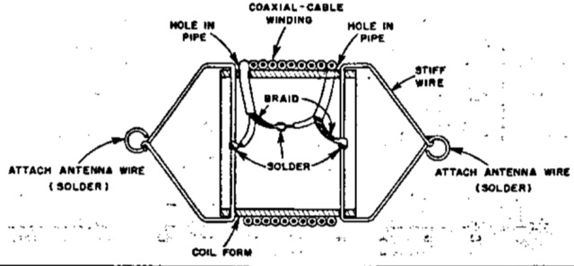
 This page describes the design and construction materials W8WWV used to build a coaxial cable trap. A coaxial cable trap is a parallel resonant circuit that is usually inserted in an antenna element to enable multiband operation.
 -
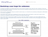
 This improved multiband trap dipole introduces a new trap design and a change in trap location. The antenna features double-coaxial-cable-wound traps having lower reactance and a higher quality factor (Q) than earlier coax-cable traps by W8NX
 -
 A rotary trapped-dipole for 17 and 20 meters, as described by IZ7ATH, presents a practical solution for multi-band HF operation. The author, Talino, recounts his experience building this antenna for IK7ZCQ, detailing the evolution from an initial concept involving a grounded-driven element and gamma-match to a direct-fed, non-grounded design. His pragmatic approach, adapting available materials, is evident throughout the construction narrative, particularly with the use of eight tapered aluminum pipes for the driven element. Construction specifics include precise measurements for the aluminum tubing, with diameters ranging from 30 mm down to 16 mm, and a critical note on reducing tip thickness for weight optimization. The _traps_, initially a concern, are fabricated using 8 turns of RG58 coax on a 27 mm support, tuned to resonate at 18.1 MHz using a dip-meter. Talino emphasizes sealing the traps with RF glue and PVC tape to prevent water ingress, a crucial step for longevity. Field test results, conducted on a 10-meter pole in a clear garden environment, showed an SWR of 1.2:1 on 17 meters and 1.5:1 at 14.200 MHz. While SWR varied slightly when installed at Mario's QTH due to nearby objects, the antenna's performance remained commendable. The final half-dipole length is 46 cm for the 18 MHz tips, and the total weight is under 6 kg, with potential for further reduction.
 -
 The 6 Band Inverted L Antenna MK3 is a versatile multiband antenna designed for amateur radio operators. This antenna covers 160m, 80m, 40m, 20m, 15m, and 10m bands, making it suitable for a wide range of HF communications. The design is based on a W3DZZ configuration, incorporating traps for optimal performance. The MK3 version features a sturdy 5/8th CB mast, replacing the original timber mast, which enhances durability against harsh weather conditions. The antenna's construction allows for effective operation, particularly on the 40m band, where it has been successfully used to contact distant locations including ZL, VK, and Antarctica. Constructing this antenna requires careful attention to detail, especially regarding the radials and grounding. The traps resonate at specific frequencies, and additional resources are available for building coaxial traps. The antenna is designed to work efficiently without an ATU on the lower bands, while higher bands may require tuning. This project is ideal for both beginner and intermediate operators looking to enhance their station with a reliable multiband antenna.
 -
 Testing and comparison of traps and trap antennas
 -
 The problem with making your own trapped HF antennas is usually getting the coaxial traps tuned to frequency.
 -
 Analysis of an antenna trap where a coil is formed of a length of coax cable, the outer conductor of one coax end is tied to the inner conductor of the other coax end, and the remaining connections form the terminals for the trap.
 -
-
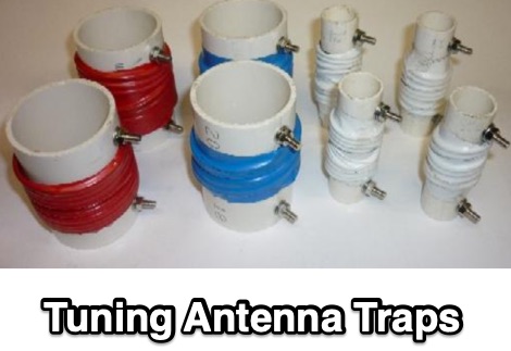 The problem with making your own trapped HF antennas is usually getting the coaxial traps tuned to frequency. This article explains a method using a RF signal generator at +10dBm output into the coaxial trap.
 -
 Constructing a dual-band antenna for 40 and 20 meters often involves compromises in size or complexity. This resource presents a compact _open sleeve dipole_ design that addresses these challenges by using 450-ohm ladder line and folded elements to achieve a total length of approximately **17.17 meters**, significantly shorter than a full-size 40-meter dipole. The design leverages electromagnetic coupling, where a primary radiator handles the 40-meter band, and a second conductor resonates on 20 meters without direct electrical connection. This configuration eliminates the need for traditional traps, loading coils, or switching components, simplifying construction and reducing potential loss points. The antenna is fed with RG-58C/U coaxial cable, and a common-mode choke is recommended at the feed point to suppress sheath currents, ensuring a cleaner radiation pattern and minimizing RF in the shack. The design is well-suited for portable operations, field deployments, temporary installations, and restricted urban environments where space is a premium, offering solid performance on both HF bands.
 -
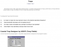
 A document that will guide you on Coaxial-Cable trap optimization process to gain on global antenna performance and on increasing effective bandwidth.
 -
 This document provides comprehensive guidance on modeling and constructing multiband dipole antennas using traps. It addresses common segmentation issues in EZNEC modeling software, recommends optimal segment lengths for trap models, and compares trapped dipoles with paralleled multiband dipoles. While trap dipoles are significantly shorter, they exhibit lower gain and narrower bandwidth. Detailed instructions for building weatherproof coaxial traps include material lists, construction steps, and tuning methods. The guide notes that properly constructed coaxial traps introduce only minimal signal loss (0.6 dB) while offering practical multiband performance in a compact design.
 -
 Learn how an experienced ham radio operator rebuilt his trap dipole antenna for 30, 40, and 80 meters after a storm damage. Discover the process of upgrading to a short trap dipole for 40, 80, and 160 meters using double-wound traps made from RG-58 coax. Follow along for construction details and tips on building this unique classi.
 -
 The tri-band trapped delta loop antenna design operates on 80 meters (3.5–4 MHz), 40 meters (7–7.3 MHz), and 30 meters (10.1–10.15 MHz) using a single triangular wire loop. This configuration eliminates the need for an external antenna tuner or band-switching relays. The antenna's physical perimeter, approximately 270 feet, establishes 80M as the fundamental band, with specific trap placements enabling resonance on 40M and 30M. Trap design and placement are critical, with 30M traps positioned inboard of 40M traps within the horizontal element. Each slant leg measures approximately 80 feet. The resource references foundational information from the _ARRL Antenna Handbook_ and _ON4UN’s Low Band DXing_ regarding full-wave loop behavior and feedpoint impedances. The project aims to provide multi-band HF operation from a single, fixed antenna structure.