Search results
Query: dipole loading coil
Links: 12 | Categories: 0
-
 Portable, and shortened with loading coils rotatable dipoles for 6 meters, 20 meters and multibands.
 -
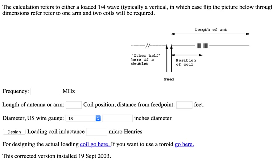 The calculation refers to either a loaded 1/4 wave or a loaded dipole,
 -
 An inverted V antenna for 40-80 with loading coils. This antenna is a full size on 40 and a shortened 80 by KG0ZZ.
 -
 Presents a construction project for a linear-loaded 40-meter rotatable dipole, detailing the design evolution from mid-element coils to 300-ohm twinlead loading. It covers material selection, including repurposed fishing poles and EMT conduit, and outlines the assembly process for the antenna elements and mounting plate. The resource provides specific measurements for element lengths and linear loading sections, along with SWR plots demonstrating the antenna's resonance at 7.035 MHz with a 1.1:1 SWR, and bandwidth up to 7.120 MHz below 2:1 SWR. The article documents the antenna's performance during various RTTY and CW contests, including the SARTG RTTY and SCC RTTY contests in August 2006, and the ARRL DX CW and CQWW WPX RTTY contests in February 2007. It reports successful operation at 500-1000W, noting improved performance after replacing a faulty coax cable. Specific DX contacts from British Columbia, including stations in Europe and South Africa, are listed, illustrating the antenna's capability despite its shortened length and relatively low height of 55 feet. The content highlights practical considerations such as weatherproofing the connections and supporting the fiberglass elements to prevent sagging. It also includes a brief comparison to an inverted-V at similar height and a ground-mounted vertical, noting the rotatable dipole's quieter reception. The author shares insights into the iterative design process and tuning adjustments made to achieve optimal resonance.
 -
 A 40/80 meters dipole made with two loading coils based on a project by IK1ZOY
 -
 Build an effective dipole antenna that needs much less space by adding two loading coils. This online calculator tells you how.
 -
 Demonstrating the construction of a short dipole antenna tailored for the 60 meter band, this resource provides detailed instructions for radio enthusiasts with limited space. The design incorporates inductive loading using two inductors (L1/L2) made from PVC tubes, allowing for effective operation on 5 MHz. The antenna consists of 12 meters of wire, divided into four sections, with specific dimensions and materials outlined for optimal performance. Results from users indicate that this antenna can significantly enhance DXing capabilities on the 60 meter band. Feedback from operators suggests that while the design is effective, adjustments may be necessary based on individual setups, such as coil diameter and wire gauge. Many users report successful construction and operation, with some experimenting with variations to improve resonance. The practical application of this antenna design has led to successful contacts and improved signal quality, making it a popular choice among 60 meter band operators.
 -
 The Superantennas MP-1 portable HF antenna is analyzed for its design and field performance, particularly its high-Q loading coil and 3/8-inch mounting. The review details the antenna's construction, including an 8-inch vertical section, a large-diameter loading coil tuned by a sleeve, and a 4-foot whip that disassembles into six rods for transport. Initial testing with the supplied 10-foot ribbon cable "ground plane" yielded poor SWR and RF hot conditions, indicating an inadequate ground system. Further experimentation with longer radials and resonant counterpoises for each band improved matching and eliminated RF hot issues, but introduced significant operational complexity. The author notes the difficulty in optimizing both counterpoise length and coil setting without an antenna analyzer, and the sensitivity of the MP-1 to counterpoise deployment. The review also discusses the recommendation to tune for maximum received signals rather than minimum SWR, often necessitating an external ATU due to the antenna's typical low impedance. The **MP-1**'s critical dependence on resonant counterpoises for effective operation, especially when elevated, is highlighted as a major drawback for portable use. The author ultimately sold the antenna, concluding that despite its sound technical design, its fussy nature and the need for extensive counterpoise management or an ATU detract from its portability and convenience compared to simpler, less expensive dipole solutions. The **Superantennas MP-1** is deemed a flawed portable antenna, requiring considerable effort to achieve its claimed performance.
 -
 This article demonstrate how to build and mount a 40 meter loaded dipole using basic materials. This antenna reduce the overall length of an HF dipole through the use of loading coils.
 -
 Constructing a dual-band antenna for 40 and 20 meters often involves compromises in size or complexity. This resource presents a compact _open sleeve dipole_ design that addresses these challenges by using 450-ohm ladder line and folded elements to achieve a total length of approximately **17.17 meters**, significantly shorter than a full-size 40-meter dipole. The design leverages electromagnetic coupling, where a primary radiator handles the 40-meter band, and a second conductor resonates on 20 meters without direct electrical connection. This configuration eliminates the need for traditional traps, loading coils, or switching components, simplifying construction and reducing potential loss points. The antenna is fed with RG-58C/U coaxial cable, and a common-mode choke is recommended at the feed point to suppress sheath currents, ensuring a cleaner radiation pattern and minimizing RF in the shack. The design is well-suited for portable operations, field deployments, temporary installations, and restricted urban environments where space is a premium, offering solid performance on both HF bands.
 -
 A 60-foot available space, for example, might necessitate a shortened multiband dipole array to cover 80, 40, and 15 meters effectively. This resource details the construction of such an antenna, combining full-size and coil-loaded dipoles on a single feedline. It addresses the common challenge of fitting multiple HF bands into restricted physical footprints, providing practical guidance for hams with smaller backyards or portable operations. The core of the offering is an interactive calculator that determines required loading coil inductance and dipole lengths for various amateur bands from 160m to 10m. Users input their available space, and the tool provides dimensions, coil turns, and an efficiency rating (Good or Fair) based on the antenna's electrical length relative to a quarter-wavelength. It also suggests suitable _PVC_ pipe diameters for coil forms. The article further illustrates a center feed-point assembly using an 18-inch section of 2-inch _PVC_ pipe, detailing eye-bolt spacing and coaxial connector installation. It emphasizes the importance of adequate spacing between parallel dipoles and offers customization options for the feed-point, including the addition of a _Balun_ for improved feedline isolation.
 -
 This document outlines the construction of a homebrew Buddipole antenna variant, designed for portable use and emergency services. The antenna utilizes telescoping whips and loading coils, enhancing its versatility across various HF bands. Key components include fiberglass rods, brass fittings, and Anderson Power Pole connectors, ensuring robust electrical connections. The design emphasizes non-inductive materials to minimize interference, while practical assembly techniques, such as epoxy and heat shrink tubing, are employed for durability. This variant aims to improve upon traditional Buddipole designs, offering greater strength and functionality.