Search results
Query: end fed dipole
Links: 43 | Categories: 1
Categories
-
 This PDF article from April 2001 QST details the construction of the "NJQRP Squirt," a reduced-size 80-meter inverted-V dipole antenna. The resource provides a general construction sketch, a photograph of the assembled antenna, and specific dimensions for PC-board insulators. The antenna consists of two wire legs, each approximately **34 feet long**, separated by 90 degrees, fed at the center. It is designed for operation on 80 meters (3.5-4.0 MHz) as a quarter-wavelength antenna, requiring a low-loss feedline and an external antenna tuner due to its non-resonant feedpoint impedance. Construction utilizes readily available materials, including 1/16-inch glass-epoxy PC board for end and center insulators, and #20 or #22 insulated hookup wire for the elements. The feedline specified is 300-ohm TV flat ribbon line, with a note on potential trimming for tuner compatibility. N2CX reports the antenna's center should be elevated to at least **20 feet**, with ends no lower than seven feet above ground, resulting in a ground footprint of approximately 50 feet wide. The design prioritizes NVIS propagation for local 80-meter contacts. DXZone Focus: PDF Article | 80m Inverted-V Dipole | Construction Notes | 34 ft element length
 -
 Details the construction of a J-vertical antenna specifically for the 10-meter band, offering a practical alternative to a _Slim Jim_ design for 28 MHz. The resource outlines the use of aluminum tubing for the half-wave vertical section and coaxial cable for the quarter-wave matching section, providing specific calculations for element lengths based on frequency and coaxial cable velocity factor. It contrasts the performance of the J-vertical with center-fed dipoles and end-fed verticals, noting superior results in previous comparisons. The article further presents a more recent iteration of the J-vertical, constructed using a fiberglass pole and insulated wire, with updated dimensions for 28.8 MHz. It includes practical advice on weatherproofing connections and securing the antenna for durability against adverse conditions, referencing the survival of an original _J Vertical_ during 110 MPH winds in 1987. The SWR performance is reported as 1.1:1 at 28.6 MHz, maintaining below 1.5:1 across 28.3 to 29 MHz.
 -
 G5RV 40m Beam Antenna. Adding a 28 ft. piece of vertical wire to one end of a 102 ft. center-fed dipole turns it into a 40m beam with a very wide beamwidth
 -
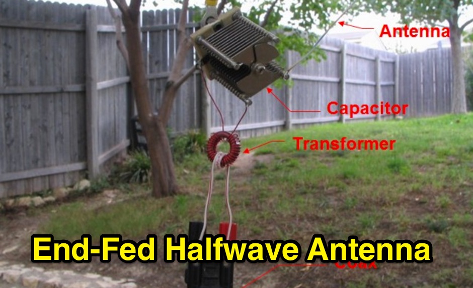 The end-fed halfwave antenna is a resonant half wavelength long antenna like a dipole antenna except for it is fed at its end rather then in the center. This antenna is as old as radio and is probably best known as the Zepp Antenna
 -
 A dual-bander for 80M and 40m. An Extended Double Zepp (EDZ) is a 5/4 wavelength center-fed dipole. This article will introduce the Half-Extended Double Zepp (HEDZ) which has characteristics that a lot of amateur radio operators should find quite interesting
 -
 This drawing shows a simple 10 meter wire J-pole antenna designed for 28.4 MHz. It is a vertical, end-fed Zepp-style antenna made from common materials and intended for easy home construction. The main radiating element is a straight length of stranded copper wire, either 14 or 18 gauge, cut to about 16.5 feet. At the top, the wire is supported by an insulator, allowing the antenna to be hoisted vertically. The matching section is made from 450-ohm ladder line, approximately 7 feet 9.5 inches long, and shorted at the bottom. This matching stub transforms the impedance so the antenna can be fed with coaxial cable. The feed point is tapped about 6 inches above the bottom of the stub, with the shield and center conductor connected at the proper points. A choke balun is formed with five turns of RG-58 coax in a 4-inch diameter loop to help reduce unwanted RF on the feed line. The drawing notes that this antenna has about 0 dBd gain, similar to a dipole, but offers an omnidirectional pattern and low-angle radiation when installed high. Its main advantage is practical performance, simple construction, and effective coverage for 10 meter operation.
 -
 This type of antenna has same performance as a dipole, but requires only one single mounting point
 -
 A rotary trapped-dipole for 17 and 20 meters, as described by IZ7ATH, presents a practical solution for multi-band HF operation. The author, Talino, recounts his experience building this antenna for IK7ZCQ, detailing the evolution from an initial concept involving a grounded-driven element and gamma-match to a direct-fed, non-grounded design. His pragmatic approach, adapting available materials, is evident throughout the construction narrative, particularly with the use of eight tapered aluminum pipes for the driven element. Construction specifics include precise measurements for the aluminum tubing, with diameters ranging from 30 mm down to 16 mm, and a critical note on reducing tip thickness for weight optimization. The _traps_, initially a concern, are fabricated using 8 turns of RG58 coax on a 27 mm support, tuned to resonate at 18.1 MHz using a dip-meter. Talino emphasizes sealing the traps with RF glue and PVC tape to prevent water ingress, a crucial step for longevity. Field test results, conducted on a 10-meter pole in a clear garden environment, showed an SWR of 1.2:1 on 17 meters and 1.5:1 at 14.200 MHz. While SWR varied slightly when installed at Mario's QTH due to nearby objects, the antenna's performance remained commendable. The final half-dipole length is 46 cm for the 18 MHz tips, and the total weight is under 6 kg, with potential for further reduction.
 -
 K4TR Manufacture and sell simple dipoles, half square 2 wire phased vertical arrays, end fed zepp antennas, G5RV antennas. 1:1 baluns
 -
 A Center-Fed Half-Wave Dipole is probably the simplest of antennas to construct and use. It is usually suspended between two supports, from it's end insulators, and has the feedline hanging from the center.
 -
 End-Fed Half-Wave Antennas (EFHWAs) are analyzed for their utility in portable QRP operations, emphasizing their simplicity, efficiency, and predictable radiation patterns compared to other portable antenna types. The discussion contrasts EFHWAs with vertical antennas, random length wires, and center-fed dipoles, highlighting the common pitfalls of each, such as ground system dependency for verticals and feedline issues for dipoles. The article details the electrical half-wavelength calculation using the formula L (Ft) = 468/F(MHz) and explains how EFHWAs can be resonant on harmonic frequencies, enabling multiband operation. Various deployment configurations are presented, including the inverted L, inverted Vee, sloping wire, and vertical setups, each with specific advantages for radiation angle and polarization. For instance, a vertical EFHWA offers a low angle of radiation suitable for DX contacts without requiring an extensive ground system. The resource also addresses the counterpoise requirements, suggesting a quarter-wavelength wire or connection to a metallic structure for decoupling. A schematic diagram for a simple parallel-tuned circuit tuner, based on the _Rainbow Bridge/Tuner_ design, is provided, detailing component values for 30 and 40 meters, including a 6 microhenry toroidal inductor and a 20-100 picofarad mica compression capacitor. The tuner's adjustment process for SWR matching is also outlined.
 -
 Design your owm HF shiortened dipole. Includes a diagram of a lumped-constant loaded dipole antenna that is intended to fit in available space, rather than requiring a full 1/2 wavelength, at a specified frequency
 -
 A 11 pages pdf file about monoband or multiband end fed half wave vertical antenna that is great for DX and very cheap to build by Steve G0KYA
 -
 Connecting centre fed antennas, dipoles, yagis, rhombics, loops to coaxial cable, unless care is taken, it is not difficult to end up with feeder radiation resulting in power loss and the radiation characteristics changes
 -
 Ham radio antennas and electronics, specialized in 1/2 wave dipole, OCF dipole, windom, full wave loop, end fed, inverted L, portable end fed antenna, long wire, SWL antenna, fan dipole, multiband dipole, G5RV and military antennas.
 -
 The G5RV multiband HF antenna, designed by Louis Varney (G5RV) in 1946, is a popular compromise antenna offering good overall performance on most HF bands when paired with an external antenna tuner. The basic full-size G5RV measures 102 feet across the top for 80 through 10 meter operation and is fed at the center via a 34-foot low-loss feed-stub. This interaction between the radiating section and the feed-stub facilitates matching across 80-10 meters with a standard tuner, often eliminating the need for ladder line directly to the shack. The antenna's design center frequency is 14.150 MHz, configured as a 3/2-wave dipole on 20 meters, with its 102-foot length derived from long-wire antenna formulas. Construction details emphasize the matching section, which can be open wire, ladder line (window-type), or TV twin lead. Each type has a specific velocity factor (VF) affecting its physical length for an electrical half-wave on 14 MHz; for instance, open wire requires 33.7 feet (VF 0.97), ladder line 31.3 feet (VF 0.90), and TV twin lead 28.5 feet (VF 0.82). The article provides formulas for calculating these lengths and discusses the antenna's behavior on individual bands, from 3.5 MHz where it acts as a shortened dipole, to 28 MHz where it functions as two three-half-wave long-wire antennas fed in-phase. Practical construction notes include recommendations for vertical descent of the matching section, sealing the coax junction, providing strain relief, and winding a coaxial choke coil to mitigate common mode current. The resource also presents dimensions for double-size (204 ft) and half-size (51 ft) G5RV versions, along with their corresponding matching section lengths for various line types, making it a versatile reference for hams considering this classic wire antenna.
 -
 Centre fed half wave dipoles make great, simple and effective antennas for the HF bands. Sometimes however, the centre feed is not ideal. This great project will improve the overall antenna performance.
 -
 A simple and awesome wire monoband antenna, very usefull for portable and dxpeditions usage, consist of two elements, a driver and the reflector. This endfed halfwave gives a very low take off angle and is very suited for chasing DX.
 -
 This antenna is intended for the 20-meter Band. There are two Voltage Fed Helical Dipoles, made with 2 slinky that fed with phase shift in 90 degree
 -
 This resource details the four primary functions of a ground system: lightning energy dispersion, equipment safety, RF return path provision for end-fed antennas, and management of induced RF currents. It clarifies that a ground system's effectiveness varies depending on its specific function, noting that a good lightning ground might not be an effective RF ground. The content emphasizes that proper antenna system design, including baluns and appropriate feedline lengths, often negates the need for an RF station ground to mitigate common mode currents or RFI in the shack. The article quantifies lightning energy, stating its peak is in the dozens or hundreds of kilohertz, with damaging energy extending to hundreds of megahertz, and currents reaching thousands of amperes. It recommends solid, wide, smooth copper surfaces for ground leads to achieve low impedance across a wide frequency range. The author, W8JI, shares practical insights from his station, which includes two 300-ft towers and four 130-ft wire verticals, detailing his use of common point grounds and _DX Engineering RR-8 HD_ antenna switches for lightning protection without coaxial surge protectors. Specific examples of antenna systems prone to common mode current problems are listed, such as random wire antennas without proper feedline lengths and off-center fed dipoles. The text also explains how a ground screen or radial system can reduce local noise sensitivity for vertically polarized antennas by covering the lossy earth.
 -
 The X80 multi-band HF vertical antenna, a commercial iteration of the Rybakov design, exhibits a physical length of 5.5 meters, or approximately 18 feet, and is constructed from aluminum tubing. It operates as a non-resonant vertical, requiring an external antenna tuner for impedance matching across its intended operating frequencies. The antenna's design incorporates a 1:4 UNUN at its base, facilitating a nominal 50-ohm feed point impedance for the coaxial cable. Performance observations indicate effective operation on 40 meters, 20 meters, 15 meters, and 10 meters, with reduced efficiency on 80 meters and 160 meters due to its relatively short electrical length for these lower bands. Comparative analysis with a G5RV dipole and a half-wave end-fed antenna reveals the X80 offers a lower take-off angle, beneficial for DX contacts, particularly on the higher HF bands. Field tests conducted with an Icom IC-706MKIIG transceiver and an LDG AT-100ProII autotuner demonstrate the X80's ability to achieve acceptable SWR across 80m through 10m. The antenna's compact footprint and ease of deployment make it suitable for restricted spaces or portable operations, though its performance on 80 meters is noted as a compromise compared to full-size resonant antennas.
 -
 This web article by VK3BLG details the construction of an experimental 70cm (432 MHz) circularly polarized patch antenna, intended for satellite communication. The resource provides dimensions, feed point specifications, and impedance matching considerations for a single patch element, with discussion extending to array configurations for circular polarization. Construction involves a copper patch element on a dielectric substrate, fed via a coaxial cable. The design is based on information derived from AO-40 satellite antenna specifications, focusing on achieving circular polarization for satellite reception. The article includes specific dimensions for the patch and feed points, along with impedance values. Validation is implied through on-air satellite reception reports, with initial signal reports of **1 S-point above noise** for AO-40 beacons using a grid reflector, improving to **3-4 S-points above noise** with a 2-turn helical feed. The author references a _NanoVNA_ for impedance measurements and discusses the relationship between slot and dipole antennas in the context of patch design. DXZone Focus: Web Article | 70cm Patch Antenna | On-Air Satellite Reception | Circular Polarization
 -
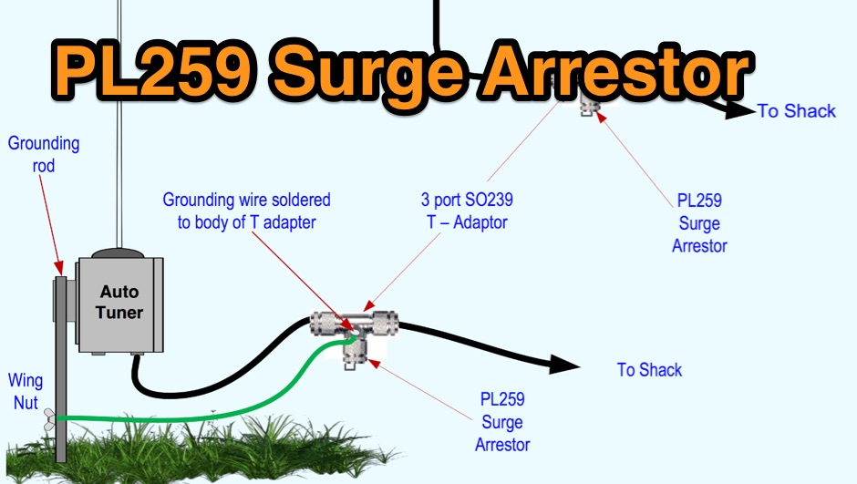 Limiting static surges on dipoles, verticals or end fed antennas
 -
 The HF horizontal loop has been around for many years now. This article includes a YouTube video and discusses the reasons for looking at this antenna, its design, and its installation. There are some on-air comparisons against three regular double bazooka (coax) dipoles and the Par SWL End-Fed antenna.
 -
 A wire antenna feeded with an unsymmetrical feed and a 1:4 balun can be tuned from 6 to 80 meters band but can be noisier than a dipole and cause RF in the shack
 -
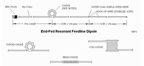 Experiences with the end-fed dipole based on the concepts presented by J. Taylor in an article titled RFD-1 and RFD-2: Resonant Feed-Line Dipoles in QST. August 1991.
 -
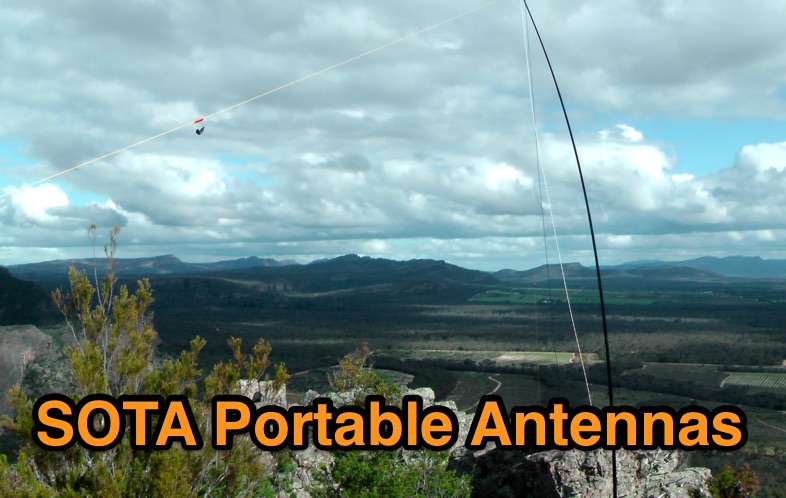 A review of some portable antennas for SOTA operations, including linked dipoles, end-fed, verticals
 -
 Operating a ham station often involves encountering radio frequency interference (RFI), RF feedback, or RF burns, which are frequently misattributed to poor equipment grounding. This resource meticulously dissects these assumptions, asserting that RF grounds on the operating desk often merely mask more significant system flaws. It identifies five primary causes for RF problems, including antenna system design flaws, proximity of the antenna to the operating position, DC power supply ground loops, equipment design defects, and poorly installed connectors or defective cables. The content emphasizes that issues like "hot cabinets" or changes in SWR when connecting a ground indicate substantial RF flowing over wiring or cabinets, a phenomenon known as common-mode current. The article provides detailed explanations of common-mode current generation, particularly from single-wire fed antennas like longwires, random wires, and OCF dipoles, which inherently present high levels of RF in the shack. It also illustrates how vertical antennas, lacking a perfect ground system, can excite feed lines with significant common-mode current. Through simulations, the author demonstrates how a dipole without a proper _balun_ can cause RF problems at the operating desk, showing current patterns and voltage distributions on feed line shields. The discussion extends to the proper application of _RF isolators_ and _ferrite beads_, clarifying their role in modifying common-mode impedance on cable shields and cautioning against their use as a band-aid for fundamental system defects. The resource advocates for correcting the actual source of RF problems, such as antenna system issues or poor connector mounting, rather than relying on internal shack grounding or isolators. It highlights that properly functioning two-conductor feed lines, like coaxial or open-wire lines, should result in minimal RF levels at the operating position, even without a desk RF ground. The author shares personal experience, noting that his stations since the late 1970s have operated without RF grounds at the desks, relying instead on proper antenna system design and feed line integrity.
 -
 Amateur radio antennas manufacturer based in Italy. Produces HF end-fed, dipoles, and other wire antenna types, mono band and multi band antennas.
 -
 The ZS1J/B beacon operates on 28.2025 MHz with 5 Watts output to a half-wave, end-fed vertical antenna, initially installed in 1977 as ZS5VHF near Durban. The 10-meter transmitter is a modified 23-channel CB radio, and the identification keyer uses a diode matrix unit with TTL ICs from the same era. After relocation to Plettenberg Bay in 1993, the beacon has been in continuous service, with additional QRP transmitters later installed for other bands. In 1994, a single-transistor, 80-meter, 0.5-watt QRP transmitter with a half-wave dipole was added on 3586 kHz, followed by a 160-meter, 0.5-watt unit on 1817 kHz. A 30-meter, 0.5-watt transmitter was installed in 1996, operating on 10.124 MHz. In 2002, a 40-meter QRRP beacon on 7029 kHz, with an output of 100 microwatts, achieved DX reports up to 1100 km from ZS6UT in Pretoria. Best DX reports for the 80m and 160m beacons came from 9J2BO.
 -
 This type of antenna is a popular antenna design as the performance is very good across the HF bands and requires little or no tuning. It’s a dipole fed off center with a 4:1 balun at the offset feed point. The antenna shown covers 80, 40, 20 and 10 meters. The formula can also be used to adjust the overall length to cover more or fewer bands and the resulting overall length. 160-10m, 80-10m or 40-10 meters depending on your available space. Other bands will require a tuner.
 -
 Constructing a dual-band antenna for 40 and 20 meters often involves compromises in size or complexity. This resource presents a compact _open sleeve dipole_ design that addresses these challenges by using 450-ohm ladder line and folded elements to achieve a total length of approximately **17.17 meters**, significantly shorter than a full-size 40-meter dipole. The design leverages electromagnetic coupling, where a primary radiator handles the 40-meter band, and a second conductor resonates on 20 meters without direct electrical connection. This configuration eliminates the need for traditional traps, loading coils, or switching components, simplifying construction and reducing potential loss points. The antenna is fed with RG-58C/U coaxial cable, and a common-mode choke is recommended at the feed point to suppress sheath currents, ensuring a cleaner radiation pattern and minimizing RF in the shack. The design is well-suited for portable operations, field deployments, temporary installations, and restricted urban environments where space is a premium, offering solid performance on both HF bands.
 -
 This antenna looks like an inverted L antenna, yet it is not, it could also be viewed as a 160m off-center fed dipole antenna, it looks more like an end-fed 1/4 wave 160 meter antenna.
 -
 Building an End-Fed Half-Wave (EFHW) antenna from a kit, as detailed by Frank Bontenbal, PA2DKW, with process photos by Bob Inderbitzen, NQ1R, offers a practical approach for hams. This specific kit, a collaboration between ARRL and HF Kits, targets 10, 15, 20, and 40 meters, making it a versatile option for HF operations. Unlike a center-fed dipole, the EFHW is a half-wavelength antenna fed at one end, which simplifies deployment, particularly for portable use. The construction guide meticulously outlines the assembly of the 49:1 impedance matching network, crucial for transforming the antenna's high impedance (around 2,500 Ohms) to a transceiver-friendly 50 Ohms. Steps include preparing the enclosure by drilling holes for the coaxial connector and antenna connections, followed by the precise winding of enameled copper wire onto a toroid to create the transformer. The guide emphasizes careful insulation removal and soldering for reliable connections. Final assembly involves integrating a 100 pF capacitor for higher band compensation, soldering the transformer's primary and secondary sides, and conducting SWR tests with a 2K7 resistor or a half-wavelength wire. The document also provides examples of wire lengths for different bands, such as 16 feet for 10 meters or 66 feet for 40 meters, demonstrating the transformer's adaptability for various half-wavelength configurations.
 -
 This article discusses suitable first HF antenna options for amateur radio operators with limited space. It recommends an Off-Center Fed (OCF) Dipole and a Vertical Dipole, detailing the installation processes, considerations for stealth and ease of setup, and the characteristics that make them ideal for newcomers. Safety warnings and maintenance tips are provided to ensure effective and secure operation.
 -
 This document details the construction of a multi-band end-fed antenna, suitable for situations with limited space for larger antennas. The design utilizes a 1:49 to 1:60 impedance transformer to match a half-wave wire antenna fed at one end. Compared to a traditional dipole, this antenna resembles a highly unbalanced Windom antenna with one very long leg and a virtual short leg. The design eliminates the need for radials but relies on the coax cable shield for grounding. The document recommends using at least 10 meters of coax and installing a common mode filter at the entry point to the shack for improved performance.
 -
 This article describes the construction of a simple dual-band VHF/UHF end-fed vertical dipole antenna designed for local repeater access using an Icom IC-705 radio. Built from a single piece of RG58U coaxial cable, the antenna consists of a 460mm exposed inner conductor, 450mm of intact coax, and a 9-turn choke balun wound on a 27mm former. Mounted on a 10m Spiderpole, the antenna achieves excellent SWR readings (<1.2:1 on 2m, <1.5:1 on 70cm) and provides effective coverage of local repeaters with unexpected reach into distant locations.
 -
 The article describes the construction of a 1:49 impedance transformer designed to match the high impedance (around 2500Ω) of an end-fed half-wave (EFHW) dipole antenna to the 50Ω impedance of a typical transceiver. The EFHW is a popular portable antenna due to its simple construction, but feeding it can be challenging compared to a center-fed dipole. The transformer was built using an FT240-43 ferrite toroid core, with 2 primary and 14 secondary windings for a 1:49 impedance ratio. A capacitor was added in series with the primary winding to improve performance at higher frequencies. The author compared versions with one and two cores, and found that 100pF worked best for the single core design while 200pF was optimal for the dual core transformer.
 -
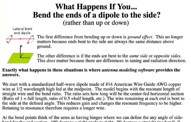 Discussion about laterally bent-end dipoles. Bent by percentage of length and fine-tuned by angling the bent ends.
 -
 This page provides detailed instructions on refining an end-fed vertical dipole antenna for ham radio operators looking to improve their signal reception and transmission. The content offers practical tips and techniques for optimizing the performance of this specific type of antenna. The page is useful for hams who are interested in experimenting with different antenna designs and configurations to enhance their overall radio communication experience.
 -
 Andrew Georgakopoulos, SV1DKD, modeled the End-Fed Half Wave (EFHW) antenna using MMANA-GAL software. He evaluated the EFHW-8010-2K from Myantennas.com for field operations, comparing it to random wires, OCFD, and dipole antennas. His results showed similar performance to OCFD, confirming EFHW's practical feeding advantage but with potential high-voltage risks at the feed point
 -
 Fully functional weathervane conceals an efficient 2- meter base-station antenna. Your Neighbors and HOA won’t know it’s there and they will love the rooster-vane. The Rooster-Tenna is a covert 2-meter ham radio antenna disguised as a functional weathervane, ensuring seamless integration into residential environments. This improved version features a wide-spaced parallel-fed folded dipole in a compact skeleton slot design. Constructed from aluminum tubing and acrylic supports, it offers omnidirectional, vertically polarized performance suitable for repeater and satellite use. Easy to mount and tune, it achieves a low SWR across the 2m band. With 3D-printable parts available, the Rooster-Tenna blends practicality with stealth, making it an ideal solution for HOA-restricted areas
 -
 This presentation explores the practice of QRP (low-power) amateur radio operation in outdoor settings. It guides operators to identify their specific objectives for portable operations, which inform equipment and antenna choices. The discussion covers considerations including portability, operating modes, power requirements, and weather resistance. Various antenna designs are examined, from vertical configurations to dipoles and end-fed options, with emphasis on deployment practicality in public spaces. The presentation concludes with practical advice on selecting operating locations, RF safety, and resources for equipment and community support for QRP enthusiasts.