Search results
Query: fm filters
Links: 9 | Categories: 0
-
 The RigPix database entry provides a comprehensive technical overview of the Icom IC-746 amateur HF/VHF transceiver, detailing its operational parameters and physical characteristics. It specifies the transmit frequency ranges across 10-160 meters plus WARC bands, 50-54 MHz, and 144-146/148 MHz, alongside receive coverage from 0.03-60 MHz and 108-174 MHz. The resource outlines supported modes including AM, FM, SSB, CW, and RTTY, noting a tuning step resolution down to 1 Hz and a frequency stability of ±5 ppm. Key electrical specifications are presented, such as a 13.8 VDC power supply requirement, current drain figures for RX (1.8-2 A) and TX (Max 20 A), and RF output power ranging from 5-40 W for AM and 5-100 W for FM, SSB (PEP), and CW. The entry details the triple conversion superheterodyne receiver system, listing IF frequencies at 69.01 MHz, 9.01 MHz, and 455 KHz, along with sensitivity ratings for various modes and bands. Transmitter section specifics include modulation systems and spurious emission levels. Additional features like a built-in auto ATU, electronic keyer, simple spectrum scope, DSP, and CI-V computer control are noted. The page also lists related documents, modifications, and an extensive array of optional accessories, including various filters, microphones, and external tuners, providing a complete profile of the IC-746.
 -
 Constructing a functional spectrum analyzer for the 0-100 MHz range presents a significant challenge for radio amateurs, often requiring specialized components and careful calibration. This project details a homebrew spectrum analyzer design utilizing common integrated circuits like the _SA605D_ FM receiver IC and _MAR-6_ MMIC amplifiers, aiming for a cost-effective solution. The design incorporates a low-pass filter, RF amplification, a voltage-controlled oscillator (VCO) for downconversion, and multiple IF stages at 150 MHz and 10.7 MHz, with a resolution bandwidth (RBW) of 15 kHz. Critical components such as the _SBL-1_ mixer and varicap diodes are specified, alongside instructions for winding inductors and tuning filters. The analyzer's performance is discussed in terms of input level limitations, specifically the 1dB-compression point and third-order intercept point, to ensure accurate measurements and prevent component damage. The _SA605D_'s logarithmic Received Signal Strength Indicator (RSSI) output serves as the detector, driving the Y-input of an oscilloscope, while a _TL084_ op-amp generates the sweep signal for the X-input. Potential enhancements include adding a step attenuator, improving front-end filtering, and implementing switchable IF filters for variable RBW, allowing for greater versatility in analyzing RF signals.
 -
 Part 2 You're now much closer to saying goodbye to your unwanted signal problems!
 -
 Radio Filters manufactures low price fm notch filters.
 -
 Operating the _Icom IC-746_ HF/VHF transceiver often presents specific technical questions, and this resource compiles a comprehensive Frequently Asked Questions (FAQ) document in an ASCII text format. It details common inquiries and solutions related to the rig's functionality, accessories, and potential modifications. The content is structured into distinct sections addressing general information, power supplies, antennas, microphones, keyers, amplifiers, TNC integration, and optional IF filters. The FAQ provides practical guidance on topics such as configuring the internal automatic antenna tuning unit (ATU), selecting appropriate power supplies, and understanding microphone pin-outs. It also delves into advanced subjects like computer control via CI-V, wiring for PSK31 operation, and troubleshooting common issues like low S-meter readings on 2m FM or loose tuning shafts. Specific questions cover the installation of optional IF filters, comparing Inrad versus Icom filters, and optimizing filter combinations for various modes. Furthermore, the document outlines various hardware and firmware modifications, including those for increasing monitor volume, replacing LCD driver transistors, and implementing a "poor man's TCXO." It even touches upon untested modifications, such as replacing PIN diodes in the demodulator. The FAQ also lists manual errata and discrepancies, offering a robust knowledge base for IC-746 owners seeking to optimize their station or resolve operational challenges.
 -
 Filters for the commercial 2 way market, MATV, FM broadcast, laboratory, marine industry, amateur radio, scanner and short wave. Antenna for amateur radio bands
 -
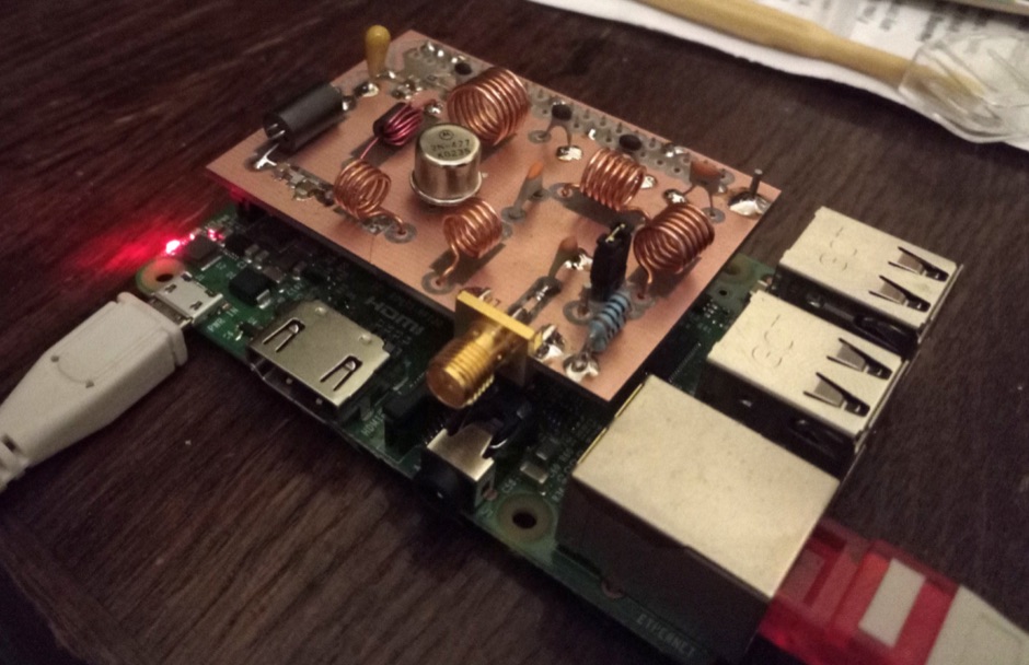 How to limit unwanted harmonics from your raspberry Pi radio transmitter by introducing filters.
 -
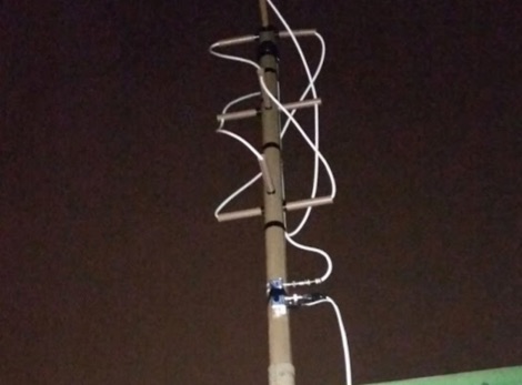 How to receive NOAA weather satellite with a home made QFH Antenna. This project includes some easy and efficient notch filters to suppress noise from FM frequencies
 -
 The **Yaesu FRG-100** shortwave receiver, introduced in 1992, operates across a frequency range of 50 kHz to 30 MHz, accommodating AM, LSB, USB, and CW modes, with an optional narrow-band FM capability. Its physical dimensions are 238 x 93 x 243 mm, with a weight of 3 kg, making it suitable for both portable and fixed station deployments. Power options include standard mains voltage or 12VDC, providing operational flexibility for diverse listening environments. The front panel integrates a manual tuning knob, an analogue signal strength meter, and an LCD display that provides critical information such as frequency, operating mode, memory channel, and time. Users can configure various operational parameters, including tuning steps and bandwidth filters, to optimize reception for specific signals. This review highlights the FRG-100's straightforward interface and its utility for shortwave listening enthusiasts. The design emphasizes user-friendly adjustments for settings, which contributes to its appeal among those interested in general coverage reception.