Search results
Query: frequency antenna
Links: 225 | Categories: 5
-
 Design your VHF UHF Yagi antenna online, a JavaScript enhanced web page that implements the design of an antenna for 2m and 70cm bands. This page offers a streamlined experience for Yagi antenna design enthusiasts. It assumes prior knowledge of Yagi design principles, minimizing distractions with a user-friendly interface. Equipped with essential equations, it provides instant design feedback. Red font warnings indicate design limitations, ensuring practical results. Constraints include Gain (11.8-21.6 dBd) and Boom Length (2.2-39 wavelengths), with additional frequency-dependent restrictions noted in input fields.
 -
 The G5RV antenna, with an overall length of **31.10m (102ft)**, functions as a 3/2-wave on 20 meters when installed horizontally at 12m (39ft), exhibiting a resonant frequency of 14.150MHz and an approximate resistance of 80 ohms. Its 10.36m (34ft) stub line, designed as a 1/2-wave on 14.150MHz with a 0.97 velocity coefficient, acts as an impedance transformer across other bands, aiming for multiband operation without traps. On 20m and higher frequencies, the G5RV demonstrates improved gain compared to a standard dipole, attributed to the _collinear effect_ from multiple 1/2-waves along the wire. The original design sought a multiband solution for limited spaces, often requiring an Antenna Tuning Unit (ATU) for effective operation across bands like 80, 40, 30, and 20m, particularly with modern solid-state PAs. Variants, such as the F8CI modification, incorporate a 1/4 current balun at the stub line's base for symmetrical-to-asymmetrical transition, known as a _remote balun_. Proper flat-top or inverted-V installation is critical for maintaining symmetry and collinear gain, with inverted-V apex angles below 120° progressively diminishing higher-band performance.
 -
 This guide provides step-by-step instructions for constructing a tin can waveguide antenna, commonly known as a cantenna, for enhancing WiFi signal range. The project is budget-friendly, costing under $5, and utilizes easily accessible materials like a food can and basic electronic components. The design is suitable for 802.11b and 802.11g wireless networks, operating within the 2.4 GHz frequency range. To start, gather the necessary parts including an N-Female chassis mount connector, nuts, bolts, and a suitable can. The assembly process involves drilling holes in the can for the connector and mounting the probe. The guide emphasizes the importance of can dimensions and placement for optimal performance, encouraging experimentation for best results. This project is ideal for amateur radio operators and DIY enthusiasts looking to improve their wireless connectivity without significant investment. Safety precautions are advised, as the author does not hold electrical engineering credentials. Users are encouraged to take responsibility for their equipment and ensure proper assembly. With this simple yet effective antenna, users can extend their WiFi coverage and enjoy enhanced connectivity.
 -
 The 4-band Fritzel model FD4 is a special version of a Windom antenna. It is a half-wave long on the lowest frequency, and is fed from a coax cable through a transformer inserted in the wire at one-third from one end
 -
 Enter the operating frequency and calculate dimensions of your jpole antenna
 -
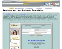 This basic calculator is designed to give the aproximate length (height) of a particular vertical antenna, for the frequency and wavelength chosen.
 -
 Details the construction of a J-vertical antenna specifically for the 10-meter band, offering a practical alternative to a _Slim Jim_ design for 28 MHz. The resource outlines the use of aluminum tubing for the half-wave vertical section and coaxial cable for the quarter-wave matching section, providing specific calculations for element lengths based on frequency and coaxial cable velocity factor. It contrasts the performance of the J-vertical with center-fed dipoles and end-fed verticals, noting superior results in previous comparisons. The article further presents a more recent iteration of the J-vertical, constructed using a fiberglass pole and insulated wire, with updated dimensions for 28.8 MHz. It includes practical advice on weatherproofing connections and securing the antenna for durability against adverse conditions, referencing the survival of an original _J Vertical_ during 110 MPH winds in 1987. The SWR performance is reported as 1.1:1 at 28.6 MHz, maintaining below 1.5:1 across 28.3 to 29 MHz.
 -
 Monitoring shortwave broadcast stations effectively requires accurate schedule information to identify transmissions. This online utility offers a straightforward, graphical interface designed to search for and display current shortwave radio broadcasting schedules. Users can precisely filter results by frequency, specific language, broadcaster, time of day, and even by shortwave band, which simplifies the process of pinpointing desired content. The database, last updated on March 26, 2023, details station callsigns (e.g., BBC), start and end times in UTC, days of the week, broadcast language, transmitter power in kilowatts, and azimuth. Crucially, it includes the precise geographical coordinates of transmitter sites, such as Woofferton in the UK or Al Seela in Oman. This data is invaluable for predicting signal paths and optimizing antenna direction for improved reception, a key consideration for serious SWLs. For instance, a search for BBC English broadcasts at 21:04 GMT quickly reveals multiple active frequencies like 17780 kHz from Woofferton, offering a clear overview of current transmissions. The tool processes queries rapidly, returning results within seconds, demonstrating its efficiency for broadcast listening enthusiasts seeking timely information.
 -
 The RXO Unitenna, a vertical wideband antenna, offers operation across the 7-21 MHz spectrum, covering the 40, 30, 20, 17, and 15-meter amateur bands. This design focuses on achieving a low SWR across a broad frequency range, making it suitable for general HF operation without requiring an external antenna tuner for minor SWR variations. The antenna utilizes a unique loading coil and matching network to maintain efficient radiation characteristics across its operational bandwidth. Construction details within the PDF document include specific dimensions for the radiating element and the counterpoise system, which is critical for vertical antenna performance. The design incorporates readily available materials, simplifying the build process for radio amateurs. Performance graphs illustrate the SWR characteristics across the 7 MHz to 21 MHz range, demonstrating the antenna's wideband capabilities. The document also provides guidance on feedline connection and grounding considerations for optimal field deployment. This vertical antenna configuration is particularly useful for hams with limited space, offering a compact footprint compared to horizontal wire antennas.
 -
 Determining the actual need for an antenna tuner often hinges on the specific antenna and feed line configuration in use. While many hams believe a tuner is always essential, its primary role is to present a 50-ohm impedance to the transceiver, not to "tune" the antenna itself. For instance, a resonant dipole fed with _coaxial cable_ at its design frequency typically requires no tuner, as the feed line impedance closely matches the radio's output. However, operating a non-resonant antenna, or using a resonant antenna on multiple bands, frequently necessitates a tuner to manage high Standing Wave Ratio (SWR) on the feed line. The article clarifies that a tuner placed at the transceiver only matches the radio to the feed line, not the antenna to the feed line. For maximum efficiency with a non-resonant antenna, an _automatic antenna tuner_ (ATU) or a remote tuner placed at the antenna feed point is often more effective, minimizing losses in the feed line. The discussion also touches on the practical implications of SWR, noting that modern transceivers often fold back power at high SWR, making a tuner a practical necessity to achieve full output power, even if the antenna itself is not perfectly matched.
 -
 Enter the resonant frequency for the dipole/vee antenna calculation
 -
 Calculates resonant frequency of a loop antenna, correcting for distributed capacitance.
 -
 Over 30 distinct shortwave (SW) receiver models are reviewed, offering insights into their performance, features, and user experiences. These evaluations, contributed by readers of the Usenet newsgroup **Rec.radio.shortwave**, cover a wide array of portable and tabletop radios, including popular units like the Grundig YB-400, Sony ICF-SW77, and various Realistic DX series models. Each review details aspects such as frequency range, tuning steps, SSB functionality, antenna performance, and construction quality, often comparing them to other receivers or ham transceivers like the Icom 725. For instance, the Grundig YB-400 review highlights its 144-30000 kHz AM/SSB coverage, direct keypad entry, and 40 station memories, noting its useful narrow bandwidth and tone switch for adjacent signal separation. It also discusses the **SSB mode** stability and the limitations of its 1 kHz frequency resolution for precise zero-beating. The review further details antenna performance, including the effectiveness of the built-in whip, the provided 7m reel antenna, and the potential for overload with larger outdoor antennas. Other reviews delve into specific issues, such as the Sony ICF-SW77's frequency display inaccuracies and timer malfunctions, or the Realistic DX-342's compact size and surprisingly good MW DXing capabilities despite its analog tuning. The collection provides practical, user-generated feedback on sensitivity, selectivity, audio quality, and ergonomic features, helping shortwave listeners understand the real-world performance and quirks of these receivers.
 -
 Antenna for GSM, CB, marine, VHF/UHF, HAM and high frequency 1,9/2,4GHz
 -
 This antenna modification is for the IEEE 802.11b networking protocol that operates at 2.4 GHz. It can be scaled easily to the 5 GHz frequency used by IEEE 802.11a by simply scaling the dimensions on the feed can and the excitation antenna to 2.4/5 = 48% of the dimensions shown above.
 -
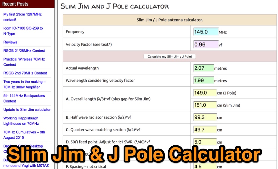 How to make a simple but effective Slim Jim antenna. It includes a calculator to work out all the mesurements for the frequency you require.
 -
 manufactures and distributes HF, VHF, UHF and SHF equipment covering 10MHz. - 47.0GHz. Our products include: Wireless LAN / WAN Bidirectional Linear Amplifiers, Low Noise Preamplifiers - LNA's, RF Linear Amplifiers, Relays, Transverter Systems, Frequency Translation Systems, Downconverters, Antennas, Parabolic Dishes, Coaxial Cable, Relays, Antenna Switches, Microwave Test equipment, PC controlled Receivers, Microwave Linear Amplifiers including models for Telemetry, Wireless, and CDMA applications.
 -
 Selecting an appropriate antenna system for shortwave broadcasting involves evaluating various types based on performance, cost, and operational parameters. This resource details the critical specifications for broadcast antennas, including average and peak power ratings, directivity, takeoff angle (TOA), horizontal beamwidth, and gain, emphasizing that a 100-kW transmitter requires an antenna rated for 150 kW average and 400 kW peak. It clarifies that low TOA signals travel thousands of kilometers, while high TOA is for local coverage, and nearly all modern shortwave broadcast antennas are horizontally polarized. The article explores specific antenna types, such as Log-Periodic Antennas (LPAs), which offer wide frequency ranges (e.g., 2-30 MHz) and directional patterns with 11 dBi gain, costing from $20K to over $100K for multi-curtain versions. Dipole arrays, also known as curtain antennas, are prevalent in international broadcasting, featuring steerable beams (±15° and ±30°) and mode-switching capabilities to alter TOA, with high/low pairs costing over $1 million. Fan dipoles are noted for omnidirectional patterns, smaller size, and lower cost for low-power applications, while rhombics, though simple, require resistive termination and incur several dB of I2R losses. Balun considerations are crucial, as most communications baluns are not rated for the higher average and peak powers of AM broadcast transmitters. Modern shortwave antennas utilize durable materials like Alumoweld wire rope for radiators and support elements, avoiding copper, fiberglass, or materials prone to stretching or deterioration. Feeder systems for high-power stations often require tapered-line baluns to convert 50-ohm unbalanced power to 300-ohm balanced for connection to the antenna.
 -
 This article addresses the subject of obtaining the best signal transfer from an antenna to the typical 50-ohm receiver input over a wide frequency range, with emphasis on medium-wave (500 - 2000 kHz), encompassing the standard AM broadcast band and the 160-m amateur band.
 -
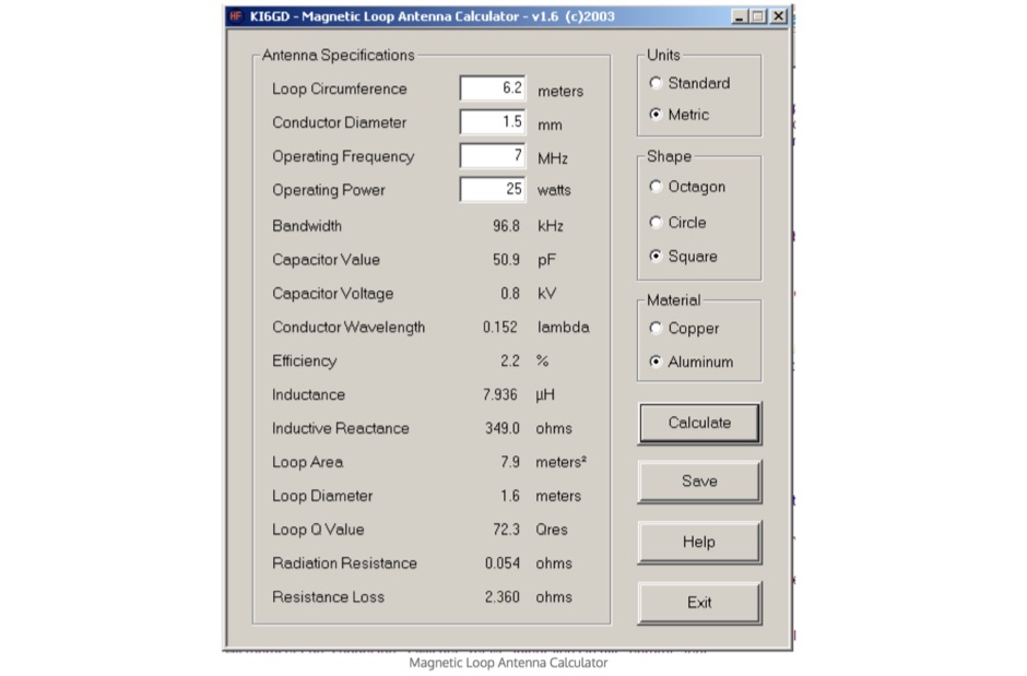 Free windows program to calculate magnetic loop antenna.This small loop antenna calculator allow to determine capacitance and voltage based on Loop circumference, desired resonant frequency, conductor diameter and the operating power
 -
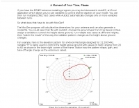
 What is NVIS Near Vertical Incident Skywave. This article on NVIS (Near Vertical Incidence Skywave) explores its role in short-range HF communication, covering 0-200 miles. NVIS utilizes antennas with high radiation angles and frequencies below the ionospheric critical frequency to achieve reliable local contact. He details optimal antennas, like low dipoles, and practical tips for maximizing NVIS performance, emphasizing its advantages such as reduced noise and independent operation without repeaters. However, challenges include frequency sensitivity and the need for appropriate antenna setups at both ends for effective communication.
 -
 The **NW3Z** optimized wideband antenna designs, originally presented at Dayton 2001, detail Yagi configurations for the 20-meter, 15-meter, and 10-meter amateur radio bands. This resource provides access to the design files, likely containing critical parameters such as element spacing, element lengths, and boom dimensions, which are essential for replicating these directional antennas. The designs focus on achieving wide bandwidth, a desirable characteristic for contesters and DXers operating across a significant portion of each band. The content specifically references "nw3z-Antenna-DesignsDownload," indicating that the core information is available as a downloadable file, presumably in a format suitable for antenna modeling software or direct construction. Such files typically include **NEC models** or similar data, allowing for performance analysis and optimization before physical construction. The emphasis on "optimized wideband" suggests design considerations for SWR bandwidth and gain characteristics over a broader frequency range than typical narrow-band Yagis. The resource serves as a direct source for specific, proven antenna designs from a known amateur radio antenna designer, offering practical data for hams interested in building high-performance Yagi arrays for HF.
 -
 Radio Scanners Uniden Bearcat, Antennas, CB_Radios, Ni-Cad Batteries, Frequency Books, Accessories, Power Supplies and Cords, FM Two Way Radios, and other Related Merchandise
 -
 MoxGen will show you the dimensions and generate an antenna model file for a 50 ohm Moxon Rectangle antenna, given the design frequency and wire size
 -
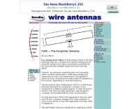 The terminated tilted, folded dipole T2FD is a little known antenna that performs excellently. Compact in size compared to a half-wave dipole the T2FD provides signal gain, wide frequency coverage, and exceptionally low noise characteristics.
 -
 These devices are called Traps, but they are actually more like frequency sensitive switches. They are parallel resonant, high Q, tuned circuits which provide a very high impedance at their frequency of resonance.
 -
 Professional antennas in MF, VHF, UHF and SHF frequency range for military applications, civil-professional market, mobile communications, radioamateurs and antennas for special applications - EMC, radiomonitoring, etc.
 -
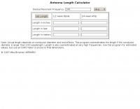 Input the desired resonant frequency and it will calculate lenght in inches feet and meters
 -
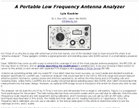 A Portable Low Frequency Antenna Analyzer, For those of us who like to play with antennas on the ham bands, one of the handiest tools to have around the shack is an "antenna analyzer". These gadgets combine a signal generator and standing-wave ratio (SWR) sensor in a small battery-powered unit.
 -
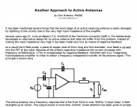 Active antenna with a frequency response that is flat from 5kHz to over 30MHz
 -
 Constructing an HF End-Fed Half-Wave (EFHW) vertical antenna, the resource details the winding of a monoband matching unit, inspired by _AA5TB_, designed to provide a 50 Ohm impedance match without a ground plane or antenna tuner. It specifies the use of a _T200-2_ ferrite core for the transformer, outlining the 13-turn secondary and 2-turn primary winding process with enamelled copper wire. The document also describes the integration of a coax capacitor, whose length is critical for tuning and varies by band, with specific starting lengths provided for 20m, 17m, 15m, 12m, and 10m operation. The practical application section guides the builder through tuning the antenna using an antenna analyzer, emphasizing the iterative process of spacing secondary windings and trimming the coax capacitor to achieve resonance at the desired band frequency. It highlights the antenna's low angle of radiation, beneficial for DX, and claims up to 2 S-points improvement over a _G5RV_ or similar doublet when used as an omnidirectional vertical. A comprehensive shopping list, including specific part numbers from _Rapid Electronics_, is provided, along with advice on selecting fiberglass fishing poles for support and suitable antenna wire.
 -
 Over 75 years of engineering expertise underpins Bird Electronic's offerings in RF power measurement, critical for maintaining peak performance in amateur radio stations and professional communication systems. The company specializes in a range of test equipment, including wattmeters, SWR meters, and antenna analyzers, essential for optimizing antenna systems and ensuring efficient power transfer. Their product line extends to various RF components such as filters, cables, and connectors, all designed to meet stringent technical specifications for reliability and accuracy across diverse frequency bands. Bird Electronic's instruments, like the _Bird 43_ Thruline Wattmeter, are widely recognized for their robust construction and precise measurement capabilities, providing hams with confidence in their station's operational parameters. These tools enable accurate assessment of forward and reflected power, SWR, and modulation characteristics, which are vital for troubleshooting and maximizing radiated power. The company's commitment to innovation ensures that its products remain relevant for modern RF challenges, from HF through microwave applications, supporting both traditional analog and advanced digital modes.
 -
 Details a practical QRP wattmeter construction, leveraging a simplified SWR meter design by JA6HIC. The project focuses on a forward-only power measurement circuit, providing a functional instrument for RF power levels from milliwatts up to 5 watts. It maintains a 50-ohm input and output impedance, suitable for typical QRP transceivers and antenna systems. The resource includes the schematic for the "VSW" (Very Simple Wattmeter) and outlines a six-step alignment procedure. This calibration process involves using a known RF source up to 5W, setting full-scale deflection, and marking power increments. It also addresses minimizing frequency effects on readings with a 100pF trimmer capacitor, noting that measurement error is highest at the lower end of the scale. Construction notes mention using a piece of RG-213 coaxial cable for the inductance and coupler, with the wattmeter assembled in early 2003. The author provides an example measurement showing 0.8W into a dummy load and 1W into a 3-element beam.
 -
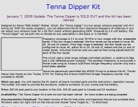 The "Tenna Dipper" is a low power antenna analyzer and ATU tuning aid. With this handy accessory, you can determine the 50 Ohm resonance frequency of antennas or you can adjust your antenna tuner for a 50 Ohm match without generating QRM
 -
 This PDF document, authored by KT4QW in October 2004, details the construction and modeling of a dual-band, horizontally polarized hanging rectangular loop antenna for **10 and 17 meters**. The design, adapted from *The ARRL Handbook*, utilizes _NEC4WIN95_ software for scaling and optimization, targeting a 50 ohm feedpoint impedance. The resource includes a bill of materials, step-by-step construction instructions, and a discussion of the antenna's radiation characteristics. It presents NEC-generated elevation and azimuth patterns, comparing the loop's performance to a half-wave horizontal dipole at the same height and frequency. The 17-meter element is centered at 18.140 MHz for low SWR across the phone band, while the 10-meter element is centered at 28.500 MHz. Construction involves 14-gauge stranded copper wire and Schedule 40 PVC spreaders, with the total wire length calculated by the formula: Length in feet = 1005/MHz. The feedpoint impedance can be adjusted by modifying the rectangular aspect ratio. The document specifies hoisting the antenna to at least a half-wave above ground for testing. It notes that a balun was tested and found to have no measurable effect on SWR or radiation characteristics. A 2-meter scale model is presented to illustrate the physical design, and a "rotator" string is incorporated for directional adjustment up to 90 degrees.
 -
 WorldRadio Article on Petlowany antennas base on this principle: if a length of wire is wound into a spiral-shaped coil and excited by a radio frequency current connected to the innermost portion of the coil, it will then, and only then, exhibit RF characteristics that closely approximate those of a resonant linear wire of the same length
 -
 This is a resonant, half-wave, vertical antenna. It takes up little space in the back yard, was designed for operation on a single frequency 80 meter PSK net, and is reasonably inexpensive to construct by Chuck Hines, K6QKL
 -
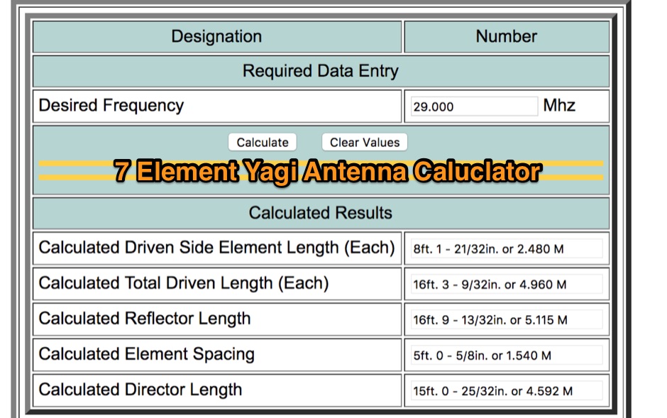 Online javascript antenna calculator designed to give the critical information of a particular beam antenna, in this case a seven element Yagi, for the frequency chosen.
 -
 VX-5R Loose antenna cure, Vx-5r Free Band, VX 5 R modification for German, VX-5R expanded frequency mod, VX-5R MARS/CAP & freeband mod
 -
 A javascipt online calculator for 2 and 3 element beam antennas. Just input frequency and will diplay element dimensions and spacing. Measurements in Feet and Meters by G4VWL
 -
 Online Moxon antenna calculator. Design your moxon antenna online giving wire diameter and resonant frequency
 -
 An experimental antenna similar to the TAK spiral antenna was evaluated for SWR response over the frequency range of 7.0 to 7.3 MHz, or the 40-meter band.
 -
 Theory, Modeling, and Practical Applications By W5JCK, presentation in PDF File. This presentation focuses on Near-Vertical Incidence Skywave (NVIS) antennas, which are crucial for short-range radio communications, particularly in military and emergency contexts. It explores NVIS theory, antenna models, and installation criteria while debunking common myths about reflectors. Key topics include usable frequency bands, optimal installation heights, and the impact of soil quality on performance. The presentation outlines the best bands for daytime and nighttime use, emphasizing the importance of understanding propagation characteristics to enhance communication effectiveness within 200 to 300 miles.
 -
 Manufacturer of Fibreglass Whip Antennas, Low and mediun Frequency, HF and VHF Antennas Specialized in the design and manufacturing of a full range of Beacon (MF), AM Broadcasting 540 - 1700 KHz, HF 1.7 to 30 MHz, VHF 30 to 156 MHz and UHF 200 to 500 MHz antennas.
 -
 The article "Exploring the World of 10 Meter Beacons" by Ken Reitz, KS4ZR, provides an in-depth look at 10-meter beacon operations, focusing on their utility for propagation analysis. It details FCC Rules part 97.203 governing beacon stations, including license requirements, power limits (under 100 watts), and the specified band segment of 28.200-28.300 MHz for U.S. operations. The content highlights the diversity in beacon construction, from converted CB radios to home-brew QRP transmitters, and discusses the robust operating conditions these 24/7 stations endure. The resource presents several case studies of active 10-meter beacon operators like Ron Anderson KA0PSE/B, Domenic Bianco KC9GNK/B, and Bill Hays WJ5O/B, detailing their equipment, antenna setups, and typical signal report volumes. It also introduces the NCDXF/IARU International Beacon Project, which features 18 synchronized beacons worldwide transmitting on 28.200 MHz at varying power levels (100W, 10W, 1W, 100mW) to facilitate propagation testing. The article also covers the PropNet Project utilizing PSK31 on 28.131 MHz and the 250 Synchronized Propagation Beacon Project on 28.250 MHz. Practical advice for monitoring includes using the RST reporting method, understanding the impact of the solar cycle on 10-meter propagation, and tips for setting up a personal beacon, such as frequency selection and power output considerations. The IY4M Guglielmo Marconi Memorial Beacon Robot on 28.195 MHz is also mentioned for its automatic QSO mode. The article concludes with a list of other resources for 10-meter beacon information.
 -
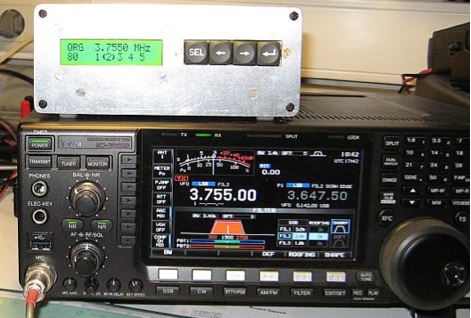 This Arduino project decode ICOM CAT frequency information and switch antennas according to preset values. RX and TX antennas can even be different, a project by ON7EQ
 -
 Constructing a compact, two-band magnetic loop antenna for HF operation, especially from constrained locations like a balcony, presents unique challenges. OK1FOU's design, inspired by DJ3RW's 50 MHz loop, addresses these by employing an unusual side-fed configuration and placing the symmetric, two-section variable tuning capacitor at the bottom of the loop, directly connected to the coax shield. The article provides specific material recommendations, including two 1-meter wooden pales and about 3 meters of thick loudspeaker cable, noting the high current (60A at 100W) in the loop. Construction steps detail forming two turns with a 5 cm gap, using a GDO to pre-tune the open loop to a frequency slightly above the desired highest band, and then integrating the tuning and coupling capacitors. For 10/14 MHz, an open loop resonance of 16-17 MHz is suggested. Practical experience with the 10 MHz band from a third-floor balcony in Prague (JO70GC) shows a 1:1 SWR across most of the band without an external ATU. While DX traffic was modest due to the urban environment, QSO examples with RA6WF, LA6GIA, G0NXA, and LZ1QK on 10 MHz are provided, demonstrating its operational capability.
 -
 Constructing a Lindenblad antenna for 137MHz NOAA satellite reception involves specific design considerations for optimal performance. The resource details the use of 4mm galvanised steel fencing wire, 300-ohm television ribbon cable, and wood/plastic components for the antenna structure. Key dimensions for a 137.58MHz-resonant antenna are provided, derived from the ARRL Satellite Handbook, specifying s, l, w, and d as 42, 926, 893, and 654mm respectively. The antenna is designed for Right Hand Circularly Polarised (RHCP) signals, requiring the four folded dipole elements to be tilted clockwise by 30 degrees. A significant aspect covered is impedance matching between the antenna's 75-ohm impedance and a typical 50-ohm receiver input. A twelfth-wave matching transformer, constructed from 117mm sections of 50-ohm RG-58 and 75-ohm RG-59 coax with a 0.66 velocity factor, is described. The article also addresses coaxial cable and connector selection, recommending 75-ohm Type-N connectors for RG-6 cable in professional setups and F56/F59 connectors for general use, while strongly advising against PL-259/SO-259 connectors for VHF. Strategies for mitigating Radio Frequency Interference (RFI) are discussed, including antenna placement to shield from local TV transmitters and the use of commercial or DIY band-pass filters, such as cavity resonators or helical notch filters, along with ferrite chokes on coaxial cables. Antenna orientation is explored, noting the Lindenblad's 'cone of silence' directly overhead and its maximized sensitivity towards the horizon. An experimental vertical tilt of 90 degrees is presented as a method to improve overhead reception and reduce interference from strong horizontal signals, particularly relevant in high RFI environments like the Siding Spring Observatory site.
 -
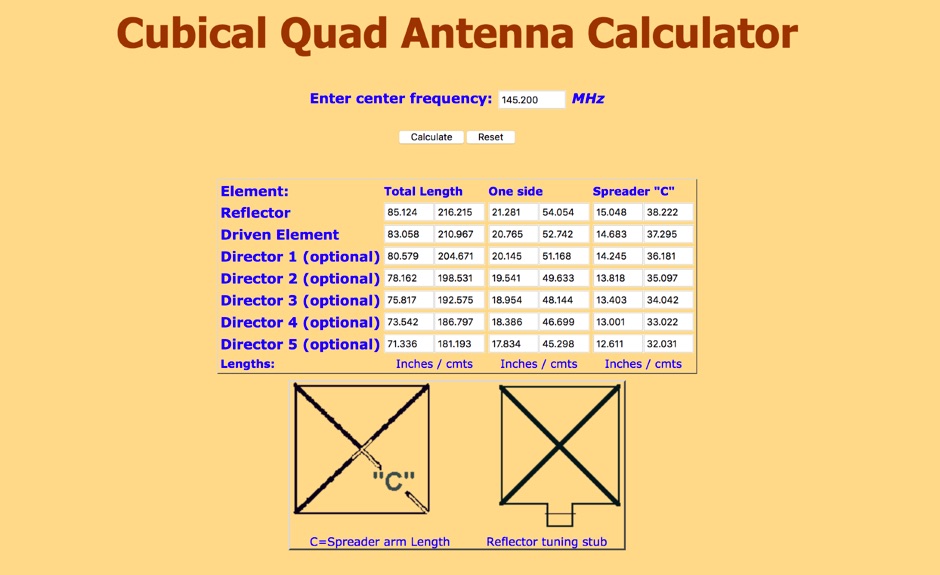 Easy Quad calculator, enter center frequency to get a quad antenna size
 -
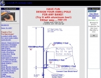
 Design your owm HF shiortened dipole. Includes a diagram of a lumped-constant loaded dipole antenna that is intended to fit in available space, rather than requiring a full 1/2 wavelength, at a specified frequency