Search results
Query: ft meter
Links: 260 | Categories: 4
-
 Audio Spectrum Analyzer for Real-time, FFT, OscilloScope, Frequency counter, voltmeter, noise and distortion meter, phase shift meter. Multi-Tone Sound Frequency Sweep Generator. White, pink noise.
 -
 A 10-20 meters coverage delta loop antenna. After relocating, DL2HCB designed a multiband loop antenna to cover 10-20m with an open-wire feed for impedance matching and compact installation. Inspired by the mini-X-Q design, a modified 10m delta-loop was built, enhanced with a 1/4 wave shorted stub for 28 MHz using 450-ohm ladder line. The antenna delivers east-west broadside radiation and performs as a closed loop on other bands. Operational tests yielded strong European signals and successful DX contacts, including a 20m QRP QSO with FY/DJ0PJ.
 -
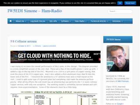
 The G5RV antenna, with an overall length of **31.10m (102ft)**, functions as a 3/2-wave on 20 meters when installed horizontally at 12m (39ft), exhibiting a resonant frequency of 14.150MHz and an approximate resistance of 80 ohms. Its 10.36m (34ft) stub line, designed as a 1/2-wave on 14.150MHz with a 0.97 velocity coefficient, acts as an impedance transformer across other bands, aiming for multiband operation without traps. On 20m and higher frequencies, the G5RV demonstrates improved gain compared to a standard dipole, attributed to the _collinear effect_ from multiple 1/2-waves along the wire. The original design sought a multiband solution for limited spaces, often requiring an Antenna Tuning Unit (ATU) for effective operation across bands like 80, 40, 30, and 20m, particularly with modern solid-state PAs. Variants, such as the F8CI modification, incorporate a 1/4 current balun at the stub line's base for symmetrical-to-asymmetrical transition, known as a _remote balun_. Proper flat-top or inverted-V installation is critical for maintaining symmetry and collinear gain, with inverted-V apex angles below 120° progressively diminishing higher-band performance.
 -
 The Super Loop Antenna page, designed by Jim W4FTU, provides detailed information on the RadioWorks \'Superloop III\' antenna as an alternative for operators with limited space. The page discusses the physical variations of the antenna, including dimensions and materials used, as well as its electrical characteristics such as the 30\' ladder line. The content is useful for amateur radio operators looking for antenna options for the 80 and 40 meter bands, especially those with small lots or zoning restrictions. The page is well-organized and informative, making it a valuable resource for antenna enthusiasts.
 -
 The **Extended Double Zepp** (EDZ) antenna, a simple wire design, is presented as a means to achieve 3-4 dB of gain on 10 meters, with an overall length of just 43 feet. This resource, authored by WB3HUZ, details several gain antennas suitable for the 29 MHz AM segment, all modeled using EZNEC software at 30 feet above ground. Other designs include a compact rectangular loop, offering more gain than the EDZ and a lower take-off angle, and the **Lazy H**, a bidirectional antenna providing 6 dB gain, which is also workable on 20, 17, 15, and 12 meters. The Bisquare, a diamond-shaped open-top loop, is also featured, providing approximately 4 dB gain and requiring only a single support. These designs are primarily fed with ladder line or open-wire line to simplify matching, though a coax feed option for the EDZ is shown for 10-meter-only operation. The Lazy H, for instance, requires about 16 feet of open-wire line for its half-wavelength elements spaced a half-wavelength apart. An enhanced EDZ Lazy H variant is also discussed, achieving an additional 1-2 dB gain by extending element length to 1.28 wavelengths and increasing spacing to 0.64-0.75 wavelengths. The Bisquare, while primarily a 10-meter antenna, can be adapted for 20 meters by closing the top connection.
 -
 This PDF article from April 2001 QST details the construction of the "NJQRP Squirt," a reduced-size 80-meter inverted-V dipole antenna. The resource provides a general construction sketch, a photograph of the assembled antenna, and specific dimensions for PC-board insulators. The antenna consists of two wire legs, each approximately **34 feet long**, separated by 90 degrees, fed at the center. It is designed for operation on 80 meters (3.5-4.0 MHz) as a quarter-wavelength antenna, requiring a low-loss feedline and an external antenna tuner due to its non-resonant feedpoint impedance. Construction utilizes readily available materials, including 1/16-inch glass-epoxy PC board for end and center insulators, and #20 or #22 insulated hookup wire for the elements. The feedline specified is 300-ohm TV flat ribbon line, with a note on potential trimming for tuner compatibility. N2CX reports the antenna's center should be elevated to at least **20 feet**, with ends no lower than seven feet above ground, resulting in a ground footprint of approximately 50 feet wide. The design prioritizes NVIS propagation for local 80-meter contacts. DXZone Focus: PDF Article | 80m Inverted-V Dipole | Construction Notes | 34 ft element length
 -
 For radio amateurs considering homebrew antenna projects, this resource details several designs from WE6W, an experienced operator. It covers the construction and characteristics of a _160 Meter QRP Loop Antenna_ optimized for high voltage, along with standard and folded variations of the double bazooka antenna. The site also presents a unique Field Day antenna design and instructions for building a Sterba Curtain, a directional array known for its gain. Each design includes practical insights from the author's building experience. The author provides comparative data, such as the performance of a standard bazooka against a traditional dipole, offering real-world context for antenna selection. The Sterba Curtain section includes notes on its beamwidth and gain, crucial parameters for directional operation. These designs are suitable for hams looking to experiment with cost-effective, high-performance antennas for various bands and operating scenarios, from QRP on 160m to directional DXing with a Sterba Curtain, which can offer significant forward gain, often exceeding **10 dB**.
 -
 Amateur radio operators often seek reliable equipment for various modes and bands, from QRP operations to high-power DXing. Historically, Ten-Tec has been a notable manufacturer in the amateur radio market, known for its range of products including HF and VHF transceivers, RF amplifiers, and antenna analyzers. Their product line also encompassed specialized items such as QRP transceivers and kits, catering to enthusiasts of low-power communication, and antenna tuners for impedance matching. The company's offerings included test equipment vital for shack setup and maintenance, like SWR meters and RF analyzers, which assist in optimizing antenna systems and ensuring efficient power transfer. Additionally, Ten-Tec provided various accessories and components, supporting both commercial products and homebrew projects. The brand was recognized for its _made in the USA_ manufacturing, appealing to operators who prioritize domestic production. While the website currently displays limited product information, it mentions upcoming items like the _MODEL 594 PHOENIX_ and the _Tune-A-Tenna_, indicating potential future product releases.
 -
 This resource provides access to the 59+ software collection, specifically highlighting the **59+ CW** module. The software enables the generation of Morse code signals for transmission through a COM port to a transceiver, or for audio output via a computer speaker, facilitating both keying and listening practice. Users can customize various parameters, including CW speed, tone frequency, dash/dot ratios, and PTT line delay, alongside defining keyboard shortcuts for common QSO fields such as callsign, QTH, name, and RST. The collection also includes the 59+ Logbook, which operates smoothly on Windows XP according to testing notes, though the CW application experienced startup issues on the same OS. The software was originally designed for older Windows operating systems, specifically Windows 95, 98, ME, and 2000. It is noted that the original idealog.net site is no longer active, and development for the 59+ suite appears to be discontinued. Analyzer and converter modules within the collection require registration and do not function in trial mode.
 -
 The project details a DIY SWR/Wattmeter designed around an _Arduino Uno_ shield, providing capabilities to measure RF power from 2 to **200 watts** and Standing Wave Ratio (SWR) for HF amateur radio bands. This construction features a compact design, integrating the measurement circuitry directly onto a custom PCB that interfaces with the Arduino Uno microcontroller. Key components include a directional coupler for sensing forward and reflected power, precision rectifiers, and analog-to-digital conversion for processing RF signals. The Arduino firmware handles calibration, calculations, and displays the results on an integrated LCD, offering real-time feedback on antenna system performance. The design prioritizes simplicity for homebrewers. Performance specifications indicate accurate readings within the **2-200W** power range, suitable for typical QRP to medium-power HF operations. The project provides schematics and a basic overview of the software logic.
 -
 Oscilloscope, Realtime spectrum analyzer, Impedance meter, RLC bridge and signal generator for Windows. Is a Windows application that converts your PC into a powerful dual-trace signal analyzer (oscilloscope, FFT etc...) . Uses your PC sound card as an Analog-to-Digital a Converter to digitize any input waveform and as Digital-to-analog Converter for the signal generator. True 24 bit adc/dac 48K/96k/192k sampes/sec.
 -
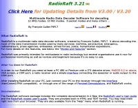 RadioRaft decodes 10 different ARQ modes, 8 different FEC modes, Packet, Baudot, CW... It works with a Hamcomm interface or a radiomodem. RadioRaft offers automatic detection of modes, speeds and shift. It comes with a frequencymeter/baudmeter included, it has signal frequency tracking and a bit by bit display mode. Very easy to use. practical and fast.
 -
 Presents a practical design for a **crossed-dipole turnstile antenna** specifically engineered for 2-meter Amateur Radio Direction Finding (ARDF) events. The author, WB6RDV, details a robust, omnidirectional, horizontally-polarized antenna, addressing the international ARDF rules requiring such characteristics at a height of two to three meters above ground. This contrasts with the vertical polarization often used in Southern California, highlighting the design's adherence to specific event requirements. The electrical design employs a classic crossed-dipole with a 75-ohm phasing section, resulting in a slight impedance mismatch and an SWR of approximately 1.3:1 with a 50-ohm feedline. Construction utilizes readily available and inexpensive PVC plumbing components and 1/8-inch bronze welding rod for elements. The guide provides step-by-step instructions for mechanical assembly, including drilling element holes at precise 90-degree spacing and preparing the RG-179 matching section. WB6RDV shares insights from his own build experience, discussing the use of plated brass versus aluminum spacers for element attachment and the effectiveness of crimping as an alternative to soldering. The document also covers final assembly, including the integration of ferrite beads as a choke balun and options for weatherproofing and alternative mounting configurations, emphasizing the adaptability of the design for other VHF bands through scaling.
 -
 Operating on the HF bands, Kenwood's TS-990S and TS-890S transceivers represent their flagship offerings, providing advanced features for DXing and contesting. My personal experience with Kenwood gear, particularly the TS-590SG, confirms their reputation for solid receive performance and clean transmit audio, often noted in pileups. The TS-590SG, a popular choice for many hams, delivers reliable performance across the HF and 6-meter bands, making it a versatile station centerpiece. For VHF/UHF enthusiasts, the TH-D75A tribander offers 144, 220, and 430 MHz capabilities in a portable form factor. This handheld unit integrates D-STAR and APRS functionalities, appealing to operators who value digital modes and location-based services on the go. The inclusion of 220 MHz, a less common but valuable band, expands its utility for regional communications and specialized nets. Kenwood's enduring presence in the amateur radio market, dating back to 1955, underscores a commitment to quality and innovation. Their product range, from high-end base stations to feature-rich portables, continues to support a wide array of operating styles and technical requirements within the ham community.
 -
 The DSP-10 is an amateur-radio, software-defined 2-meter transceiver that can be built at home. It operates not only on SSB, FM and CW, but also on four Weak-Signal modes. Features are tailored to operation on VHF, UHF and Microwave frequencies. By W7PUA
 -
 Version 7.22 of XMLog provides a fix for an issue where the ARRL LoTW application TQSL produced error messages concerning invalid "MY-COUNTRY" values, ensuring smoother integration for award submissions. The software supports flexible log searching, allowing users to select log subsets based on any field, such as RTTY QSOs on 40 meters during a specific month, or entries for a single country with sent but unreceived QSLs. XMLog tracks DXCC, WAZ, WAS, county hunting, IOTA, and grid square awards, managing QSL sent/received status and submission status to award sponsors, with LoTW crediting for DXCC and WAS. It generates detailed reports summarizing QSL status by band and mode, identifying needed countries/states/zones, and listing critical QSOs that could boost award totals. The system also integrates with callbook services like QRZ.com (subscription required) and WM7D.net for lookups, and facilitates QSL and mailing label printing using standard or custom layouts. Further capabilities include ADIF, Excel, and CSV log import/export, a Packet Window for Internet PacketCluster nodes or TNCs with history and scripting, and vocal/CW alerts for needed QSOs based on PacketCluster spots. Rig control is supported for a wide array of Alinco, Elecraft, Flex, Heath, Icom, JRC, Kenwood, TenTec, and Yaesu transceivers, enabling frequency/mode synchronization and control. CW support is provided via a serial port interface compatible with N1MM or K1EL WinKeyer, allowing CW sending from a keyboard or pre-programmed messages.
 -
 We often think of the Moxon rectangle as strictly an HF antenna. However, its small size and special far field pattern lend themselves to some VHF applications. So let's see how to adapt the design to 2 meters (as a popular band choice) and also see a few of the uses to which we may effectively put the design.
 -
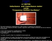 Inductance and Capacitance meter using``Frequency Shifted Oscillator
 -
 Eight-channel Audio Spectrum Analyzer is a set of Real-Time Multi-Channel Gauges for investigation of data accepted from any ADC you will want or 16-, 24- and 32-bit ADC of sound card. WDM drivers support. FFT Spectrum Analysis, OscilloScope, Frequency counter, AC/DC voltmeter, Signal-to-Noise Ratio, Signal-to-Noise and Distortion, Spurious-Free Dynamic Range, Effective Number Of Bits, Total Harmonic Distortion, Inter-Modulation Distortion, Phase Shift. Special modes of dual-channel FFT spectral analysis: Separate channels spectra, Spectra of digital sum, difference, product of two signals, Spectrum of digital product of original signal and its fundamental, Spectrum of Real and Complex Transfer Function, Cross Spectrum. Standart weighing of spectra according IEC and CCIR. Oscilloscope modes (for dual-channel ADC) are: original signals, sum, difference, dependence of one channel on another, amplitude distribution of input signals.
 -

-
 40 meters band Delta loop antenna plan that is vertically polarised
 -
 The project details modifications to an ARK-40 QRP CW transceiver kit, specifically replacing its original thumbwheel frequency selectors with a **BASIC STAMP BS-II microcontroller** and an optical shaft encoder. The redesigned control circuitry outputs a BCD code to the ARK-40's synthesizer, enabling more convenient knob-type tuning. This modification significantly alters the user interface, moving from discrete frequency selection to continuous tuning. Operating frequency is presented on an LCD readout, offering two distinct display modes: a "bandspread dial" mode that simulates an analog dial scrolling across the display in 1 kHz increments, and a conventional digital readout with 100 Hz resolution. Pushing the main tuning knob toggles between these modes, providing both rapid band traversal and fine-tuning capabilities. The software for the BASIC Stamp is written in P-Basic, addressing the challenge of accurate analog dial simulation. Physical modifications include fabricating a custom PC Board for the STAMP, mounting it with an L-bracket to the optical encoder, and creating a new front panel. The front-mounted speaker was relocated to accommodate the new tuning knob and display, transforming the **ARK-40 transceiver** into a more user-friendly rig with its built-in CW keyer and 5 watts of power.
 -
 The Bruce array is a simple, often-forgotten wire antenna array that is advantageous for 80 and 160 meters, where typical gain antennas are very large. This bi-directional broadside vertical array is only 1\4 lambda high and does not require a ground system. It offers substantially greater SWR bandwidth than the half-square or bobtail curtain. A 4-element Bruce array used by N6LF showed a gain of about 4.6 dB compared to a 1\4 lambda vertical with 8 elevated radials, with a 2:1 SWR bandwidth greater than 400 kHz. The antenna is simple and its dimensions are flexible.
 -
 Delta Loop Antenna for 15m band. This antenna is made for operating from outdoors, mainly from mobile shack. Drive to a parking you like, then build it up. Just half an hour later, you can enjoy slightly better gain than normal dipole.
 -
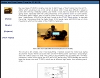 Meter and Low Power Tune for FT-857D
 -
 Manual for R7, 10 12 15 16 20 30 40 meters band antenna
 -
 Catalogs a diverse array of Software Defined Radio (SDR) projects and realizations, systematically classified by their sampling methodologies and underlying hardware architectures. The resource delineates projects into categories such as those utilizing soundcard sampling of traditional transceiver audio outputs (Type Ia), mono soundcard sampling of intermediate frequencies (Type R1x-x-xx), stereo soundcard sampling of I/Q IFs (Type Q1x-x-xx), dedicated stereo audio ADC sampling of I/Q IFs (Type Q2x-x-xx), direct antenna RF signal sampling with off-the-shelf acquisition boards (Type R3x-x-xx), dedicated RF ADC sampling of analog IFs (Type R2x-x-xx), dedicated RF ADC sampling of direct antenna RF signals with ASIC-based processing (Type R4x-A-xx), FPGA-based processing (Type R4x-F-xx), and specialized IF chipsets combining ADC and DDC functions (Type Dxx-S-xx). Each entry provides a brief description, often including pricing, availability of source code, and specific hardware components like ADCs, DACs, DDS, and FPGAs. The compilation presents various practical applications, from PSK31 and Packet radio implementations to adaptations of the DRM standard for amateur radio bandwidths, such as Hamdream and WinDRM. It features specific hardware designs like the SoftRock-40 for the 40-meter band, the Firefly SDR for 30m and 40m, and more complex systems like the Quicksilver QS1R, which employs a 16-bit 130 Msamples/s ADC and an Altera Cyclone III FPGA. The resource also lists sample processing software, RF front-end designs, and academic/commercial SDR initiatives, offering insights into different approaches for I/Q conversion and digital signal processing in SDR systems.
 -
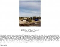 The J pole vertical for 14MHz is built from a fifty-foot TV push up mast by Mike Higgins, K6AER
 -
 Selecting an appropriate antenna system for shortwave broadcasting involves evaluating various types based on performance, cost, and operational parameters. This resource details the critical specifications for broadcast antennas, including average and peak power ratings, directivity, takeoff angle (TOA), horizontal beamwidth, and gain, emphasizing that a 100-kW transmitter requires an antenna rated for 150 kW average and 400 kW peak. It clarifies that low TOA signals travel thousands of kilometers, while high TOA is for local coverage, and nearly all modern shortwave broadcast antennas are horizontally polarized. The article explores specific antenna types, such as Log-Periodic Antennas (LPAs), which offer wide frequency ranges (e.g., 2-30 MHz) and directional patterns with 11 dBi gain, costing from $20K to over $100K for multi-curtain versions. Dipole arrays, also known as curtain antennas, are prevalent in international broadcasting, featuring steerable beams (±15° and ±30°) and mode-switching capabilities to alter TOA, with high/low pairs costing over $1 million. Fan dipoles are noted for omnidirectional patterns, smaller size, and lower cost for low-power applications, while rhombics, though simple, require resistive termination and incur several dB of I2R losses. Balun considerations are crucial, as most communications baluns are not rated for the higher average and peak powers of AM broadcast transmitters. Modern shortwave antennas utilize durable materials like Alumoweld wire rope for radiators and support elements, avoiding copper, fiberglass, or materials prone to stretching or deterioration. Feeder systems for high-power stations often require tapered-line baluns to convert 50-ohm unbalanced power to 300-ohm balanced for connection to the antenna.
 -
 This article describes the construction of a Moxon rectangle antenna for the 70MHz (4-meter) amateur radio band. This compact two-element beam design features folded element ends, reducing its width to approximately 75% of a half-wavelength. The antenna was built using enamelled copper wire stretched over a lightweight fiberglass kite spar frame, with a direct coaxial cable feed connection. Initial testing showed a VSWR of around 1.3 with distinct nulls at 90 degrees when horizontally mounted. The author later tested vertical polarization and suggested that the antenna's compact size might allow for indoor loft installation.
 -
 Indoor multiband dipole with EZNEC data files for simulation and analysis. Includes details on construction, tuning, SWR plots, and software usage. This page includes two different dipoles, a first version for 20-10 meters and an extended version covering 40-10 meters allowing a full coverage of most used ham radio HF Bands.
 -
 S Meter Lite is a no-cost program that displays your receiver's S Meter signal strength in a window by W8WWV
 -
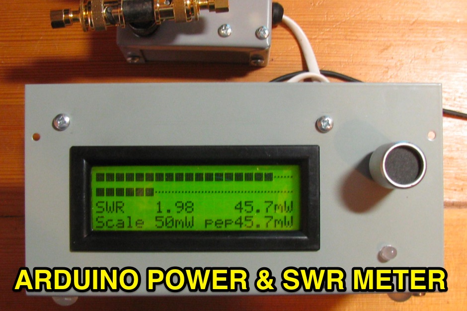 Power and SWR Meter with dual bargraphs and sticky bar, using 2x AD8307
 -
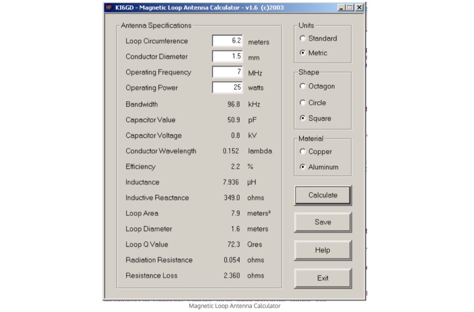 Free windows program to calculate magnetic loop antenna.This small loop antenna calculator allow to determine capacitance and voltage based on Loop circumference, desired resonant frequency, conductor diameter and the operating power
 -
 A **90-foot tall** top-loaded vertical antenna for the 160-meter band is detailed, constructed from aluminum irrigation tubing. The design incorporates four sets of four guy wires for structural stability, essential for an antenna of this physical size. This _monoband_ vertical is optimized for low-band operation, providing a robust solution for DXing and contesting on 1.8 MHz. The document includes specific construction methods for assembling the aluminum irrigation tubing sections and securing the guy wires. While a full NEC model is not explicitly provided, the physical dimensions and construction materials are sufficient for replication by experienced builders. The antenna's height and top-loading configuration are critical for achieving efficient radiation on 160 meters, particularly in minimizing ground losses.
 -
 The **NW3Z** optimized wideband antenna designs, originally presented at Dayton 2001, detail Yagi configurations for the 20-meter, 15-meter, and 10-meter amateur radio bands. This resource provides access to the design files, likely containing critical parameters such as element spacing, element lengths, and boom dimensions, which are essential for replicating these directional antennas. The designs focus on achieving wide bandwidth, a desirable characteristic for contesters and DXers operating across a significant portion of each band. The content specifically references "nw3z-Antenna-DesignsDownload," indicating that the core information is available as a downloadable file, presumably in a format suitable for antenna modeling software or direct construction. Such files typically include **NEC models** or similar data, allowing for performance analysis and optimization before physical construction. The emphasis on "optimized wideband" suggests design considerations for SWR bandwidth and gain characteristics over a broader frequency range than typical narrow-band Yagis. The resource serves as a direct source for specific, proven antenna designs from a known amateur radio antenna designer, offering practical data for hams interested in building high-performance Yagi arrays for HF.
 -
 10 Meter WonderBar Antenna, present an SWR 1:1 over entire band, great DX, rotateable by hand, 8 ft long - build for about $20
 -
 Over 45 years of amateur radio experience inform the homebrew projects detailed on this personal website, with a particular focus on microwave frequencies. The site showcases a 24 GHz transverter and a more recent 47 GHz transverter, demonstrating practical construction techniques for extreme high-frequency operation. These projects often involve custom circuit design and careful component selection to achieve stable performance at millimeter-wave bands. Key projects include a _harmonic converter_ for frequency measurement and a tracking spectrum analyzer, essential tools for microwave experimenters. The site also documents a CW sidetone generator and a TX/RX sequencer, illustrating fundamental building blocks for radio equipment. Details on a digital frequency meter and an S-meter/dBm meter provide insights into test equipment construction. Specific achievements, such as a **24 GHz** tropo QSO with DK3SE in 2021, highlight the operational success of these homebrewed systems. The content reflects a long-standing dedication to self-sufficiency in amateur radio, providing practical examples for those interested in building their own gear.
 -
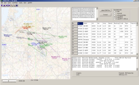 adsbScope is a freeware Windows application designed for processing _ADS-B_ (Automatic Dependent Surveillance-Broadcast) frames received from a compatible decoder. It identifies aircraft, calculates their real-time positions, and presents flight parameters in both alphanumeric tables and a graphical display. The software interfaces via a virtual COM port, receiving raw frames to provide detailed situational awareness, including a global coordinate grid, continental coastlines, over 4,000 **airport** locations, and major cities. Users can overlay OpenStreetMap tiles and view world state boundaries, with each tracked aircraft rendered with labels showing altitude, speed, heading, squawk code, and flight identifiers. When paired with the adsbPIC-decoder, adsbScope enables advanced hardware control, allowing users to toggle data filters for specific frames like DF17/18/19, adjust analog signal thresholds for reception fine-tuning, and manage system resets or bootloader activation directly from the PC. This functionality provides a customizable toolkit for hobbyist radar listeners, offering a robust alternative to commercial tools for processing aircraft data. The software displays up to **1090 MHz** transponder data and can track aircraft up to 250 nautical miles.
 -
 A 2-meter Turnstile antenna, detailed for amateur satellite communication, offers a straightforward build for those looking to engage with orbiting transponders. The author, WB8ERJ, shares his personal design and construction methods, emphasizing the antenna's simplicity and effectiveness for LEO (Low Earth Orbit) satellite work. This design provides a circularly polarized signal, crucial for mitigating _Faraday rotation_ and signal fading often encountered with linearly polarized antennas when tracking satellites. Construction involves readily available materials like PVC pipe and copper wire, making it an accessible project for many hams. The article includes practical advice on element spacing and feed point considerations, drawing from the author's hands-on experience in the shack and field. It highlights the antenna's utility for receiving signals from various amateur satellites, including the popular AO-91 and AO-92. The Turnstile's inherent omnidirectional pattern in the horizontal plane, combined with its circular polarization, yields consistent signal reception, often resulting in **stronger decodes** and **more reliable contacts** compared to basic dipoles or verticals.
 -
 The BV6 50 MHz Yagis resource details the construction of two distinct Yagi antenna designs for the 6-meter band, specifically a 1-wavelength (1wl) model and a 2.1-wavelength (2.1wl) model. The 1wl Yagi, with a boom length of 5.850m, achieves a gain of **9.4 dBd**, while the 2.1wl Yagi, spanning 12.90m, boasts a gain of **11.9 dBd**. These designs adhere to a proven methodology for optimizing current slope and maintaining constant phase delay across parasitic elements, ensuring high gain per boom length and an _excellent pattern_. Both designs target a 50-ohm input impedance, facilitating straightforward feeding with a robust folded dipole. Final verification using NEC-II software confirmed the antennas' exceptional stacking capabilities, yielding stacking gains exceeding **5.8 dB** for a 2x2 array with minimal mutual detuning. The resource provides common mechanical data, including boom and element diameters, and specifies element lengths corrected for boom diameter. While the original _DUBUS Technik V_ publication contained incorrect element lengths, this resource provides the accurate dimensions for proper construction, emphasizing the use of readily available materials for cost-effective amateur radio deployment.
 -
 Over 70 international contests are supported by YPlog, a Windows-based logging and radio control program designed for amateur radio operators. This software integrates with various digital mode applications like _WinPSK_, _HamScope_, and _MMTTY_, facilitating partially automated log entry for modes such as PSK31, CW, and RTTY. It provides comprehensive logging capabilities including QSL label printing, beam headings, and dup-checking, alongside award tracking for DXCC, ITU/CQ zones, IOTA, Grid Locators, and Counties. The program offers advanced contesting features, including multi-multi or multi-2 networked operations with automatic log data sharing, multiple Cabrillo submission formats, and configurable CW keyboard layouts. Device support extends to TR-compatible CW keying, SO2R control with Top-Ten devices like the DX-DOUBLER, and internal W9XT digital voice keyer integration. YPlog is notable for its support of the _OK1RR DXCC_ country resolution files, providing a robust historical DX compendium. Beyond logging, YPlog includes two freeware utilities: one for computing design parameters for coaxial traps and another for displaying and printing azimuth and Mercator maps from the operator's QTH. The software runs on Windows 95/98/ME/NT/2K, with a recommended screen resolution of 1024x768. Registration costs **$50.00 US** to unlock all features, including full contesting capabilities and rotator control.
 -
 The Elecraft K3, a popular HF transceiver, is often benchmarked against new market entrants. This article critically compares the Kenwood TS-590S to the K3, focusing on key technical specifications and operational aspects relevant to serious amateur radio operators. The author proposes three distinct evaluation methods: a circuit diagram comparison, an independent review analysis (referencing Peter Hart, G3SJX, in RadCom), and a real-world "ear test" by experienced contest operators on 40 and 80 meters. The analysis delves into specific receiver components, including the first mixer design, RF and IF amplifier performance, and the presence of an image noise filter. It highlights the K3's switched mixer and the potential for the TS-590S to utilize similar or improved designs, such as a classic filter with enhanced selectivity. The article also scrutinizes the second mixer stage, noting the K3's SA612 chip and its associated IP3 limitations, suggesting Kenwood might achieve benefits with a different mixer architecture. Further points of comparison include DSP capabilities, where the K3's high-performing DSP with KK7P's involvement is noted against the TS-590S's potential reliance on newer IC technology but possibly less refined software. The discussion extends to DDS and PLL implementations for phase noise and spurious emissions, and the utility of a second receiver for DX chasing and contesting, acknowledging its importance for some operators while being less critical for others. The article concludes by emphasizing personal preference in equipment selection.
 -
 This meter scale drawing program is designed to have a computer do the hard work in making a precision scale for a d'Arsonval analog meter. The resulting scales will typically be nicer-looking than those found on many commercial meters.
 -
 An option for restricted and limited space, to operate the six meters band with an indoor three elements yagi antenna by Brian Williams
 -
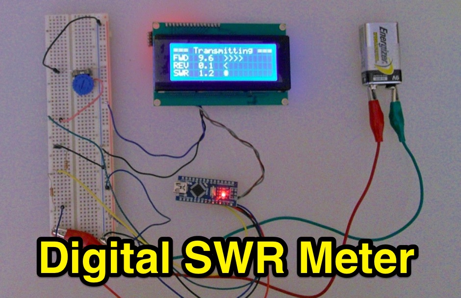 Inline RF Power & VSWR Meter. A DIY meter 0 to 30 Watt with Average and Peak. Circuit Description, Arduino Nano software code and part list to DIY your own Digital SWR Meter
 -
 End-Fed Half-Wave Antennas (EFHWAs) are analyzed for their utility in portable QRP operations, emphasizing their simplicity, efficiency, and predictable radiation patterns compared to other portable antenna types. The discussion contrasts EFHWAs with vertical antennas, random length wires, and center-fed dipoles, highlighting the common pitfalls of each, such as ground system dependency for verticals and feedline issues for dipoles. The article details the electrical half-wavelength calculation using the formula L (Ft) = 468/F(MHz) and explains how EFHWAs can be resonant on harmonic frequencies, enabling multiband operation. Various deployment configurations are presented, including the inverted L, inverted Vee, sloping wire, and vertical setups, each with specific advantages for radiation angle and polarization. For instance, a vertical EFHWA offers a low angle of radiation suitable for DX contacts without requiring an extensive ground system. The resource also addresses the counterpoise requirements, suggesting a quarter-wavelength wire or connection to a metallic structure for decoupling. A schematic diagram for a simple parallel-tuned circuit tuner, based on the _Rainbow Bridge/Tuner_ design, is provided, detailing component values for 30 and 40 meters, including a 6 microhenry toroidal inductor and a 20-100 picofarad mica compression capacitor. The tuner's adjustment process for SWR matching is also outlined.
 -
 HotPaw MorseDecoder, an iOS application, provides real-time translation of Morse Code audio signals into plain text, leveraging the device's microphone or headset input. It incorporates a DSP narrow-band audio filter, adjustable from 300 to 2400 Hz, to mitigate background noise and QRM, enhancing signal clarity for decoding. The application offers both an automatic decoding mode and manual controls for fine-tuning parameters such as audio filter frequency, WPM dot/dash speed, noise threshold, and Farnsworth timing. The WPM detection automatically adapts from 8 to 40 WPM, with a QRQ High Speed mode extending this range to 30-80 WPM for faster code. A built-in spectrogram aids in identifying the precise audio frequency of the CW tones. User feedback indicates effective performance with various transceivers like the Yaesu FT-857 and Icom IC-R8600, particularly when manual settings are optimized. The app's ability to visually tune stations within the passband and decode speeds beyond an operator's manual capability has proven beneficial during contests and general QRP operation.
 -
 This PDF document, authored by KT4QW in October 2004, details the construction and modeling of a dual-band, horizontally polarized hanging rectangular loop antenna for **10 and 17 meters**. The design, adapted from *The ARRL Handbook*, utilizes _NEC4WIN95_ software for scaling and optimization, targeting a 50 ohm feedpoint impedance. The resource includes a bill of materials, step-by-step construction instructions, and a discussion of the antenna's radiation characteristics. It presents NEC-generated elevation and azimuth patterns, comparing the loop's performance to a half-wave horizontal dipole at the same height and frequency. The 17-meter element is centered at 18.140 MHz for low SWR across the phone band, while the 10-meter element is centered at 28.500 MHz. Construction involves 14-gauge stranded copper wire and Schedule 40 PVC spreaders, with the total wire length calculated by the formula: Length in feet = 1005/MHz. The feedpoint impedance can be adjusted by modifying the rectangular aspect ratio. The document specifies hoisting the antenna to at least a half-wave above ground for testing. It notes that a balun was tested and found to have no measurable effect on SWR or radiation characteristics. A 2-meter scale model is presented to illustrate the physical design, and a "rotator" string is incorporated for directional adjustment up to 90 degrees.
 -
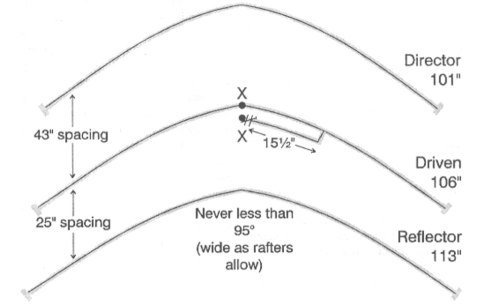
 The document discusses a two-element parasitic Delta-Loop array for the 40 meters band, aimed at radio amateurs interested in antenna projects. It provides detailed plans and instructions for building a homemade Delta-Loop antenna.