Search results
Query: ground antennas
Links: 101 | Categories: 3
-
 Demonstrates the construction of a **multi-band HF mobile antenna** utilizing a modified CB whip antenna base. The resource details the process of stripping a commercial CB whip, winding a new helical coil with 0.7mm insulated copper wire, and identifying tapping points for various HF bands. It emphasizes the importance of a rugged, slim design for mobile operation, discussing mechanical length, power handling (up to 200 watts), and coil diameter considerations. The article includes a graphic illustrating the antenna's operational principle, where sections of the helical coil are shorted from bottom to top to maintain efficiency and high Q. The resource presents a practical approach to achieving **band switching** without an external tuner, by manually adjusting tapping points on the coil. It provides a table with reference lengths in centimeters from the feedpoint for 7 MHz (40m) through 28.7 MHz (10m), including WARC bands. The author details mounting techniques, suggesting a Diamond bracket for secure attachment to a vehicle trunk, and stresses the critical role of proper grounding for optimal performance. The design allows for operation on 75m and 80m bands by adding a 110mm steel whip.
 -
 Author evaluated a custom-built passive AM loop antenna, achieving notable DX reception including KLBJ Austin (230 miles) and WWL New Orleans (700 miles). The antenna operates solely on resonant inductive coupling, enhancing weak signal reception without external amplification. This project illustrates how fundamental RF design—calculating inductance, capacitance, and Q factor—can significantly boost performance of consumer-grade radios. Detailed construction techniques, theoretical background, and optimization strategies for effective loop antenna design are presented for amateur and experimental use.
 -
 2-Element parasitic Yagis for the Shortwave-Bands 10-12-15-17-20-30m. The antennas are feeded with the DK7ZB-match. A quarter-wave choke of coax is grounded at the socket.
 -
 The **Extended Double Zepp** (EDZ) antenna, a simple wire design, is presented as a means to achieve 3-4 dB of gain on 10 meters, with an overall length of just 43 feet. This resource, authored by WB3HUZ, details several gain antennas suitable for the 29 MHz AM segment, all modeled using EZNEC software at 30 feet above ground. Other designs include a compact rectangular loop, offering more gain than the EDZ and a lower take-off angle, and the **Lazy H**, a bidirectional antenna providing 6 dB gain, which is also workable on 20, 17, 15, and 12 meters. The Bisquare, a diamond-shaped open-top loop, is also featured, providing approximately 4 dB gain and requiring only a single support. These designs are primarily fed with ladder line or open-wire line to simplify matching, though a coax feed option for the EDZ is shown for 10-meter-only operation. The Lazy H, for instance, requires about 16 feet of open-wire line for its half-wavelength elements spaced a half-wavelength apart. An enhanced EDZ Lazy H variant is also discussed, achieving an additional 1-2 dB gain by extending element length to 1.28 wavelengths and increasing spacing to 0.64-0.75 wavelengths. The Bisquare, while primarily a 10-meter antenna, can be adapted for 20 meters by closing the top connection.
 -
 Here is a sure fire way to make end-fed halfwave antennas fed with a 50 ohm coupler work - without long radials, grounds, chokes, voodoo.
 -
 Build your mobile antenna which outperforms Hustler by 10db and ATAS-100 by 18db. From 80 to 10m. The HB9ABX mobile HF antenna, designed for 10 to 80 meters, was developed by Felix Meyer and outperforms commercial antennas like HUSTLER and YAESU ATAS-100/120 in field tests. Made from fiberglass rods and enamelled copper wire, it includes a loading coil with adjustable taps for tuning across bands. Installation requires solid grounding, and adjustments are made via whip length and coil settings. An antenna tuner ensures optimal SWR. Users must handle fiberglass with care due to health risks. This design proved highly effective in South America and Europe.
 -
 The J-Pole antenna is an omnidirectional antenna that can be used for base, mobile and field day stations. It does not need a ground plane, radials or a complicated matching system. The J-Pole can be cheaply, simply and quickly constructed using a variety of techniques, some of which are discussed in this article.
 -
 The RXO Unitenna, a vertical wideband antenna, offers operation across the 7-21 MHz spectrum, covering the 40, 30, 20, 17, and 15-meter amateur bands. This design focuses on achieving a low SWR across a broad frequency range, making it suitable for general HF operation without requiring an external antenna tuner for minor SWR variations. The antenna utilizes a unique loading coil and matching network to maintain efficient radiation characteristics across its operational bandwidth. Construction details within the PDF document include specific dimensions for the radiating element and the counterpoise system, which is critical for vertical antenna performance. The design incorporates readily available materials, simplifying the build process for radio amateurs. Performance graphs illustrate the SWR characteristics across the 7 MHz to 21 MHz range, demonstrating the antenna's wideband capabilities. The document also provides guidance on feedline connection and grounding considerations for optimal field deployment. This vertical antenna configuration is particularly useful for hams with limited space, offering a compact footprint compared to horizontal wire antennas.
 -
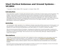 This article describes how an effective ground system can be produced for a short vertical antenna.
 -
 Suggestions on finding RF ground when you live in an apartment and you want to setup an antenna
 -
 End-Fed antennas are NOT balanced systems; but neither are verticals, ground planes, discones, windoms, zepps, Marconis, half-slopers, et al. Additionally, the low-impedance antenna port of your transmitter/receiver is not balanced.
 -
 This Vertical antenna design by David Reid for lower bands focuses on achieving effective DX communication by optimizing the antenna low-angle radiation for long-distance contacts. The design incorporates techniques like linear loading and capacity hats to reduce the antenna's height while maintaining performance, especially on 40m and 80m bands. Building a solid ground plane and using quality materials ensure efficiency and durability. Although vertical antennas can be complex to build, this project simplifies the process, making it accessible for ham operators seeking strong, reliable signals.
 -
 How High should my Dipole be? Dipole Antennas and the effect of height above ground. The effectiveness of a dipole antenna is influenced by its height above ground, determined by the intended use such as DX work, local communication, directionality, omni-directionality, and feed point impedance. Through EZNEC modeling, the study evaluates a 40-meter dipole's performance at various heights, from 7 to 560 feet. Findings reveal that lower heights enhance omni-directional local communication, while higher placements favor DX work with low-angle radiation. The study emphasizes the importance of defining operational goals to optimize dipole height and performance.
 -
 Details the construction and optimization of antenna systems for amateur radio satellite operations, focusing on practical, homebrew solutions for VHF/UHF bands. It covers building _groundplane antennas_ from salvaged materials, recycling old beam antennas into new configurations like a 2-meter crossed yagi, and constructing a 10-meter horizontal delta loop. The resource also explains antenna matching techniques, including folded dipole driven elements and quarter-wave transformers, along with the importance of accurate SWR measurements and minimizing coax loss. Demonstrates how to achieve a **1:1 SWR** by carefully trimming elements and adjusting radial angles on groundplane antennas. It provides insights into selecting appropriate coax and connectors, highlighting the benefits of Belden 9913 for low loss and the proper installation of _N-connectors_. The article also addresses RFI mitigation from computer birdies and presents a design for a silent triac antenna control circuit, offering practical solutions for common satellite station challenges.
 -
 How to build a beverage antenna. How to deploy a BOG antenna for your next SWL DX-ing activity. Give it a try and follow the orientation tips for this bi-directional antenna.
 -
 Types of beverage wires, choose best supports and insulators, multiple antennas at one feedpoint, all well documented with photos and exaustive explanation. This article offers insights on building Beverage antennas for optimal reception. Key takeaways include using strong wire (copperweld or electric fence), proper termination, and a good grounding system (multiple copper rods). The author recommends maximizing antenna length and orienting it towards desired stations. For best results, utilize an antenna tuner and experiment with termination resistors.
 -
 The Bruce array is a simple, often-forgotten wire antenna array that is advantageous for 80 and 160 meters, where typical gain antennas are very large. This bi-directional broadside vertical array is only 1\4 lambda high and does not require a ground system. It offers substantially greater SWR bandwidth than the half-square or bobtail curtain. A 4-element Bruce array used by N6LF showed a gain of about 4.6 dB compared to a 1\4 lambda vertical with 8 elevated radials, with a 2:1 SWR bandwidth greater than 400 kHz. The antenna is simple and its dimensions are flexible.
 -
 How High should my Dipole be? Dipole Antennas - the Effect of Height Above Ground
 -
 Perfect ground vs. poor ground. What is the difference? How does the ground influence the DX-gain?
 -
 Interesting article on mobile antennas by Cebik. . The article offers advice for setting up and operating mobile antennas for ham radio use. It emphasizes the lossy nature of mobile-in-motion antennas but encourages users to rise to the challenge. Steps include safeguarding car electronics, choosing proper cabling, and carefully selecting and mounting antennas. It highlights potential issues like roof mounting, trunk lip grounding, and side-mounting for trucks. For stationary operation, options like dipoles or beams are explored, with safety tips for masts and guying systems. Lastly, it stresses safety, suggesting stopping the vehicle to operate whenever possible
 -
 Technical reference about Accessories, Amplifiers, Antennas, Cable and Connectors, Filters, Geography, Grounding, Gunk, Matching Networks, Projects, Propagation Info Radios, RFI/EMI, Rotors, Station Setup, Towers.
 -
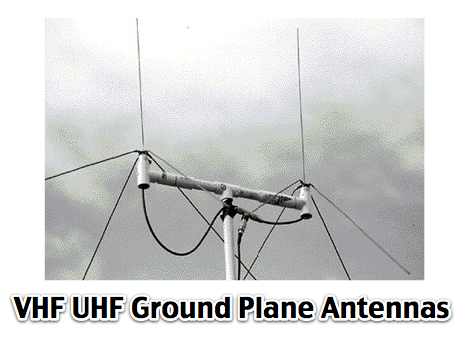 Phased array Ground Planes antennas for 144 Mhz
 -
 Inverted V antennas is a dipole with the center raised on a mast and the endpoints near ground. Calculate dimensions online.
 -
 Java script antenna calculators for ground planes, half wave verticals, quad antenna, 5/8th wave vertical antenna, dipole and inverted vee antennas
 -
 End-Fed Half-Wave Antennas (EFHWAs) are analyzed for their utility in portable QRP operations, emphasizing their simplicity, efficiency, and predictable radiation patterns compared to other portable antenna types. The discussion contrasts EFHWAs with vertical antennas, random length wires, and center-fed dipoles, highlighting the common pitfalls of each, such as ground system dependency for verticals and feedline issues for dipoles. The article details the electrical half-wavelength calculation using the formula L (Ft) = 468/F(MHz) and explains how EFHWAs can be resonant on harmonic frequencies, enabling multiband operation. Various deployment configurations are presented, including the inverted L, inverted Vee, sloping wire, and vertical setups, each with specific advantages for radiation angle and polarization. For instance, a vertical EFHWA offers a low angle of radiation suitable for DX contacts without requiring an extensive ground system. The resource also addresses the counterpoise requirements, suggesting a quarter-wavelength wire or connection to a metallic structure for decoupling. A schematic diagram for a simple parallel-tuned circuit tuner, based on the _Rainbow Bridge/Tuner_ design, is provided, detailing component values for 30 and 40 meters, including a 6 microhenry toroidal inductor and a 20-100 picofarad mica compression capacitor. The tuner's adjustment process for SWR matching is also outlined.
 -
 There are many kinds of satellite antennas that will get you on the birds and allow you to have lots of fun
 -
 Bill Orr W6SAI ham radio techniques. Improving ground connection, computer analysis of the antenna, modelling sample antennas pdf file
 -
 G4URH calculations to design your own antennas, ground plane, half wave antennas, Quad Antennas and 5/8 verticals
 -
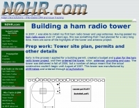 Ham Radio Tower Project at N0HR. Includes site plan, escavation, tower construction, HF antennas, grounding and lightning protection, coax and more.
 -
 JJ0DRC's HF multi-band delta loop antenna project, initially conceived during the waning peak of Cycle 23, addresses the common challenge of achieving effective DX operation from a small residential lot in Japan. Dissatisfied with a ground plane antenna's performance in SSB pile-ups, the author sought a beam-like solution without a tower, drawing inspiration from a JJ1VKL article in CQ Ham Radio Sep. 2000. The antenna, constructed in October 2000, employs two 7.2-meter fishing rods (37% carbon fiber, reinforced with cyano-acrylate glue and aluminum tape) and 1mm enameled wire, fed by an Icom AH-4 external antenna tuner. While the exact beam pattern remains unmeasured, JJ0DRC observed a significantly higher callback rate compared to dipole antennas, particularly on higher bands. The system's circumference length of 15-20m is crucial for maintaining a good beam pattern across HF bands, though performance on lower bands like 80m, 40m, and 30m becomes less directional as the length deviates from a full wavelength. Ongoing maintenance addressed degradation issues, including aluminum tape cracking and wire breakage at connection points due to strong winds (often exceeding 10-15m/s in winter). The author reinforced rod connections with IRECTOR PIPE SYSTEM components and INSU-ROCK ties, and improved wire attachment methods using Cremona rope and epoxy bond to enhance durability.
 -
 A quarter wave vertical end-fed antenna for the 40 meters band. As all vertical antennas, also this aerial requires a good earthing system. In this project the ground is composed by twelve 4, wires buried in the lawn by using a spade to create a slit to drop the wire into.
 -
 An introduction to antennad including a DIY assembly instruction for a A Ground Plane Antenna for NOAA Weather Stations
 -
 Radial systems for elevated and ground mounted vertical antennas by SteppIR
 -
 The page discusses Axial-Mode Helical Antennas, focusing on turning helical antennas over perfect ground and modeling helices in NEC-2 for optimized design. It covers topics such as high-gain performance, broadband, impedance matching, radiation pattern, feedline, balun, near field, far field, and DIY applications.
 -
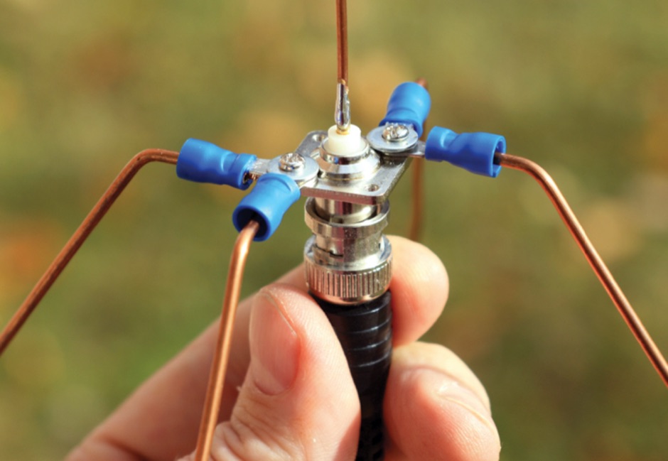
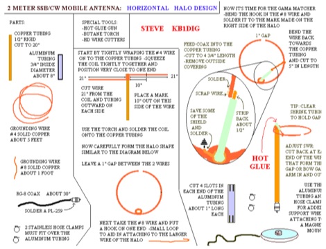 This HALO design is not ground dependent and can be mounted atop a section of PVC.
 -
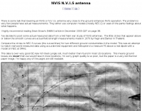 Lowering an NVIS or N.V.I.S. antenna very close to the ground enhances NVIS operation
 -
 One of the most useful antennas in the repertoire is the Marconi or quarter wave grounded vertical antenna. Its invention made it possible to halve the length of antennas, simplifying communications, especially at HF and below.
 -
 Notes on Axial-Mode Helical Antennas in Amateur Service. Helix Basics, Modeling Issues, and Short Helical Antennas Over Perfect Ground
 -
 A 50-ohm 10W resistor forms the core of this portable QRP antenna, designed by _K0EMT_ for convenient operation on 160m and 80m. The construction involves soldering the resistor to a BNC connector, with one lead to ground and the other to the center conductor, then insulating the assembly. This minimalist design aims to provide a highly portable solution for low-band QRP operations, acknowledging the inherent trade-offs between antenna size and efficiency. Testing with an antenna analyzer revealed low SWR on both 160m and 80m, with a Yaesu FT-817 confirming good matching. While 40m and 30m showed higher SWR, the primary focus remains on the lower bands. The author successfully tested the antenna with **2.5W CW** output, demonstrating its practical application for QRP field operations where ease of deployment is paramount, even if it means sacrificing some **gain** compared to full-sized antennas.
 -
 Windows program for analyzing vertical antennas. This program shows the resistance and reactance to be expected looking into a cylindrical metallic tower over a perfect ground. It gives a useful approximation of the values to be expected in a real-world situation.
 -
 A project of a 5 Antennas Relay Switch Box, all Switches & Relays have both contacts wired in parallel to improve reliability of operation, to prevent static build up, when an antenna is not in use the feeder coax is grounded.
 -
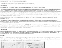 All antennas that are situated close to the ground are affected by that ground to some extent. This article explain effects and benefits of counterpoise.
 -
 A very efficient 80 meter Counterpoise antenna designed to reduce ground losses from inadequate radial systems beneath inverted L antennas, a project by DM2GM and DM4IM based on the original K2AV antenna concept.
 -
 Guide to ground mounting antennas, notes on efficiency, elevated installations, metal towers and masts, other mounting schemas, moble homes and rv, lightning protections, artiche by Bencher
 -
 This article compares two commercial vertical antennas for the 4-meter amateur radio band: the Watson WVB-70 half-wave and the Sirio CX4-71. The Watson measures 2.03m in length, costs around £40, and exhibited adequate performance but required additional waterproofing after rain affected its VSWR readings. The longer Sirio CX4-71 (3.02m) performed noticeably better, delivering signals approximately 2 S-points stronger than the Watson. The Sirio demonstrated high build quality, a stable 1.2-1.4:1 VSWR, and weather resilience, though minor VSWR fluctuations were observed during rain and frost. Both antennas are half-wave designs requiring no ground plane radials.
 -
 This resource details the four primary functions of a ground system: lightning energy dispersion, equipment safety, RF return path provision for end-fed antennas, and management of induced RF currents. It clarifies that a ground system's effectiveness varies depending on its specific function, noting that a good lightning ground might not be an effective RF ground. The content emphasizes that proper antenna system design, including baluns and appropriate feedline lengths, often negates the need for an RF station ground to mitigate common mode currents or RFI in the shack. The article quantifies lightning energy, stating its peak is in the dozens or hundreds of kilohertz, with damaging energy extending to hundreds of megahertz, and currents reaching thousands of amperes. It recommends solid, wide, smooth copper surfaces for ground leads to achieve low impedance across a wide frequency range. The author, W8JI, shares practical insights from his station, which includes two 300-ft towers and four 130-ft wire verticals, detailing his use of common point grounds and _DX Engineering RR-8 HD_ antenna switches for lightning protection without coaxial surge protectors. Specific examples of antenna systems prone to common mode current problems are listed, such as random wire antennas without proper feedline lengths and off-center fed dipoles. The text also explains how a ground screen or radial system can reduce local noise sensitivity for vertically polarized antennas by covering the lossy earth.
 -
 Ground Plane - 1/4 wave vertical, J-Pole, 3 Element Yagi Beam and simple antenna supports
 -
 Mounting on Roof or at Ground Level? Why ground plane antenna works better at lower level.
 -
 Butternut article on radials usage on vertical and ground plane antennas
 -
