Search results
Query: hf receiving antenna
Links: 21 | Categories: 1
-
 The 160/80m coaxial receiving loop antennas are designed to enhance reception on the top bands while minimizing noise. These antennas are particularly beneficial for operators with limited space, as they can be constructed using lightweight materials, making them portable and easy to deploy. The standalone 80m loop has a diameter of approximately four feet, allowing for easy rotation and installation above existing VHF antennas. Over the years, many amateur radio operators have turned to loop antennas as a viable alternative to traditional beverage antennas. The design allows for significant noise reduction, especially when paired with a quality pre-amplifier. Experimentation with various configurations has led to the discovery that diamond-shaped loops provide optimal performance. Users have reported a noticeable improvement in signal quality, making these loops a valuable addition to any low-band DXing setup.
 -
 Base station and repeater antennas, mobile antennas, ,multi-band HF antennas , handheld transceivers, receiving and scanner antennas, power meters, swr meters, power supplies, coaxial switches
 -
 HF receiving loop antenna, an easy-to-make receiving loop antenna for HF
 -
 WiNRADiO Communications, a division of Radixon Group, was established in 1996 to commercialize extensive research in radio communications. The company specializes in integrating radio and computing technologies, offering a diverse product range for government, military, security, and amateur radio enthusiasts. Their product line includes the WR-G65DDCe 'EXCALIBUR Sigma' HF/VHF SDR receiver, noted for its capabilities, and the G31DDC EXCALIBUR, recognized for its price/performance ratio in shortwave listening with improved AMS and Noise Blanker features. The company also produces the G39DDC series EXCELSIOR for serious monitoring, WR-G526e/G527e/G528e modular SDR solutions for high-performance applications like phase-coherent direction finding, and the low-cost WR-G305e/G305i VHF/UHF receivers. Professional counterparts, the WR-G315e/G315i, support APCO P25 decoders and trunking options. WiNRADiO's offerings extend to the PFSL-G3 field strength logging system for mobile signal coverage, advanced multichannel telemetry systems like the MS-8323, and specialized antennas such as the AX-31C Log-Periodic and AX-81S active HF antenna. DRM decoder software is available for G3 Series receivers, enabling clear reception of DRM broadcasts. The WSS-420 Weather Satellite Receiving System and various antenna rotators are also part of their product ecosystem. WiNRADiO supports multiple operating systems, with MacRadio for Apple Macintosh users and LiNRADiO for Linux developers, providing drivers and network receiver solutions like the RLX-810.
 -
 For radio amateurs seeking compact and efficient antenna solutions, particularly for restricted spaces or noise reduction, HF loop antennas present a viable option. This resource compiles several articles from the ARRL, detailing the theory, design considerations, and practical construction of various loop configurations. Topics include small transmitting loops, receiving loops, and multi-band designs, often emphasizing their performance characteristics such as directivity, bandwidth, and impedance matching. The collected articles provide insights into the comparative performance of different loop geometries, such as circular versus square loops, and discuss the impact of conductor size and tuning methods on efficiency. Practical applications are explored, including their use in portable operations, stealth installations, and urban environments where noise mitigation is critical. The content often includes construction diagrams, parts lists, and performance data derived from modeling or field tests, enabling hams to replicate or adapt the designs for their specific operating conditions.
 -
 Demonstrates the construction and measurement of a single-turn HF receiving loop antenna, built from common materials like electrical conduit and lamp cord. The resource details the physical dimensions, including a 4-meter circumference, and calculates the theoretical inductance at approximately _6.4 uH_. It outlines a method for determining resonant frequencies across the 4-17 MHz range using a _C Jig_ and a _VR-500 receiver_, coupling the loop with a ferrite ring. The article also discusses the impact of receiver coupling on the loop's Q factor, noting a degradation in sharpness due to the transformer's reflected impedance. Analyzes the observed resonant frequency patterns, highlighting an unexpected rise in the loop's effective inductance at higher frequencies, particularly above 13 MHz. While some increase is attributed to distributed capacitance, the rate of rise suggests further investigation. The experimental setup provides practical insights into the challenges of maintaining high Q in simple receiving loops and offers a comparative reference for other homebrew antenna projects, such as those by _VK2TPM_.
 -
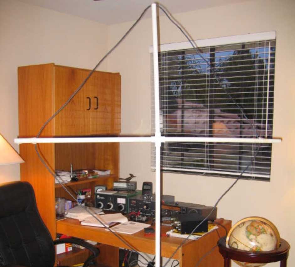
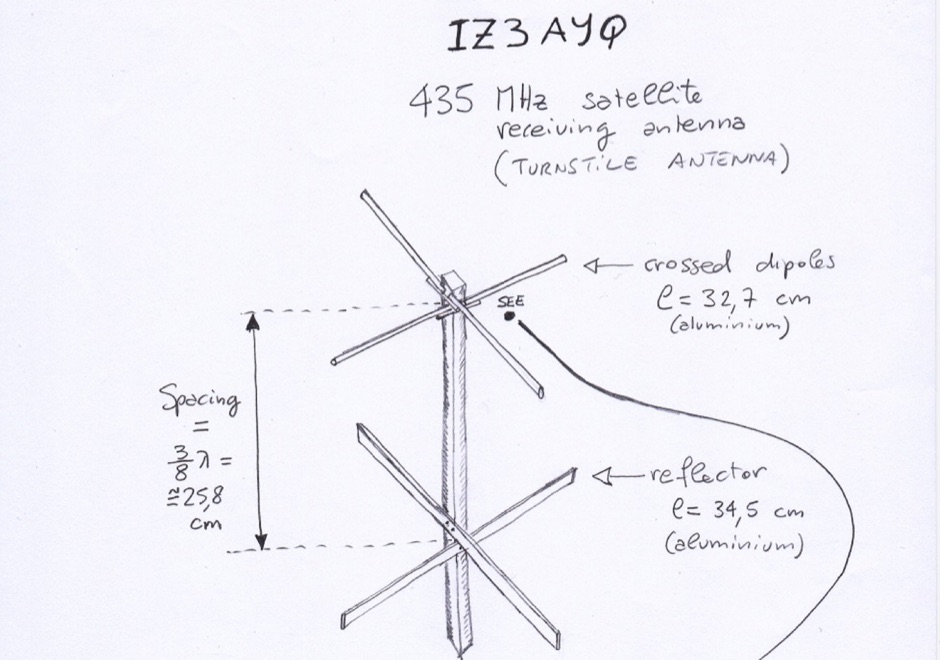 A UHF antenna for satellite reception. Anntenna mast is in wood, made with two aluminium rods
 -
 The _Italian VHF Beacons_ resource provides a detailed listing of active and QRT amateur radio beacons operating across VHF, UHF, and SHF bands within Italy. Each entry specifies the beacon's callsign (e.g., IQ1SP/B), operating frequency (e.g., 144.411 MHz), QTH locator (e.g., JN44VC), effective radiated power (ERP) in watts, and antenna configuration (e.g., Big Wheel, 4x Dipole, Yagi). This data is crucial for radio amateurs involved in propagation studies, equipment testing, and long-distance (DX) communication on these higher frequency bands, offering fixed signal sources for monitoring. This compilation, last updated in October 2005, serves as a historical snapshot of Italian beacon activity. For instance, it lists several 144 MHz beacons with ERPs ranging from **0.1W** to **10W**, and higher frequency beacons such as I8EMG/B on 1296.880 MHz and I3EME/B on 24192.132 MHz. The inclusion of QRT (Quiet Radio Teletype) status for many entries indicates the dynamic nature of beacon operations over time. Users can utilize this information to identify potential signal sources for band openings or to calibrate their receiving equipment against known transmissions.
 -
 Hi-Z Antennas offers specialized high-impedance receiving systems, primarily focusing on phased vertical arrays for HF reception. Their product line includes preamplifiers designed for shortened vertical antennas, featuring optimized 15dB gain and array-matched characteristics. These components are engineered to enhance weak signal reception and improve signal-to-noise ratio across the HF spectrum. The company provides controllers for managing multiple vertical elements in a phased array configuration, enabling directional reception patterns. These systems are particularly effective for mitigating local noise and interference, a common challenge in urban and suburban operating environments. Specific offerings include solutions for 160-meter and 80-meter bands, addressing the unique requirements of low-band DXing. Technical details often reference components like the 2N3866 transistor in preamp designs and discuss concepts such as out-of-band attenuation. The focus remains on optimizing receiving antenna performance through impedance matching and active amplification, rather than transmit capabilities.
 -
 Optimizing weak signal reception on the HF bands, particularly in the presence of strong local QRM, often necessitates specialized receiving antenna systems. This resource details the _HI-Z Antennas_ product line, focusing on phased vertical arrays designed for superior noise rejection and directivity. It covers components such as the 4-Square and 8-Element array controllers, which allow for rapid switching of receive patterns, and dedicated low-noise preamplifiers to improve system sensitivity. The site also presents various bandpass filters, crucial for mitigating out-of-band interference and enhancing the dynamic range of the receiver. The HI-Z systems are engineered to provide significant front-to-back and side rejection, often yielding **20-30 dB** of attenuation to unwanted signals, which is critical for DXing and contesting. Users can achieve a notable reduction in local noise, allowing for the discernment of signals that would otherwise be buried. The array controllers facilitate quick pattern changes, enabling operators to null out interference or peak weak signals from distant stations, effectively extending the reach of their receive capabilities by improving the signal-to-noise ratio.
 -
 Amateur Television (ATV) operations involve transmitting and receiving live or recorded video and audio signals over amateur radio frequencies. Unlike narrow-band modes, ATV utilizes a wider bandwidth to convey video information, often requiring specialized transceivers, antennas, and signal processing equipment. This mode allows hams to share visual content, demonstrate projects, or conduct video conferences, typically on VHF, UHF, and microwave bands due to the bandwidth requirements. The SwissATV resource focuses on the technical aspects and community engagement surrounding ATV within Switzerland. It covers topics relevant to setting up ATV stations, understanding signal propagation at higher frequencies, and participating in local ATV activities. The site serves as a central point for Swiss ATV operators to exchange knowledge and coordinate transmissions, fostering the growth of this specialized amateur radio mode.
 -
 Sixty-meter repeaters typically use a 1 MHz frequency separation between input and output, while 2-meter repeaters commonly employ a **600 kHz** split and 70-centimeter repeaters use a **5 MHz** offset. This article details the fundamental technical principles of amateur voice repeaters, explaining how they extend VHF/UHF communication range by receiving on one frequency and simultaneously retransmitting on another. It covers essential components such as receivers, transmitters, filters, and antennas, often situated on elevated locations for optimal coverage. The resource delves into the critical challenge of _desensing_—where the repeater's strong transmit signal overpowers its own receiver—and the engineering solutions employed, including antenna separation and the use of high-Q cavity filters. It also explores various control and timing systems, from basic squelch activation to more sophisticated microcontroller-based boards that manage functions like voice identification, time-out timers, and fault protection. Different access methods are discussed, including open access, toneburst, CTCSS subtone, and DTMF, each offering distinct advantages for managing repeater usage and mitigating interference. Furthermore, the article examines repeater linking, both conventional RF methods and modern internet-based solutions, highlighting how linking expands coverage and promotes activity across multiple repeaters or bands. It introduces less common repeater types such as 'parrot' repeaters, which use a single frequency and digital voice recording, and linear translators, capable of relaying multiple signals and modes simultaneously across different bands, often found in amateur satellites.
 -
 Designing and constructing a two-element receiving loop antenna array for HF operation involves specific considerations for achieving high directivity and noise reduction. This resource details a homebrew system comprising two 30-inch diamond-shaped loops, spaced 20 feet apart, which are fed through mast-mounted preamplifiers and passive signal combiners. The operational principle relies on adjusting phase delays between elements via precise _Belden 8241_ coaxial cable lengths, optimized for specific bands from 160m to 20m. Performance data, derived from _EZ-NEC_ modeling, illustrates consistent 90° azimuth-plane beamwidth and low take-off angles across the target bands, with _Receiving Directivity Factor_ (RDF) values comparable to a 300-foot Beverage antenna. The article presents detailed elevation and azimuth plots for 20m, 30m, 40m, 80m, and 160m, demonstrating the array's ability to provide strong response at low DX angles while also supporting _NVIS_ signals. Key components like the _DX Engineering RPA-1_ preamplifier and _DXE RSC-2_ signal combiner are discussed, alongside the importance of impedance matching to preserve antenna patterns. The construction emphasizes self-contained elements that do not require ground radials, offering a compact solution suitable for suburban environments and stealth installations, with a focus on optimizing receive performance independently from transmit antennas.
 -
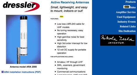 Active Receiving Antennas, designed for reception of shortwave, mediumwave and longwave signals and VHF/UHF signals
 -
 This article presents an innovative homebrew antenna design utilizing surplus ladder line as a receiving antenna for HF and MF bands. The Ladder Line Antenna (LLA) transforms standard 450-ohm ladder line into a directional, bidirectional, or omnidirectional antenna system through different termination methods. The design, which requires minimal space and height, achieves 6-10dB front-to-back ratio on 40-160m bands using a 33-foot length. This DIY wire antenna project offers an efficient, low-profile solution for amateur radio operators, featuring broadband operation without ground radials and easy installation below fence height.
 -
 This study details a reception comparison between vertical and horizontal active loop antennas, specifically two identical _Wellgood active loop antennas_, on various HF bands. The experiment, conducted in a densely populated QRM-prone area, monitored FT8 signals over a 24-hour period using two identical receivers. The methodology involved direct comparison of signal reception across the HF spectrum, aiming to identify performance differences based on antenna orientation. The results indicate that vertical loops demonstrated superior performance on higher bands (10m, 15m, 20m), while horizontal loops excelled on lower bands (30m, 40m, 160m), particularly for receiving long-distance (DX) signals. The horizontal loop's advantage on lower bands is attributed to potentially better low-angle performance and reduced sensitivity to man-made noise, yielding a **2-3 S-unit** improvement on 160m. The study provides practical insights for optimizing antenna placement in challenging urban environments, noting that the horizontal loop consistently showed a **10-15 dB** signal-to-noise ratio improvement on lower bands.
 -
 IAT is an excel sheet table evaluate parameters of VHF UHF antennas edited by Vladimir UR5EAZ. The difference between this tool and the existing VE7BQH Antenna Table is the use of G / T and C / N instead of the G / Ta parameter. In this table, Vladimir applies the ITU recommendations to assess the noise properties of a radio receiving system and shows the advantage of the G / T concept over the G / Ta concept when choosing an antenna.
 -
 The small receiving loop (SRL) is a versatile and efficient antenna that can be simply built from common materials. It is designed for reception on the MF and HF bands and may be put in a variety of shapes and sizes. Despite its unusual installation, the porch loop in this case operated admirably, producing several DX spots on the 40m band. The SRL can be a great option for people looking to boost their reception on the MF and LF bands.
 -
 The Aziloop DF-72 antenna system provides 72 K9AY headings and 36 loop axes, allowing for rapid switching in 60 ms. It integrates a switchable 18 dB preamp, a 4-step attenuator (0-18 dB), and four 7-pole preselection filters to optimize receiver performance. The K9AY load is adjustable from 250 Ohm to 950 Ohm in 50 Ohm increments, offering flexibility for various receiving conditions. Control is managed via an intuitive Windows UI, supporting Local, Client, or Server modes, with headless remote operation possible through the built-in Ethernet Server. _Omni-Rig_ support facilitates auto-filter selection, PTT muting, and Rig-Sync functionality, enhancing integration with existing station setups. Designed by _GW4GTE_, the system utilizes a low visual impact, small-footprint antenna with orthogonal loops and an earth connection. It is suitable for general monitoring, co-channel station resolution, basic direction finding, and interference reduction across the VLF to HF spectrum.
 -
 This resource details the construction and performance of a compact broadband magnetic loop antenna designed for portable receiving applications with devices like the _ATS MiniRadio_. The antenna utilizes approximately 3 meters of 0.5–1 mm copper wire wound in two turns on a rhomboidal wooden frame, measuring 50 cm by 70 cm. It connects via a modified 9:1 unun, where the primary center tap is isolated from ground to improve common-mode noise rejection. The design provides untuned operation across a frequency range from the longwave band up to approximately 25 MHz. Performance characteristics include observable directivity for noise suppression and the ability to connect directly to a radio or via a 50 coaxial cable for remote operation. The article specifies the unun's 3:1 turns ratio and its SMA output for connectivity. The methodology focuses on practical construction and observed reception quality.
 -
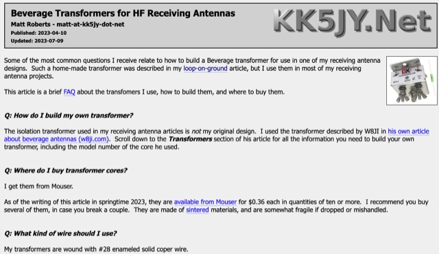 This FAQ covers building and buying transformers for loop-on-ground and Beverage antennas. Building one uses ferrite cores and thin wire. Buying is an option, with the DX Engineering BFS-1 being recommended. These transformers isolate the antenna from the cable to prevent unwanted signal pickup.