Search results
Query: homebrew power
Links: 52 | Categories: 1
-
 I built a homebrew 75 meter Double Extended Zepp Antenna, And I needed a 4:1 Balun So I decided to Homebrew the Balun also. Here is how I did it!
 -
 Amateur radio operators often seek reliable equipment for various modes and bands, from QRP operations to high-power DXing. Historically, Ten-Tec has been a notable manufacturer in the amateur radio market, known for its range of products including HF and VHF transceivers, RF amplifiers, and antenna analyzers. Their product line also encompassed specialized items such as QRP transceivers and kits, catering to enthusiasts of low-power communication, and antenna tuners for impedance matching. The company's offerings included test equipment vital for shack setup and maintenance, like SWR meters and RF analyzers, which assist in optimizing antenna systems and ensuring efficient power transfer. Additionally, Ten-Tec provided various accessories and components, supporting both commercial products and homebrew projects. The brand was recognized for its _made in the USA_ manufacturing, appealing to operators who prioritize domestic production. While the website currently displays limited product information, it mentions upcoming items like the _MODEL 594 PHOENIX_ and the _Tune-A-Tenna_, indicating potential future product releases.
 -
 The website https://www.qsl.net/dl5dbm showcases homebrew projects related to KW, 2-meter, 6-meter, antennas, amplifiers, preamps, power supplies, and more. It provides information and resources for radio amateurs interested in DIY projects and experimentation.
 -
 The project details a DIY SWR/Wattmeter designed around an _Arduino Uno_ shield, providing capabilities to measure RF power from 2 to **200 watts** and Standing Wave Ratio (SWR) for HF amateur radio bands. This construction features a compact design, integrating the measurement circuitry directly onto a custom PCB that interfaces with the Arduino Uno microcontroller. Key components include a directional coupler for sensing forward and reflected power, precision rectifiers, and analog-to-digital conversion for processing RF signals. The Arduino firmware handles calibration, calculations, and displays the results on an integrated LCD, offering real-time feedback on antenna system performance. The design prioritizes simplicity for homebrewers. Performance specifications indicate accurate readings within the **2-200W** power range, suitable for typical QRP to medium-power HF operations. The project provides schematics and a basic overview of the software logic.
 -
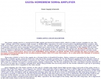
 3 elements VHF Yagi homebrew antenna designed with YAGIMAX 3. Maximum forward GAIN is about 8,17 DBi. This antenna offering an effective radiation power 4 times greater of the transceiver output by SV1BSX
 -
 This homebrew legal-limit antenna tuner is based on the famous "Ultimate Transmatch" introduced by the late Lew McCoy, W1ICP. The Ultimate Transmatch was described in the "Beginner and Novice" section of the July 1970 QST (Page 24).
 -
 The project details modifications to an ARK-40 QRP CW transceiver kit, specifically replacing its original thumbwheel frequency selectors with a **BASIC STAMP BS-II microcontroller** and an optical shaft encoder. The redesigned control circuitry outputs a BCD code to the ARK-40's synthesizer, enabling more convenient knob-type tuning. This modification significantly alters the user interface, moving from discrete frequency selection to continuous tuning. Operating frequency is presented on an LCD readout, offering two distinct display modes: a "bandspread dial" mode that simulates an analog dial scrolling across the display in 1 kHz increments, and a conventional digital readout with 100 Hz resolution. Pushing the main tuning knob toggles between these modes, providing both rapid band traversal and fine-tuning capabilities. The software for the BASIC Stamp is written in P-Basic, addressing the challenge of accurate analog dial simulation. Physical modifications include fabricating a custom PC Board for the STAMP, mounting it with an L-bracket to the optical encoder, and creating a new front panel. The front-mounted speaker was relocated to accommodate the new tuning knob and display, transforming the **ARK-40 transceiver** into a more user-friendly rig with its built-in CW keyer and 5 watts of power.
 -
 This homebrewed antenna tuning unit also incorporates a 50-ohm QRP dummy load, power meter (1 or 10 Watts full scale), and SWR meter
 -
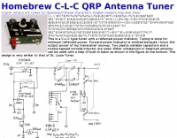 This is a C-L-C type tuner with a reflected power indicator. Tuning is done for minimum reflected power.
 -
 Details a practical QRP wattmeter construction, leveraging a simplified SWR meter design by JA6HIC. The project focuses on a forward-only power measurement circuit, providing a functional instrument for RF power levels from milliwatts up to 5 watts. It maintains a 50-ohm input and output impedance, suitable for typical QRP transceivers and antenna systems. The resource includes the schematic for the "VSW" (Very Simple Wattmeter) and outlines a six-step alignment procedure. This calibration process involves using a known RF source up to 5W, setting full-scale deflection, and marking power increments. It also addresses minimizing frequency effects on readings with a 100pF trimmer capacitor, noting that measurement error is highest at the lower end of the scale. Construction notes mention using a piece of RG-213 coaxial cable for the inductance and coupler, with the wattmeter assembled in early 2003. The author provides an example measurement showing 0.8W into a dummy load and 1W into a 3-element beam.
 -
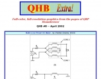 Build a Low Power 4:1 Balun , by Charles Greene, W1CG with full-color, full-resolution graphics from the pages of QRP Homebrewer
 -
 How to homebrew an hex beam antenna for 20 17 15 12 10 meters band by VA7ST
 -
 VU2RAR basic VHF power amplifier suitable for 144-146 Mhz output power can vary from 3 to 25 Watts.
 -
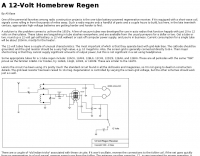 A one-tube battery-powered regenerative receiver.
 -
 Engaging in **QRP** operations, where amateur radio transceivers transmit at five watts or less, presents a unique challenge and satisfaction for many radio amateurs. This mode emphasizes efficient antenna systems, keen operating skills, and often, the art of **homebrewing** equipment to maximize performance under power constraints. Operators frequently utilize CW (Morse code) for its superior signal-to-noise ratio, enabling reliable contacts over long distances with minimal power. The VK QRP Club, formally known as the CW Operators' QRP Club Inc., serves as a focal point for Australian amateurs passionate about these low-power pursuits. The club fosters a community where members can share insights on antenna design, circuit construction, and operating techniques specific to QRP. It provides resources such as information on club nets and frequencies, Morse practice materials, and a platform for exchanging ideas among enthusiasts. Membership offers access to a network of like-minded individuals, promoting the continued development and enjoyment of QRP within the amateur radio hobby. The club's activities encourage experimentation and skill refinement, vital aspects of successful low-power communication.
 -
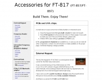 An external keypad for FT-817(ND), for the serious portable/field-day contester/operator. Homebrew it with the free firmware and public circuit diagram. The circuit is very simple and takes power supply from the ACC port of the radio
 -
 An RF power supply for 144 MHz schematics and instructions
 -
 VU3NSH article on high current universal supply for rigs
 -
 VHF UHF Amateur radio antenna and antenna parts, accessories for homebrewers, antenna kits, tubes, antenna masts, antenna tripores, insulators, power amplifier mosfet, power splitters by I0JXX
 -
 Home made RF power amplifier for six meter band
 -
 Whether we are tuning up homebrew equipment, checking antenna VSWR, adjusting a linear amplifier, or just monitoring output power during a contest, almost all aspects of ham operation can use a power meter. Paul Wade W1GHZ
 -
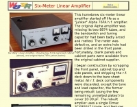 This homebrew six-meter linear amplifier started off life as a "junker" Alpha 76PA h.f. amplfier. Power output is 800W
 -
 The circuit is based on two AD8307 log amplifiers, which are connected to the forward and reflected ports on a directional coupler
 -
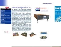
 Offer a wide range of homebrewing projects mainly for VHF UHF operations. From vhf antennas to preamplifiers, chargers and power supplies
 -
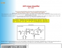 There is not a personal design on this page, just I've transfered useful notes from PHILIPS RF Bipolar Transistors - Data HandBook about BLY89C VHF Power transistor, which is very popular among Amateur Radio homebrewers
 -
 Balun case construction, tipically to host toroid cores. Size of case depends on power to handle. By DL5DBM
 -
 Amateur Radio Projects & Kits for homebrewers, includes DDS,sound card interface,programmers, hamcom, frequency counter, RF Power Meter, modems and more.
 -
 Homebrewed handheld RF powermeters for various sensors by DL5NEG
 -
 Presents a QRP AM/CW transmitter project specifically designed for the 10-meter band, utilizing a crystal oscillator and a collector-modulated AM oscillator. The design employs a 2N2219(A) transistor in a Colpitts configuration, generating 100 to 350 mW of RF output power depending on the 9-18 Volt supply voltage and modulation depth. Frequency stability is maintained by a 28 MHz crystal, with fine-tuning possible via a Ct1 trimmer capacitor for approximately 1 kHz adjustment. The resource details the RF oscillator stage, implemented with a 2N2219 NPN transistor, emphasizing frequency stability and low power dissipation. It also covers the amplitude modulation stage, managed by a 2N2905 PNP transistor, which impresses audio information onto the carrier. Selective components (C3, C4, C7, C5) enhance voice frequencies within a +/- 5 kHz bandwidth, and modulation depth is controlled by R2 and R3. The project includes a 3-element L-type narrow bandpass filter (Ct3, L3, C10) to suppress harmonics and ensure a clean output signal. The project provides a complete schematic diagram, a comprehensive parts list including specific capacitor, resistor, and inductor values, and construction notes for the coils (L1, L2, L3). It also offers practical advice on enclosure requirements, suggesting an all-metal case or a PVC box with graphite paint for RF shielding. Operational parameters such as current draw (27mA@9V to 45mA@16V) and input impedance (50 Ohms) are specified, alongside guidance on antenna matching and the importance of a valid amateur radio license for 10-meter band operation.
 -
 The resource details the construction of a homebrew 50-watt FET amplifier, based on Don W6JL's _QST Homebrew contest_-winning design from 2009. It functions as an afterburner for QRP transceivers, providing a **12dB** power lift. The amplifier utilizes IRFZ24N FETs and covers the 80, 40, 30, and 20-meter bands, with the 20m LPF extending to 17m. Key technical aspects include an FT37-43 transformer for the input network, a relay-switched 3dB pad for lower bands controlled by an _Arduino Nano_, and an RF-actuated T/R switch. The LPF board integrates four relay-switched filters rated for 50 watts, using capacitors with a minimum 250VDC rating. Performance measurements indicate a power gain ranging from **4.4dB** on 20m to 8.1dB on 80m, with a required drive power of approximately 5 watts. The article also discusses thermal management, current limiting considerations, and component sourcing.
 -
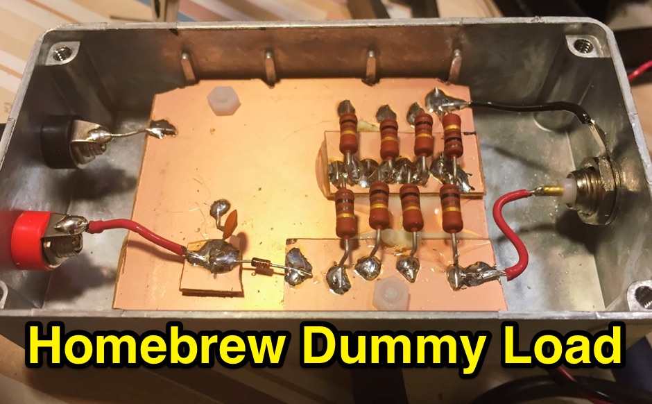 A simple 50 ohm dummy load to test transmitters. includes a simple RF diode detector to measure the peak voltage, and calculate the power
 -
 A system designed to automatically tune small transmitting magnetic loop antennas, particularly beneficial for **contest operations** where rapid frequency changes are common. The core of the system involves a PC-based control application, AutoCap, written in C#, which monitors antenna SWR via an external meter and commands a motor interface to adjust the loop's variable capacitor. The software is compatible with Windows and Linux via the Mono framework, offering a graphical user interface for monitoring system status, SWR, power, and motor commands. Key components include one or more magnetic loop antennas equipped with DC or stepper motors for capacitor adjustment, an SWR meter with data output (such as the Telepost LP-100A or a homebrew serial/USB SWR meter), the AutoCap PC software, and a motor interface. The most effective motor interface utilizes an **Arduino-based controller** with custom firmware, providing precise control over both simple DC motors and stepper motors, and supporting features like motor braking for finer adjustments. The system allows for configurable SWR thresholds, pulse widths, and motor effort settings to optimize tuning speed and resolution. Optional radio integration provides frequency hints, enabling the algorithm to learn the relationship between motor actions and resonant frequency, thereby speeding up initial tuning responses. The software also supports antenna profiles, allowing operators to save and recall specific configurations for different loops, including accumulated frequency hint data.
 -
 Presents the construction of a 2-meter **Skeleton Slot Yagi** stack, detailing the design process and practical considerations for VHF operation. The author shares insights from building and testing this antenna, emphasizing its performance characteristics for local and extended range contacts. The project outlines the specific dimensions and materials used, providing a clear path for other radio amateurs to replicate or adapt the design for their own stations. The resource covers the unique aspects of the Skeleton Slot radiator, explaining how its geometry contributes to gain and pattern control. It includes discussions on impedance matching and feedline considerations crucial for optimizing power transfer and minimizing SWR. The article draws on real-world testing, offering practical results that validate the theoretical design. This project serves as a valuable reference for those interested in custom VHF antenna solutions.
 -
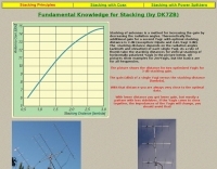 Stacking principles, with homebrew coax- and power-splitters by DK7ZB
 -
 A DIY Automatic Band Decoder (ABD) project, designed for dual-radio operation, addresses the common challenge of integrating band data with older transceivers lacking dedicated outputs. This particular build utilizes an AVR AT90S8515 microcontroller and a 16x2 Liquid Crystal Display (LCD) to provide band information, specifically targeting Kenwood rigs via a computer's LPT port. The design aims for cost-effectiveness while maintaining functionality, offering a solution for hams seeking to add automatic band switching capabilities to their station without significant expense. The project outlines the core components required, including the microcontroller, LCD, and an enclosure, noting that the Printed Circuit Board (PCB) fabrication and AVR programming might present challenges for some builders. It details the input requirements, such as a four-pin input and PTT for each radio, along with a 13.8V DC power supply. The decoder provides 2x6 outputs capable of sinking 500mA, suitable for controlling external devices like antenna switches or filters. Despite the original unit being damaged by a lightning strike in 2004, the author confirms its successful operation prior to the incident and mentions plans for a revised version. The resource includes a schematic in PDF format and images of the finished PCB and assembled unit, demonstrating the practical implementation of the design.
 -
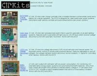 Solar power DIY kits. Homebrew your own solar power regulator, and power center.
 -
 This online project guide details the construction of a homebrew boom microphone system. It details the assembly of a microphone shell from a 3/4" PVC pipe section and an end cap, requiring a drilled hole for a snug fit of the electret or condenser mic element. The internal wiring schematic specifies a **2.2 K** resistor and a **47 uF** polar capacitor for signal conditioning, with a circuit diagram provided for integration with IC-706 series transceivers. The guide outlines the use of CAT-5 cable for internal connections, incorporating strain relief at the rear of the mic shell, and an inline 3.5 mm jack to facilitate an external _PTT_ line, designed for a foot-mounted switch. Further construction involves fabricating a microphone shock mount from a 2-inch PVC connector, detailing the creation of four "fingers" and the insertion of screw-eyes for attaching elastic bands, which are twisted 180 degrees for tensioning and vibration isolation. A foam wind screen is also incorporated into the microphone assembly, secured with adhesive. The boom arm itself is repurposed from an articulated architect lamp, with the original lamp assembly converted into a **60 watt** resistive load for testing power sources. Microphone cabling is secured to the boom arm using wire ties, ensuring sufficient slack at hinge points to maintain articulation. The boom base is mounted to a bookshelf, requiring specific positioning to achieve proper microphone placement in front of the operator. Performance evaluation of the microphone system is conducted through on-air audio signal reports from other amateur radio operators. DXZone Focus: Online Project Guide | Boom Microphone Construction | Electret Mic Element | PTT Line
 -
 Announces the retirement of Brand Electronics, a manufacturer specializing in **power meters** and various ham radio accessories, effective 2025. The company has served the amateur radio community for over 35 years, providing equipment for station setup and operation. The product line historically included accessories compatible with major transceivers from Icom, Yaesu, and Kenwood, alongside components and technical references for homebrew projects. Their offerings supported accurate RF power measurement, crucial for optimizing antenna systems and ensuring legal limit compliance. This notice serves as a final update regarding the company's operational status, marking the cessation of manufacturing and sales activities. The site provides no further details on product support or inventory liquidation.
 -
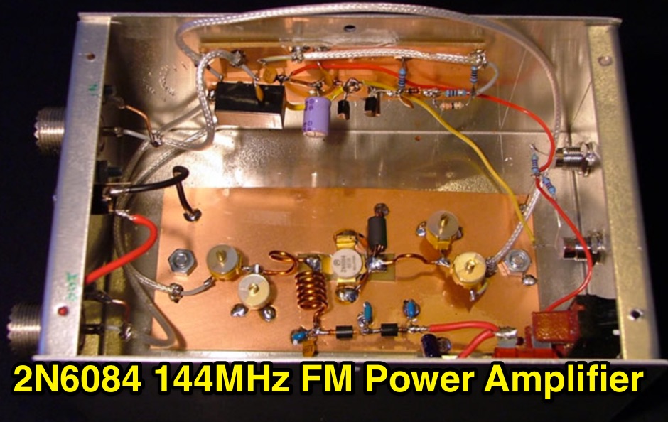 A 144MHz FM class C RF Power Amplifier based on a 2N6084 RF transistor, that can produce 50w output max
 -
 Station QRP presents various **circuit diagrams** for constructing low-power AM vacuum tube shortwave transmitters, catering to enthusiasts interested in vintage radio technology. The resource details schematics ranging from simple to more complex designs, enabling hams to build their own QRP AM transmitters for operation on frequencies like 6.925 kHz AM. It emphasizes the use of vacuum tubes, providing a technical foundation for understanding and replicating classic shortwave broadcasting methods. The content is geared towards those who enjoy the hands-on aspect of electronics and the unique characteristics of tube-based RF circuits. Building these transmitters allows operators to experience the nostalgia of early shortwave radio, with the site specifically mentioning a pioneer station on 6.925 kHz AM. The designs facilitate experimentation with low-power AM transmission, offering practical application for homebrew projects. The focus on QRP (low power) operation aligns with a segment of the amateur radio community that values efficiency and minimalist setups, providing a distinct alternative to modern solid-state transceivers.
 -
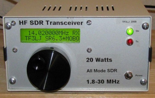 This project describes a DIY all band HF SDR transceiver. Built around a Softrock 6.3 kit, it boasts a 20W homebrew amplifier and ATmega168 microcontroller for USB control. An LCD displays frequency, power, and SWR. Automatic LPF selection and SWR protection enhance functionality. Compatible with Rocky and PowerSDR software, this project provides a cost-effective and powerful HF SDR transceiver for hobbyists.
 -
 Operating in a Single Operator Two Radios (SO2R) setup, especially with beverage antennas, often exposes the receiving radio's front-end to significant RF energy from the transmitting radio. This resource details a practical, homebrew receiver protection circuit designed to mitigate this risk. The core of the design involves a non-inductive 2W 22 Ohm carbon composition resistor in series with the RX antenna line, followed by two stacks of four fast-switching diodes (e.g., _1N914_) configured in opposite polarizations. This arrangement effectively clamps the incoming voltage to approximately 2.8 V peak-to-peak, safeguarding sensitive receiver input components. The series resistor plays a crucial role by absorbing excess power, preventing the diodes from exceeding their current ratings and potentially failing open, which would leave the receiver unprotected. The author, _N4KG_, measured up to 50 watts of coupled power between 80M slopers on the same tower, highlighting the necessity of such protection. The design is presented as a cost-effective solution to prevent damage to receiver input transformers, with the author noting successful protection of a receiver even after a resistor showed signs of overheating. This simple circuit can be integrated via a transverter plug, offering a robust defense against high RF input.
 -
 Presents various amateur radio topics through blog posts, detailing operational experiences and technical insights from the perspective of SV2YC. The content frequently discusses antenna projects, such as a **portable 20m/40m dipole** designed for rapid deployment, and explores the performance characteristics of different wire configurations in varied field conditions. Observations on propagation and band activity across the HF spectrum are also regularly documented, providing practical context for fellow operators. Specific entries often include detailed accounts of **DX contacts** and participation in minor contests, outlining station setup, power levels, and antenna choices. The blog also covers modifications to commercial transceivers and homebrew accessory construction, offering practical advice on improving station efficiency and functionality. Further posts delve into software applications for logging and digital modes, sharing configurations and operational tips for maximizing their utility in daily amateur radio activities.
 -
 This will show you how to add a RF power amplifier to your Proxim Symphony for under $50. The cost is reduced by using the existing components on the Symphony, such as the PIN diode switch, and just inserting a higher power final amplifier. Increase the RF output power of your wireless network card to 1 Watt.
 -
 The 222 MHz Transverter project, based on Zack Lau's (W1VT) original July 1993 QEX magazine design, provides an IF of 28 MHz for both transmit and receive paths. Rick Bandla (VE3CVG) contributed supplemental notes and construction details, including modifications to achieve 10 mW output power from an initial 4 mW PEP. The design incorporates three distinct boards: a Local Oscillator (LO), a Transmitter (Tx), and a Receiver (Rx), with an estimated parts cost of just over $150 CDN, significantly less than commercial kits. Construction involves both through-hole and surface-mount components, with specific guidance on mounting MAV and MAR devices, grounding techniques, and component selection. The project details include parts lists, schematics for the LO, Tx, and Rx, and board layouts. Troubleshooting advice emphasizes sequential testing, starting with the LO, then Tx, and finally Rx, using a 194 MHz and 222.100 MHz capable FM handheld for signal tracing. Further enhancements are discussed, such as an optional Tx driver stage to boost output to 100 mW and the potential modification of a Motorola Maxor 80 PA for 222 MHz SSB/CW operation. The resource also covers practical aspects like power attenuation pads for IF radios (e.g., FT817) and considerations for enclosure design, including repurposing a Maxor 80 case. Performance reports indicate successful 70 km contacts with only 4 mW output.
 -
 A picture gallery of a home-brew RF Power amplifier made with 3CX3000
 -
 This document outlines the construction of a homebrew Buddipole antenna variant, designed for portable use and emergency services. The antenna utilizes telescoping whips and loading coils, enhancing its versatility across various HF bands. Key components include fiberglass rods, brass fittings, and Anderson Power Pole connectors, ensuring robust electrical connections. The design emphasizes non-inductive materials to minimize interference, while practical assembly techniques, such as epoxy and heat shrink tubing, are employed for durability. This variant aims to improve upon traditional Buddipole designs, offering greater strength and functionality.
 -
 The FT101ZD DDS VFO project replaces the original VFO in the Yaesu FT101Z/ZD rigs with an AD9850 DDS module, providing enhanced frequency control. It uses the original optical encoder and clarifier for compatibility, with a custom 6V power supply modification. The project includes selectable step sizes, a frequency save function, and works with both RX and TX modes. The design involves mechanical and electronic modifications, including SMD components and a custom PIC processor. Calibration ensures accurate frequency output, with further improvements under consideration.
 -
 Tubes are a dying technology. All modern transmitters, even high power ones, do work with transistors and other semiconductors. But many fondly remember their first homebrew transmitter and its hard to forget warm glow of a vacuum tube. The Station QRP website is especially for you to come into touch with tube technology. This site is all about handcrafted QRP AM tube transmitters.
 -
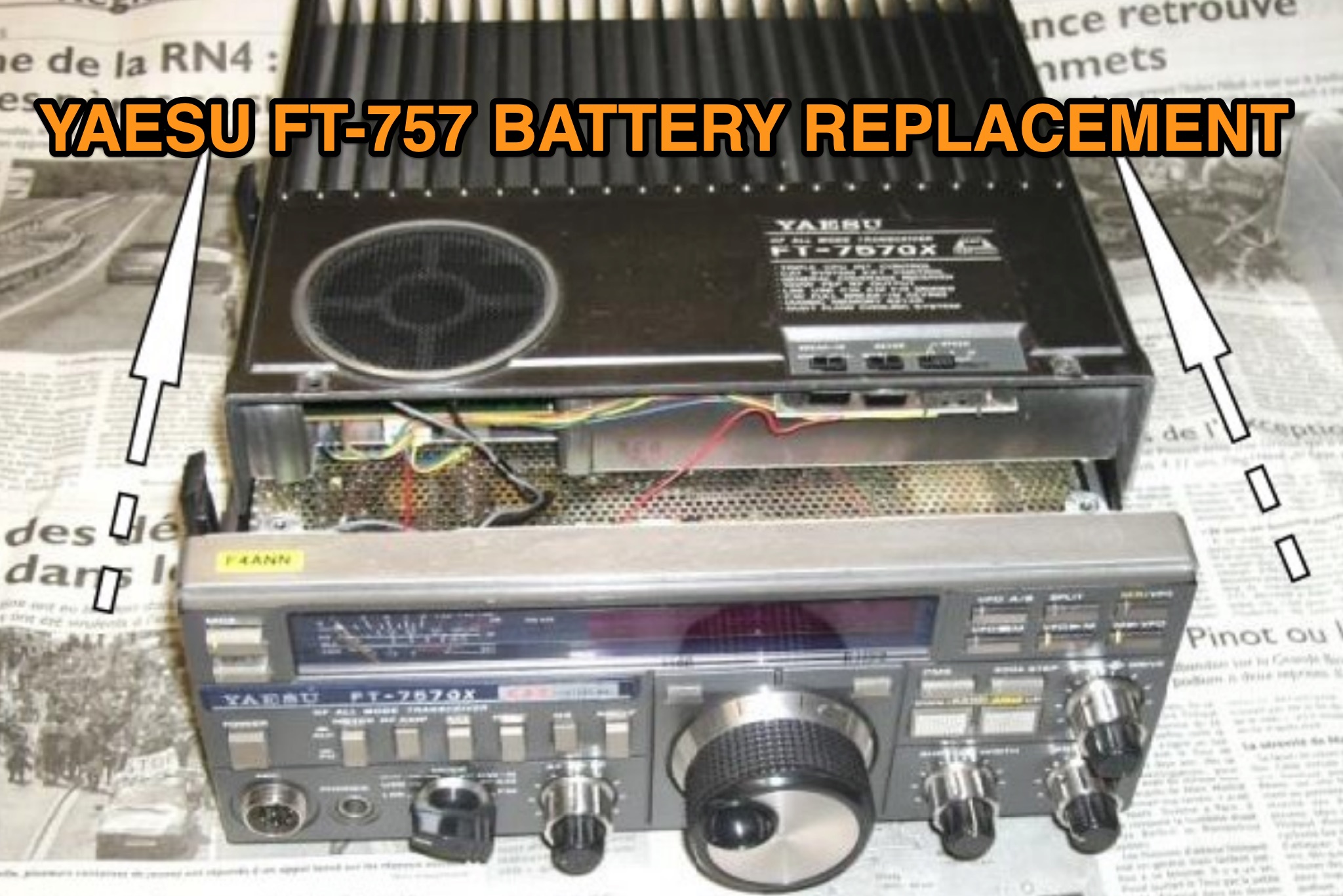 This guide by F4ANN (2014) explains replacing the backup battery in a YAESU FT-757 GX when stored frequencies reset on power-up. The original CR-1/3N lithium cell (3V, 160 mA) can be substituted with a CR2032 (170 mA), which is cheaper, widely available, and easier to replace. The process involves opening the transceiver, carefully desoldering the old battery from the PCB, and wiring in a holder for the CR2032. Extra care is required with screws, connectors, and soldering. The author also replaced backlights and serviced the cooling fan. Future battery replacements are simplified to four screws.