Search results
Query: ic 7200
Links: 4 | Categories: 0
-
 Demonstrates the construction of **magnetic loop antennas**, detailing both multi-turn and single-turn designs. It covers a 30-inch diameter multi-turn loop for 80 meters, based on a February 1996 QST article, and an octagon single-turn loop made from 15mm copper tube with a 4.8-meter circumference, operating from 7 MHz to 14 MHz. The document also presents a smaller 800mm diameter loop for 14 MHz to 28 MHz, emphasizing the importance of high-voltage tuning capacitors. Covers the design and construction of custom **butterfly capacitors** and piston capacitors, including a split stator capacitor with 140 pF capacitance and a 6000 Volt rating, and a butterfly capacitor with 5-65 pF and 7200 Volt rating. It explains why butterfly capacitors are preferred over split stator types for high power applications due to lower losses and direct series connection of rotors, reducing resistive losses from wiper contacts. Material recommendations include clear PVC for plates and brass or stainless steel for non-magnetic hardware. Addresses practical considerations such as feeding the loop with a shielded 1/5 Faraday loop made from RG213 or RG8 coax, achieving VSWR 1.1 across bands, and optimizing its placement 180° from the capacitor. It also discusses mechanical joint resistance, dissimilar metal oxidation prevention using Vaseline, and a simple method for determining radiation angle with a TL-light tube. The guide includes diagrams for rotor, stator, and end plate construction.
 -
 The NCDXF/IARU International Beacon Project schedule provides precise transmission start times for 18 beacons operating on 14.100 MHz, 18.110 MHz, 21.150 MHz, 24.930 MHz, and 28.200 MHz. Each beacon transmits every three minutes, cycling through its callsign at 22 WPM followed by four one-second dashes. The initial callsign and first dash are sent at 100 watts, with subsequent dashes at 10 watts, 1 watt, and 100 milliwatts, enabling **propagation analysis** across varying signal strengths. The schedule lists the minute and second within each hour for the first transmission of each beacon on its respective frequencies. This resource allows **DXers** and **contesters** to accurately predict beacon transmissions for real-time propagation assessment. For example, 4U1UN transmits first at 00:00 on 14.100 MHz, followed by VE8AT at 00:10, and W6WX at 00:20, continuing the sequence. The page also notes recent hardware upgrades, such as the installation of IBP 2.0 controllers with Icom 7200 radios at some sites, and provides status updates for beacons experiencing hardware failures or those not recently heard, aiding in troubleshooting and managing expectations for monitoring.
 -
 The NCDXF/IARU International Beacon Project operates a worldwide network of 18 high-frequency radio beacons, continuously transmitting on 14.100, 18.110, 21.150, 24.930, and 28.200 MHz. These beacons, initially launched in 1979 with a single station and expanded to the current 18-beacon system in 1995, provide reliable signals for both amateur and commercial users to assess current **ionospheric propagation** conditions. The system's design, construction, and operation are managed by volunteers, covering hardware and shipping costs. The resource details the evolution of the beacon network, including the transition from Kenwood TS-50s transmitters to Icom IC-7200 radios with a new controller design implemented in 2015. It explains how listening for these 100-watt signals, transmitted to vertical antennas, allows operators to determine band openings and optimal propagation paths globally. The content also references three QST articles providing historical context and technical specifics of the beacon project. Practical information includes methods for identifying transmitting beacons via a schedule or specialized software like FAROS and Skimmer, which integrates with the **Reverse Beacon Network** for automated monitoring.
 -
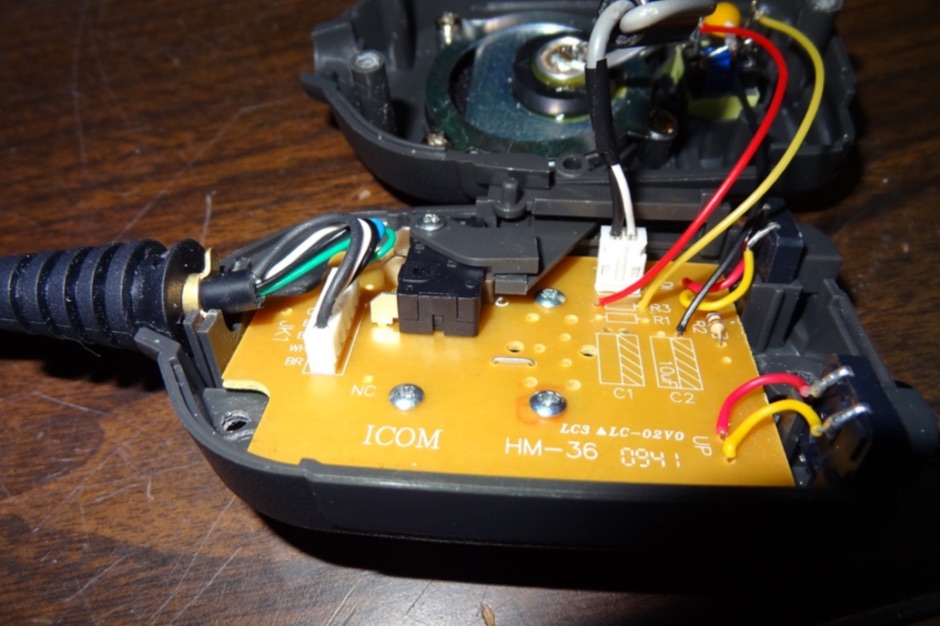 HM-36 Modification to make it work with an IC-7200 and the IC-7600