Search results
Query: ic 7700
Links: 12 | Categories: 1
-
 Official Icom comparison chart for IC 756 PRO III, IC-7600, IC-7700 and IC-7800
 -
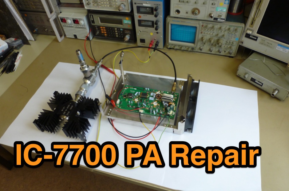 A well documented PDF document containing picture sequence taked during the repair of an Icom IC-7700 HF transceiver power amplifier module
 -
 KK5DR review of the IC-7700 HF ICOM Transceiver
 -
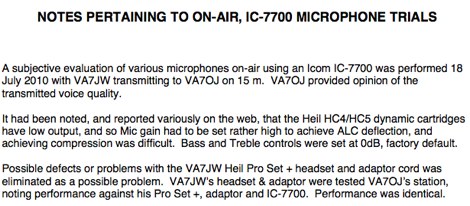 Evaluation of various microphones on-air using an Icom IC-7700 by VA7JW
 -
 The Icom IC-7600 compared to other Icom HF radios , like IC-756Pro III, IC-7700 and IC-7800 by VA7OJ/AB4OJ
 -
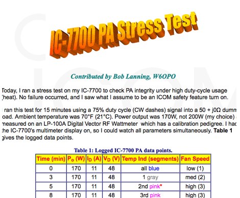 W6OPO report on Icom IC-7700 stress test to verify PA integrity under high duty-cycle usage
 -
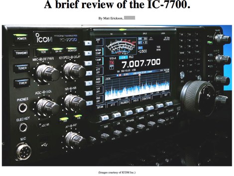
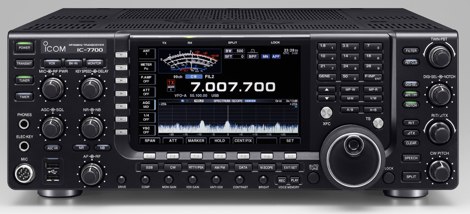 Exaustive review of the self-contained, top-performance HF/6m transceiver Icom IC-7700
 -
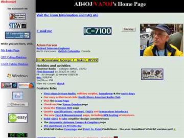
 A detailed review of the Icom IC-7700 by VA7OJ/AB4OJ
 -
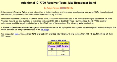 Testing the Icom IC-7700 on the mediumwave broadcast reception by VA7OJ
 -
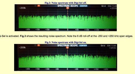
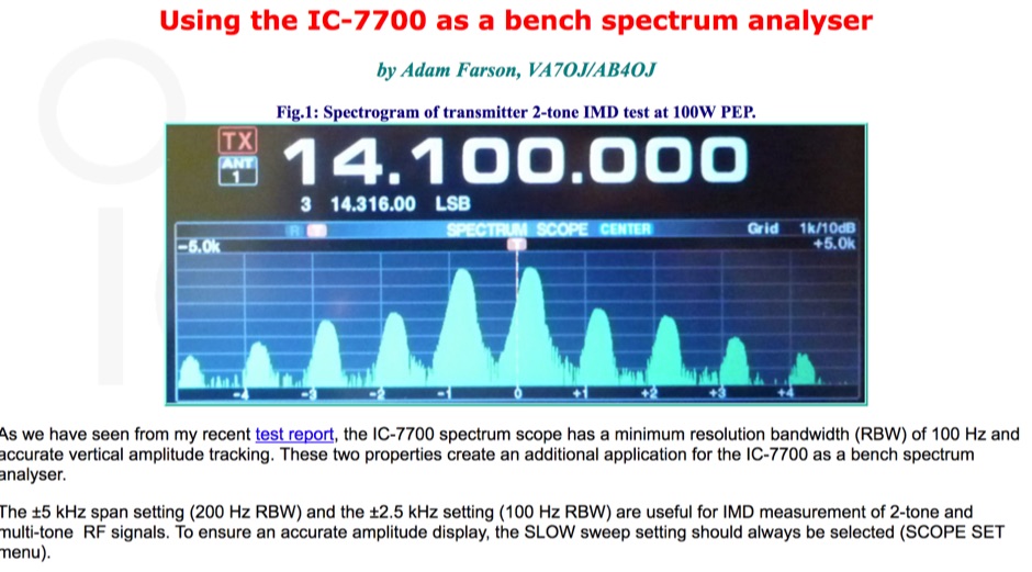 The Icom IC-7700 spectrum scope feature a minimum resolution bandwidth of just 100 Hz and provide also an accurate vertical amplitude tracking permitting to use the 7700 as a bench spectrum analyser.
 -
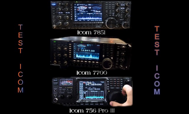 Reception test comparison between IC 756 pro III, IC 7700 and the last jewel by ICOM IC 7851
 -
 An Arduino-based interface provides a remote tuner call command for Icom **IC7700** and **IC7800** transceivers, addressing the lack of a built-in function for external tuners such as the MFJ 998RT. This setup initiates a low-power transmit signal, typically 15 watts, allowing the remote autotuner to perform its matching sequence. The article details the required CI-V line communication and modifications to existing Arduino code, specifically referencing contributions from Jean-Jacques ON7EQ for improved Icom interrogation routines. The system involves a sequence of steps: storing the transceiver's current mode and power, disabling the internal autotuner, activating a control relay to interrupt the amplifier line, switching to RTTY mode at low power, and initiating transmit. The transmit duration is manually controlled by the operator, observing the SWR meter until a low SWR is achieved, then a second button press stops the transmission. A built-in 4-second transmit limit provides a safety measure. After tuning, the routine restores the original mode and power settings, re-enables the internal autotuner, and performs a brief 2-second RTTY transmission for internal tuner adjustment. The circuit diagram includes a Panasonic form 2 relay for amp control and emphasizes critical delays in the Arduino code for stable operation at 9600 baud CI-V communication. Compatibility with logging software like DXLab, N1MM, and N3FJP is noted, with specific interrogation time settings required to avoid conflicts.