Search results
Query: lf receiver
Links: 28 | Categories: 0
-
 SysLabs RadioControl is a software platform for radio device control and application development. It operates on _Windows_ versions from Windows 95 and Windows NT 4.0 through _Windows 11_. The software is available in Lite, Standard, and Professional editions, each including Frontpanel for direct radio control, a Frequency Database for management, and a Memory File for channel operations. Features include frequency identification, memory scanning, and graphical spectrum views with bitmap export capability. The Professional Edition supports multi-device control and utilizes radio device-internal scanners, achieving scan rates of **40-60 steps per second** compared to the RadioControl-internal scanner's **10-20 steps per second**. Supported devices for internal scanning include AOR AR-5000, AR-8200, AR-8600, AR-ONE, R&S EB200, and various Icom receivers and transceivers. RadioControl supports older devices such as ICOM IC-R71, IC-R7000, IC-706, IC-735, YAESU FRG-8800, and FRG-9600, extending their control capabilities. The platform offers APIs for integration and supports import/export with formats from VisualRadio, SCANcontrol, shoc Radio Manager, WiNRADiO, AOR ACEPAC-3A, as well as generic Text, CSV, and HTML. DXZone Focus: Radio Control | Windows | Frequency Management | API
 -
 Hear VLF audio from NASA online VLF radio receiver in Huntsville, Alabama.
 -
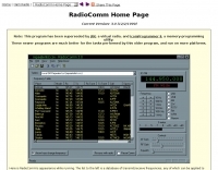 Demonstrates RadioComm, a freeware Icom transceiver/receiver controller program for Windows, which facilitates memory programming, spectrum analysis, and interfacing with extensive frequency databases. The software allows users to program their Icom radio's memory, generate radio-frequency spectra, and connect the radio to a computer-based frequency database. It supports various Icom models, offering bidirectional control where virtual controls mirror the transceiver's physical controls and vice versa. The program's spectrum analysis feature, exemplified by tuning the WWV time standard at 15 MHz, provides insights into the AM passband, a capability often found in high-end Icom transceivers. While RadioComm offers these functionalities, the author, Paul Lutus, notes that it has been superseded by JRX (a virtual radio) and IcomProgrammer II (a memory programming utility), which are described as superior and compatible with more platforms. RadioComm is available as a 516 KB self-extracting executable, requiring an Icom CT-17 RS-232 interface box for radios that need it. Users can also customize the plain-text database to include unsupported Icom models. However, the author explicitly states that no user support is provided for this free program.
 -
 End-Fed antennas are NOT balanced systems; but neither are verticals, ground planes, discones, windoms, zepps, Marconis, half-slopers, et al. Additionally, the low-impedance antenna port of your transmitter/receiver is not balanced.
 -
 Over 30 distinct shortwave (SW) receiver models are reviewed, offering insights into their performance, features, and user experiences. These evaluations, contributed by readers of the Usenet newsgroup **Rec.radio.shortwave**, cover a wide array of portable and tabletop radios, including popular units like the Grundig YB-400, Sony ICF-SW77, and various Realistic DX series models. Each review details aspects such as frequency range, tuning steps, SSB functionality, antenna performance, and construction quality, often comparing them to other receivers or ham transceivers like the Icom 725. For instance, the Grundig YB-400 review highlights its 144-30000 kHz AM/SSB coverage, direct keypad entry, and 40 station memories, noting its useful narrow bandwidth and tone switch for adjacent signal separation. It also discusses the **SSB mode** stability and the limitations of its 1 kHz frequency resolution for precise zero-beating. The review further details antenna performance, including the effectiveness of the built-in whip, the provided 7m reel antenna, and the potential for overload with larger outdoor antennas. Other reviews delve into specific issues, such as the Sony ICF-SW77's frequency display inaccuracies and timer malfunctions, or the Realistic DX-342's compact size and surprisingly good MW DXing capabilities despite its analog tuning. The collection provides practical, user-generated feedback on sensitivity, selectivity, audio quality, and ergonomic features, helping shortwave listeners understand the real-world performance and quirks of these receivers.
 -
 Constructing a Lindenblad antenna for 137MHz NOAA satellite reception involves specific design considerations for optimal performance. The resource details the use of 4mm galvanised steel fencing wire, 300-ohm television ribbon cable, and wood/plastic components for the antenna structure. Key dimensions for a 137.58MHz-resonant antenna are provided, derived from the ARRL Satellite Handbook, specifying s, l, w, and d as 42, 926, 893, and 654mm respectively. The antenna is designed for Right Hand Circularly Polarised (RHCP) signals, requiring the four folded dipole elements to be tilted clockwise by 30 degrees. A significant aspect covered is impedance matching between the antenna's 75-ohm impedance and a typical 50-ohm receiver input. A twelfth-wave matching transformer, constructed from 117mm sections of 50-ohm RG-58 and 75-ohm RG-59 coax with a 0.66 velocity factor, is described. The article also addresses coaxial cable and connector selection, recommending 75-ohm Type-N connectors for RG-6 cable in professional setups and F56/F59 connectors for general use, while strongly advising against PL-259/SO-259 connectors for VHF. Strategies for mitigating Radio Frequency Interference (RFI) are discussed, including antenna placement to shield from local TV transmitters and the use of commercial or DIY band-pass filters, such as cavity resonators or helical notch filters, along with ferrite chokes on coaxial cables. Antenna orientation is explored, noting the Lindenblad's 'cone of silence' directly overhead and its maximized sensitivity towards the horizon. An experimental vertical tilt of 90 degrees is presented as a method to improve overhead reception and reduce interference from strong horizontal signals, particularly relevant in high RFI environments like the Siding Spring Observatory site.
 -
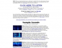
 A page about fascinating Very Low Frequency and natural radio, with lots of streaming audio links from remote receivers. Some experimental stereo pairs around the world.
 -
 Examines the historical landscape of "boat anchor" amateur radio equipment manufacturers, focusing on the technical innovations and market dynamics that shaped the industry from the pre-WWII era through the transition to SSB. It details the origins and key product lines of prominent U.S. companies like _Collins Radio Company_, _Central Electronics_, and _Barker & Williamson_, highlighting their contributions to receiver and transmitter design. The resource contrasts early AM technology with the advent of SSB, explaining the circuit changes required in receivers and the complete rethinking needed for transmitters. It discusses the impact of military contracts on company survival and the eventual shift towards smaller, self-contained transceivers. Specific examples, such as the _Collins R-390/URR_ receiver and the _Central Electronics 100V/200V_ broadband transmitters, illustrate the engineering prowess and design philosophies of the era, offering insights into their operational characteristics and enduring appeal among collectors.
 -
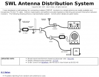 a methodology for connecting multiple LF/MF/HF receivers to a single antenna via readily available and inexpensive 75-ohm TV cable.
 -
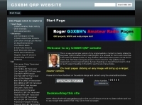 Roger, G3XBM, shares his extensive experience in **QRP** (low-power) amateur radio operation, detailing various aspects of transmitting with minimal power. The resource provides insights into VLF (Very Low Frequency) reception techniques and the construction of simple **crystal radio sets**, reflecting a foundational approach to radio experimentation. It includes links to external resources covering QRP clubs, online receivers, manufacturers, and technical references, offering a curated collection for enthusiasts. His page serves as a hub for those interested in the challenges and rewards of QRP, often comparing the efficacy of different low-power setups. The practical application extends to understanding basic radio principles through hands-on projects like crystal sets, which G3XBM has explored. The collected links provide a starting point for further research into specific QRP equipment or operating practices, drawing on G3XBM's long-standing engagement with the QRP community.
 -
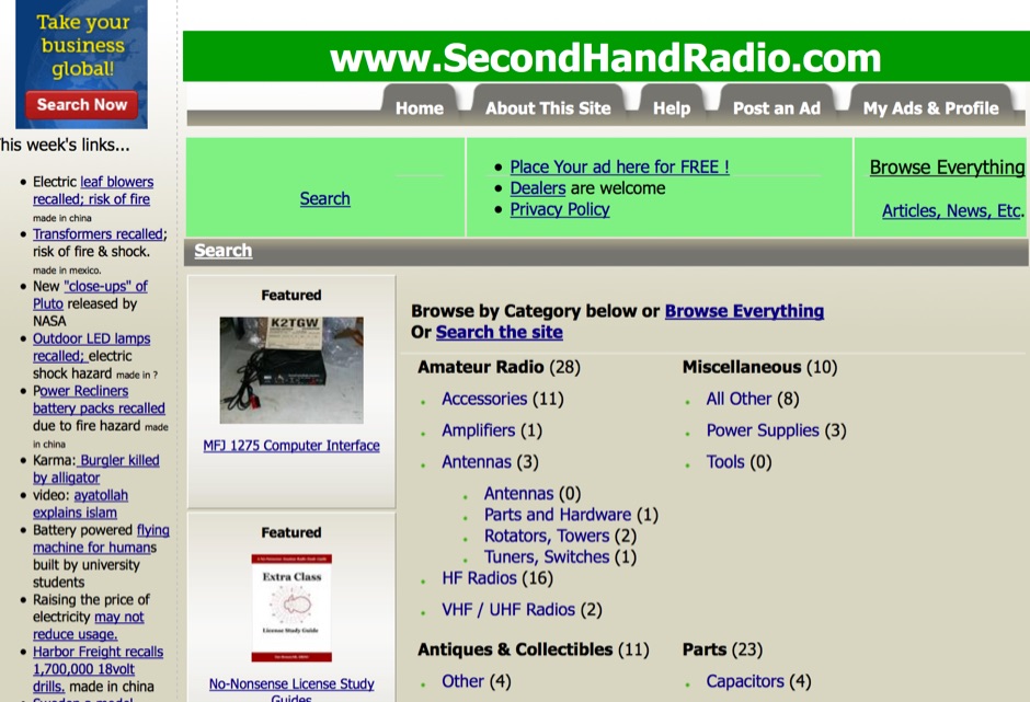 SecondHandRadio.com provides a platform for the amateur radio community to buy, sell, and swap used, surplus, and obsolete electronics and electrical equipment. The site facilitates transactions for a wide range of items, including ham radio transceivers, test equipment, shortwave receivers, antennas, and vintage radio components like tubes. Users can place classified advertisements with photos at no cost, catering to individuals, radio clubs, and commercial dealers seeking to liquidate or acquire gear. The platform emphasizes ease of use with a straightforward sign-up process and no associated fees or commissions for listing or selling items. It positions itself as a primary resource for used electronics within the USA, fostering a direct connection between sellers and buyers without intermediary charges. The service supports various categories beyond amateur radio, extending to military radios and antique equipment, thus serving a broad spectrum of radio enthusiasts and collectors.
 -
 Operating on the 2200m band (135.7-137.8 kHz) often presents challenges for amateur radio transceivers, which typically exhibit poor receiver performance at these very low frequencies. This project addresses the issue by providing a design for a dedicated 137 kHz antenna preamplifier, specifically tailored to improve signal reception for radios such as the _Yaesu FT-817_. The preamplifier circuit utilizes a low-noise FET input stage, crucial for minimizing self-generated noise and maximizing the signal-to-noise ratio from weak LF signals. The design includes a detailed schematic, component values, and construction notes, enabling homebrewers to build a functional unit. The goal is to achieve significant gain, making the faint signals on 2200m more discernible and improving overall band usability. Key design considerations include impedance matching to typical antenna systems and ensuring stable operation across the narrow LF segment. The circuit aims for a **low noise figure** and sufficient amplification to overcome the inherent limitations of general-purpose HF transceivers when operating below **200 kHz**.
 -
 Over two decades ago, the Kenwood TS-850S HF transceiver established itself as a robust performer, known for its excellent receiver and versatile operating features. This vintage rig, often found on the used market, continues to be a favorite among many amateur radio operators for its solid construction and reliable performance across the HF bands. Adrian's Yahoo! Group provided a dedicated forum for TS-850S owners to exchange insights, troubleshoot issues, and share modifications or operational tips. Such community-driven platforms were crucial for extending the operational life and maximizing the utility of classic transceivers, fostering a spirit of mutual aid among hams. Discussions frequently covered topics like DSP unit upgrades, common repair challenges, and optimizing the rig for contesting or DXing, reflecting the enduring interest in this particular Kenwood model.
 -
 Showcasing a specialized product line, Advanced Receiver Research presents a comprehensive catalog of **low noise preamplifiers** and microwave **Gunnplexers**. The offerings span a broad spectrum of radio frequencies, from VLF, LF, MF, and HF bands up through VHF, UHF, and microwave, catering to diverse applications including amateur radio, commercial installations, and military systems. Their product range includes mast-mount preamplifiers, inline attenuators, power dividers, and various coaxial components. My own experience with similar low-noise front ends for weak-signal work on 2 meters and 70 centimeters underscores the critical role such components play in maximizing receiver sensitivity, especially when chasing distant DX or engaging in EME. The detailed product descriptions and technical specifications provided on the site allow operators to select the optimal preamplifier for their specific band and noise figure requirements, essential for improving signal-to-noise ratio. The site also lists specialized products for unique applications like Nuclear Magnetic Resonance (NMR) and Studio Transmitter Links (STL), demonstrating a depth of engineering capability beyond typical amateur radio fare. This breadth of offerings, coupled with clear ordering and warranty information, positions Advanced Receiver Research as a key supplier for high-performance RF components.
 -
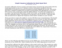 Accurate calibration of your receiver and sound card is necessary for good results with the weak signal modes in use at LF. Modern receivers with master oscillators that are synthesized to provide all conversion frequencies greatly simplify the process. This article describes a method of making the necessary measurements and adjustments to an ICOM R75 receiver and a sound card, using the ARGO software
 -
 Using a PC with soundcard as a VLF receiver, how to use your PC as a receiver for narrow-band signals in the VLF radio spectrum by DL4YHF
 -
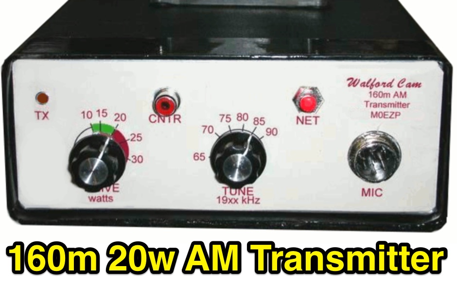 Born as a companion transmitter for the Yaesu FRG-7 receiver has become a stand alone tramsmitter for 160 meters band
 -
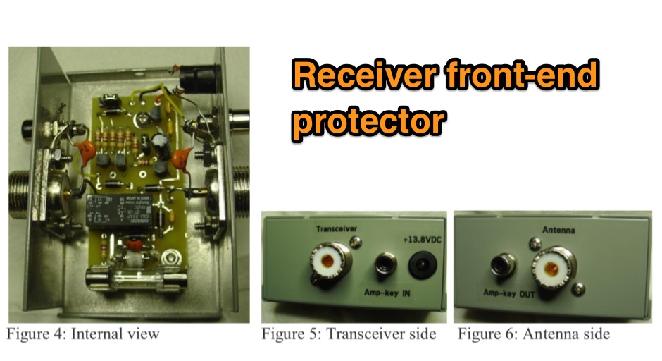 A transceiver front-end protector in high signal level environments. An homemade RF limiter to protect your receiver front-end from high radio frequency.
 -
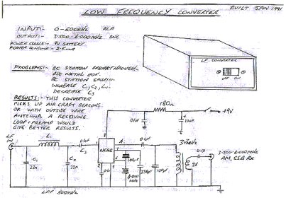 This converter uses the popular NE602 mixer/oscillator chip and allows reception of signals below 500 kHz on a 3.5 – 4 MHz HF receiver
 -
 IK2PII describe here a simple direct conversion receiver, thinked for QRSS and DFCW communications, as companion of ARGO or SPECTRAN programs.
 -
 A cavity filter, often a critical component in _duplexer_ designs, functions as a sharply tuned resonant circuit, allowing only specific frequencies to pass while attenuating others. These filters are essential for maintaining signal integrity in environments where multiple transmitters and receivers operate simultaneously on closely spaced frequencies, such as in repeater stations. The article details how these filters, sometimes referred to as _notch filters_, achieve high Q factors, which are crucial for their performance. Understanding the principles of cavity filters is fundamental for any amateur radio operator involved in repeater operation or designing custom RF front-ends. The discussion covers the basic circuitry and operational characteristics that enable these devices to provide significant isolation, often achieving **-80 dB** or more between transmit and receive paths. This level of isolation is vital for preventing receiver desensitization and intermodulation distortion. Properly tuned cavity filters ensure that a repeater can transmit and receive simultaneously on different frequencies without self-interference, a common challenge in VHF/UHF operations.
 -
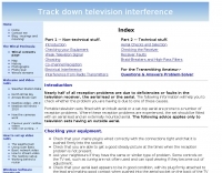 Nearly half of all reception problems are due to deficiencies or faults in the television receiver, the aerial lead or the aerial. This article will help you to check whether the problem you are having is due to one of these causes.
 -
 Presented is a historical collection of short-wave listening (SWL) QSL cards, primarily from the late 1930s and early 1940s, offering a glimpse into early international broadcasting and the technical pursuits of SWL operators like Les Miles during that era. The resource showcases specific QSLs from stations such as _Broadcasting Corporation of Japan_, _XGOY - The Central Broadcasting Administration_ in Chungking, China, and _Australian broadcasting ship, Kanimbla VK9MI_, each with reception dates and frequencies like 11.90MHz or 9.525MHz. It highlights the self-sufficiency of SWL enthusiasts who constructed and maintained their own radio and test equipment, evoking the sensory experience of vintage valve receivers. The collection provides concrete examples of international broadcast stations active before and during World War II, including _2RO3 - Rome_ and _WRUL - World Wide Broadcasting Foundation_ from Boston. Each QSL entry details the station, location, reception date, and often the frequency, such as 9.63MHz or 11.26MHz, allowing for historical verification of broadcast schedules. The resource also briefly mentions the operational details of the _VK9MI_ offshore radio station, directing readers to further information on its history. This compilation serves as a tangible record of global radio communication during a pivotal historical period.
 -
 Low-frequency (LF) radio time signals, operating primarily in the 40–80 kHz range, are broadcast by national physics laboratories for precise clock synchronization. Transmitters like **JJY** (40 kHz, 50 kW; 60 kHz, 50 kW), RTZ (50 kHz, 10 kW ERP), MSF (60 kHz, 15 kW ERP), WWVB (60 kHz, 50 kW ERP), RBU (66.66 kHz, 10 kW), and DCF77 (77.5 kHz, 50 kW) cover vast geographic areas, often several hundred to thousands of kilometers. LF signals offer distinct propagation advantages over higher-band transmissions such as GPS. Their long wavelengths (3–6 km) enable effective diffraction around obstacles like mountains and buildings. The ionosphere and ground act as a waveguide, eliminating the need for line-of-sight and allowing a single powerful station to cover extensive regions. Ground wave propagation minimizes ionospheric variability effects on transmission delay, and signals penetrate most building walls effectively. Robust and low-cost receivers, often priced at 20–30 USD/EUR, are widely used in radio clocks. These receivers typically comprise a tuned ferrite core antenna, a receiver IC (e.g., Atmel T4227, U4223B, MAS1016) for amplification and AM detection, and a microcontroller for decoding the time signal and phase-locking a local clock. Specific components for DCF77, MSF, and WWVB are readily available from vendors like HKW Elektronik and Ultralink.
 -
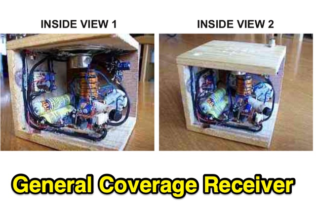 This is a compact three transistor regenerative general coverage receiver with fixed feedback. The sensitivity and selectivity is relative good, especially on the LF and MW bands, as can be expected with this simple design.
 -
 The Aziloop DF-72 antenna system provides 72 K9AY headings and 36 loop axes, allowing for rapid switching in 60 ms. It integrates a switchable 18 dB preamp, a 4-step attenuator (0-18 dB), and four 7-pole preselection filters to optimize receiver performance. The K9AY load is adjustable from 250 Ohm to 950 Ohm in 50 Ohm increments, offering flexibility for various receiving conditions. Control is managed via an intuitive Windows UI, supporting Local, Client, or Server modes, with headless remote operation possible through the built-in Ethernet Server. _Omni-Rig_ support facilitates auto-filter selection, PTT muting, and Rig-Sync functionality, enhancing integration with existing station setups. Designed by _GW4GTE_, the system utilizes a low visual impact, small-footprint antenna with orthogonal loops and an earth connection. It is suitable for general monitoring, co-channel station resolution, basic direction finding, and interference reduction across the VLF to HF spectrum.
 -
 KISS703 is a 703 Hz narrowband digital mode for amateur radio, designed for simple, low-power operation without computers. A 500 Hz pilot tone ensures frequency alignment, replaced by unique tones for 37 symbols (letters, numbers, space). Built from common discrete components, it draws about 40 mA at 12 V, ideal for SOTA/IOTA use. The receiver uses amplification, wave shaping, and a pulse-counting frequency meter for manual decoding via a calibrated meter. Transmitter and receiver calibration involves marking meter positions for each tone, enabling fully self-contained messaging with minimal hardware in portable or fixed operations.
 -
 Demonstrates the construction of an active loop converter specifically designed for the Low Frequency (LF) bands, addressing common localized noise interference in LF reception. The design integrates a sharply tuned circuit and a tuned loop antenna, utilizing the loop as the sole tuned inductive element. By applying positive feedback, the converter significantly increases the loop's effective Q, achieving factors between 1000 and 2000, which sharpens tuning and reduces noise. The circuit employs an _NE602_ mixer stage, feeding its output to an HF receiver, with a crystal-locked local oscillator at 4 MHz. A 20-turn, 0.8-meter square loop antenna with 500 uH inductance is detailed, connected via 2 meters of figure 8 flex cable. The converter offers three selectable frequency bands: 195-490 kHz, 150-220 kHz (including the New Zealand amateur band), and 128-160 kHz (covering the European amateur band). Performance measurements indicate an effective 3dB bandwidth of approximately 100 to 200 hertz at 200 kHz. The article provides insights into component selection, including an _LF353_ op-amp and a trifilar wound transformer on a ferrite core. Sensitivity figures are presented, showing 7.5 uV of converted output per 1 uV/meter signal strength into a 50-ohm load, or 37.5 uV into an _FRG7_ receiver, highlighting its capability to extract weak signals from noise.