Search results
Query: power amplifier 5 watts
Links: 15 | Categories: 0
-
 Constructing a high-power solid-state amplifier for HF operations presents unique challenges, particularly when aiming for significant output like 600 watts. This project details an amplifier design employing **Motorola MRF150** FETs, a common choice for their robust performance in RF power applications. The design emphasizes achieving substantial power output, a critical factor for effective DXing and contesting, where every decibel can make a difference in signal propagation and readability. While specific circuit diagrams or construction details are not directly presented on the current page, the mention of MRF150 FETs points towards a design that would typically involve push-pull configurations, impedance matching networks, and robust power supply considerations to handle the high current demands. Such amplifiers are often built with an eye towards linearity and efficiency across the HF bands. Amateurs pursuing similar high-power solid-state projects often share insights on thermal management, intermodulation distortion, and component sourcing, all vital for a stable and reliable amplifier capable of delivering 600 watts into a proper antenna system.
 -
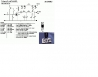 An RF power amplifier, providing 7 Watts output in HF bands, schematic by ON6MU
 -
 VU2RAR basic VHF power amplifier suitable for 144-146 Mhz output power can vary from 3 to 25 Watts.
 -
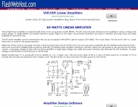 The 60 Watt linear amplifier is simple all solid state circuit using power mosfet IRF840.
 -
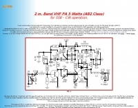 A VHF power amplifier made with two cheap RF transistors, 2N3924 as driver and a BFS22A for final stage, giving an unexpected output power of 7-8 watts maximum
 -
 A lower power desktop linear with integrated 120vac power supply. This, very compact, dual 811 version will deliver about 300 watts output. Covers all bands including WARC bands.
 -
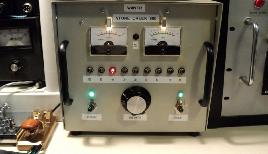
 This article loaded with nice pictures and schematics, describes a 160-10 meter linear amplifier that uses a pair of 3-500Z triode power tubes. It was designed and constructed by William Moneysmith, W4NFR. The amplifier features fast warm up and 1500-Watt RF output with 100-Watts of drive.
 -
 The resource details the construction of a homebrew 50-watt FET amplifier, based on Don W6JL's _QST Homebrew contest_-winning design from 2009. It functions as an afterburner for QRP transceivers, providing a **12dB** power lift. The amplifier utilizes IRFZ24N FETs and covers the 80, 40, 30, and 20-meter bands, with the 20m LPF extending to 17m. Key technical aspects include an FT37-43 transformer for the input network, a relay-switched 3dB pad for lower bands controlled by an _Arduino Nano_, and an RF-actuated T/R switch. The LPF board integrates four relay-switched filters rated for 50 watts, using capacitors with a minimum 250VDC rating. Performance measurements indicate a power gain ranging from **4.4dB** on 20m to 8.1dB on 80m, with a required drive power of approximately 5 watts. The article also discusses thermal management, current limiting considerations, and component sourcing.
 -
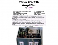 1500 watts of RF output on the 70cm band requires robust amplifier design, a challenge addressed by this project featuring the GS-23b / 4CX1600U Svetlana tube. The resource details the construction of a high-power UHF amplifier, providing insights into component selection and layout necessary for stable operation at these frequencies and power levels.
 -
 Constructing a high-power 70cm solid-state amplifier presents unique challenges, particularly when aiming for 500 watts output using modern LDMOS devices. This resource details the author's experience building a 70cm amplifier based on a _Freescale MRFE6VP5600H_ transistor, initially from an RFHAM kit. It meticulously outlines the necessary modifications to achieve advertised performance, including optimizing input and output matching, correcting bias circuitry, and ensuring proper output balun connections for stability. The author shares specific adjustments, such as trimming the prototyping board for better transistor fit, drilling additional mounting holes for improved heat sinking, and replacing original matching capacitors with a single _20pf MIN02 metal mica_ for superior output. A critical fix involved jumpering gate decoupling pads to balance the push-pull transistor halves, which increased output to 580W and improved IMD. The resource also highlights a crucial correction to the output balun connection, initially reversed in the _Dubus_ article schematic, which resolved intermittent stability issues. Test results are provided, showing input power, output power, and drain current at 50V, demonstrating the amplifier's performance after modifications. This practical account offers valuable insights for hams undertaking similar high-power UHF amplifier projects, especially those working with LDMOS devices and kit-based constructions.
 -
 Demonstrates the construction of a high-power 6-meter (50 MHz) amplifier, specifically designed for demanding modes like EME, TEP, and multiskip Es. It details the use of a _GU-43B_ tetrode in a grounded-cathode configuration, emphasizing the need for stabilized grid voltage and input capacitance compensation. The resource provides a comprehensive schematic, power supply design, and practical considerations for component sourcing, particularly for high-voltage and high-current sections. The builder achieved an output power of **1250 watts** with an anode current of 0.65 amperes and 3200 volts anode voltage. The article also covers the physical construction within a modified P6-31 enclosure, outlining the internal layout for RF and power supply sections, and includes photos of the completed unit. It highlights critical safety precautions for working with high voltages and reactive currents up to **20 Amperes** in the P-network.
 -
 This is a Solid State Amplifier Project. It uses 4 MRF150 MosFet Power Transistors. The Power Supply Voltage is 50 VDC at 21.5 Amp. The max power available is 1,075 Watts. The Efficiency is about 65% +/- and runs Class AB Solid State.
 -
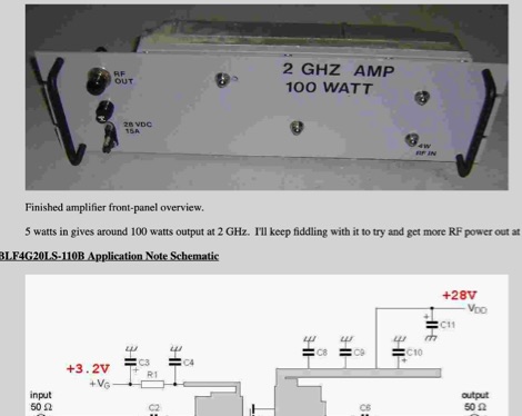 Modification to an old cellular phone base station modules, with a fairly reduced output power (10 watts or so), the stock power amplifier modules will cover the 2.3 GHz and 2.4 GHz amateur radio bands.
 -
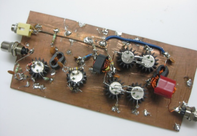 JBOT stands for Just a Bunch of Transistors. It is a simple, stable and easy to build 5 watts linear amplifier build out of a bunch of ordinary low power NPN transistors.
 -
 An Arduino-based interface provides a remote tuner call command for Icom **IC7700** and **IC7800** transceivers, addressing the lack of a built-in function for external tuners such as the MFJ 998RT. This setup initiates a low-power transmit signal, typically 15 watts, allowing the remote autotuner to perform its matching sequence. The article details the required CI-V line communication and modifications to existing Arduino code, specifically referencing contributions from Jean-Jacques ON7EQ for improved Icom interrogation routines. The system involves a sequence of steps: storing the transceiver's current mode and power, disabling the internal autotuner, activating a control relay to interrupt the amplifier line, switching to RTTY mode at low power, and initiating transmit. The transmit duration is manually controlled by the operator, observing the SWR meter until a low SWR is achieved, then a second button press stops the transmission. A built-in 4-second transmit limit provides a safety measure. After tuning, the routine restores the original mode and power settings, re-enables the internal autotuner, and performs a brief 2-second RTTY transmission for internal tuner adjustment. The circuit diagram includes a Panasonic form 2 relay for amp control and emphasizes critical delays in the Arduino code for stable operation at 9600 baud CI-V communication. Compatibility with logging software like DXLab, N1MM, and N3FJP is noted, with specific interrogation time settings required to avoid conflicts.