Search results
Query: receiver circuit
Links: 43 | Categories: 1
-
 Presents a collection of homebrew amateur radio projects and circuit ideas developed by EA5/G3PTO, a licensed operator since 1961. The resource details various transmitters and receivers constructed for frequencies ranging from 1.8 MHz to 10 GHz, emphasizing CW and BPSK31 operation. Specific projects covered include a "Bombproof 7Mhz Receiver" and several keying circuits, providing insights into designs that have proven effective over decades of use. The site also integrates personal photography, showcasing scenes from the West of England and Southeast Spain, reflecting the author's interest in connecting with other amateurs and visualizing their locations. Additionally, it offers a curated list of links to other home construction sites and DX information, serving as a hub for DIY enthusiasts and DXers. The content is distinctively personal, blending technical project documentation with a broader view of the amateur radio lifestyle and community engagement.
 -
 This web page describes a small, single tuned circuit regenerative receiver primarily for daylight reception in the 16, 19, 22 and 25 meter international shortwave broadcast bands.
 -
 The Elecraft K3, a popular HF transceiver, is often benchmarked against new market entrants. This article critically compares the Kenwood TS-590S to the K3, focusing on key technical specifications and operational aspects relevant to serious amateur radio operators. The author proposes three distinct evaluation methods: a circuit diagram comparison, an independent review analysis (referencing Peter Hart, G3SJX, in RadCom), and a real-world "ear test" by experienced contest operators on 40 and 80 meters. The analysis delves into specific receiver components, including the first mixer design, RF and IF amplifier performance, and the presence of an image noise filter. It highlights the K3's switched mixer and the potential for the TS-590S to utilize similar or improved designs, such as a classic filter with enhanced selectivity. The article also scrutinizes the second mixer stage, noting the K3's SA612 chip and its associated IP3 limitations, suggesting Kenwood might achieve benefits with a different mixer architecture. Further points of comparison include DSP capabilities, where the K3's high-performing DSP with KK7P's involvement is noted against the TS-590S's potential reliance on newer IC technology but possibly less refined software. The discussion extends to DDS and PLL implementations for phase noise and spurious emissions, and the utility of a second receiver for DX chasing and contesting, acknowledging its importance for some operators while being less critical for others. The article concludes by emphasizing personal preference in equipment selection.
 -
 PA3FWM's software defined radio (SDR) page documents his extensive hardware and software development efforts between 2004 and 2009. Initial experiments utilized a direct conversion receiver with 90-degree phase difference, feeding a PC soundcard at 48 kHz sample rate, covering 24 kHz of spectrum around a 7080.5 kHz local oscillator. This setup, similar to AC50G's QEX 2002 article, allowed for basic I/Q signal processing to distinguish signals above and below the LO frequency. Limitations included fixed crystal frequencies, 16-bit dynamic range, and narrow bandwidth. Subsequent hardware iterations aimed for enhanced performance, incorporating external 24-bit ADCs with 192 kHz sample rates, connected via 10 Mbit/s Ethernet. A **MC145170-based PLL** and programmable octave divider provided a 58 kHz to 30 MHz tuning range. The **Tayloe mixer** was employed, with differential outputs feeding a PCM1804 ADC. An ATmega32 microcontroller handled serial data conversion to Ethernet frames, though without CRC calculation due to processing constraints. Later designs integrated AD7760 2.5 Msamples/second ADCs and a Xilinx Spartan-3 FPGA, enabling direct reception of 0-1 MHz spectrum and eventually 2.5 MHz bandwidth across the shortwave spectrum. Software was refactored to use an initial 8192 non-windowed FFT for efficient high-bandwidth processing. The project culminated in a two-way QSO on 21 MHz using the developed hardware and software, demonstrating transmit capabilities with a D/A converter. The system exhibited a 2.5 MHz wide spectrum display and a zoomed 19 kHz display, capturing signals like ionospheric chirp sounders and RTTY contest activity. Challenges included noise leakage from digital circuitry and cooling for high-power dissipation components.
 -
 Constructing a functional spectrum analyzer for the 0-100 MHz range presents a significant challenge for radio amateurs, often requiring specialized components and careful calibration. This project details a homebrew spectrum analyzer design utilizing common integrated circuits like the _SA605D_ FM receiver IC and _MAR-6_ MMIC amplifiers, aiming for a cost-effective solution. The design incorporates a low-pass filter, RF amplification, a voltage-controlled oscillator (VCO) for downconversion, and multiple IF stages at 150 MHz and 10.7 MHz, with a resolution bandwidth (RBW) of 15 kHz. Critical components such as the _SBL-1_ mixer and varicap diodes are specified, alongside instructions for winding inductors and tuning filters. The analyzer's performance is discussed in terms of input level limitations, specifically the 1dB-compression point and third-order intercept point, to ensure accurate measurements and prevent component damage. The _SA605D_'s logarithmic Received Signal Strength Indicator (RSSI) output serves as the detector, driving the Y-input of an oscilloscope, while a _TL084_ op-amp generates the sweep signal for the X-input. Potential enhancements include adding a step attenuator, improving front-end filtering, and implementing switchable IF filters for variable RBW, allowing for greater versatility in analyzing RF signals.
 -
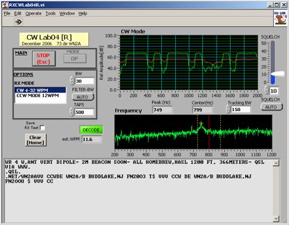 Deciphering weak or noisy **CW** (Continuous Wave) signals often presents a challenge for amateur radio operators, particularly in contest environments or during DXpeditions. CWLab04X addresses this by providing a software solution that leverages **DSP** (Digital Signal Processing) capabilities of a soundcard to decode Morse code. It functions as both a receiver and a sender, supporting traditional CW and a unique "CCW" mode designed to enhance copyability of signals struggling against high noise floors. The program offers two installation methods: a Windows-specific installer for straightforward setup or a zipped package compatible with Windows and Linux systems running Wine. Users must first download and review the accompanying PDF documentation, CWLab04.pdf and CWLab04_Hardware.pdf, which detail the software's operation and the necessary soundcard interface circuit. The hardware PDF outlines a direct connection from the receiver audio output to the soundcard input, with optional conversion of the soundcard output for hard-keying or microphone input. CWLab04X is intended as an operational aid rather than a replacement for skilled human copy, particularly highlighting the effectiveness of its CCW mode in adverse signal conditions. The software was last revised in April 2009, with installation requiring the LV Runtime 602.
 -
 Examines the historical landscape of "boat anchor" amateur radio equipment manufacturers, focusing on the technical innovations and market dynamics that shaped the industry from the pre-WWII era through the transition to SSB. It details the origins and key product lines of prominent U.S. companies like _Collins Radio Company_, _Central Electronics_, and _Barker & Williamson_, highlighting their contributions to receiver and transmitter design. The resource contrasts early AM technology with the advent of SSB, explaining the circuit changes required in receivers and the complete rethinking needed for transmitters. It discusses the impact of military contracts on company survival and the eventual shift towards smaller, self-contained transceivers. Specific examples, such as the _Collins R-390/URR_ receiver and the _Central Electronics 100V/200V_ broadband transmitters, illustrate the engineering prowess and design philosophies of the era, offering insights into their operational characteristics and enduring appeal among collectors.
 -
 Details Guglielmo Marconi's foundational contributions to radio communication, highlighting his 1898 Patent **7777** which introduced tuning circuits for independent simultaneous communications. Chronicles the historic transatlantic reception of the Morse code letter 'S' on December 12, 1901, from Poldhu, Cornwall, to St. John's, Newfoundland, a distance of over _3,500 kilometers_. The exhibit showcases early Marconi 10-inch spark transmitters, identical to those used on the _Titanic_, alongside Canadian Marconi crystal detector models. It also features high-end commercial receivers like the IP501, weighing **87 pounds** and originally priced at $595.00, demonstrating the robust construction and technological advancements of the era.
 -
 The Collins TRC-75 autotune linear amplifier, owned by JF2SVU, is presented with a focus on its internal modifications. This QRO amplifier utilizes three 4CX250 tubes in parallel for its final stage, delivering 1 KW output power. Notably, the amplifier achieves full power with only 100 mW of RF input, a characteristic often associated with Collins designs. The original 400 Hz power supply has been converted for easier shack integration, and the entire RF and power supply sections have been rehoused into a compact, clean enclosure. The control unit, positioned above the amplifier, features three meters for individual vacuum tube IP monitoring and a multi-meter on the right. A dedicated 7 MHz receiver, recently completed, is also part of this integrated system. The autotune functionality means the main amplifier unit only requires connections for power, control, and coaxial cables, simplifying its operation. Key components like the 4CX250 tubes and NF capacitors are visible, along with the gearing mechanism for the final tank circuit. A timer and relay system manages high-voltage delay and cooling fan off-delay, although the cooling fan's airflow is noted as somewhat insufficient. A central volume control, which experienced a contact issue, is also highlighted.
 -
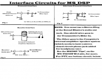 Minimal interface circuits for receiver and transmitter audio, also for PSK31
 -
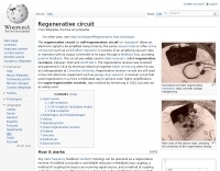 Wikipedia page about regenerative circuits in designing receivers.
 -
 For amateur radio operators engaged in **radio direction finding** (RDF) and **transmitter hunting** (T-hunting) activities, this resource provides a catalog of printed circuit boards (PCBs) for constructing various DF and foxhunt-related projects. The offerings include PCBs for 80-meter fox transmitters and receivers, UHF fox transmitters with audio recording capabilities, and several designs for general-purpose radio direction finders. Specific projects like the "Simple 80M ATX-80 Transmitter" and the "N0GSG DSP Radio Direction Finder" are listed, along with attenuator boxes and specialized components for Doppler DF systems. The catalog details PCBs for projects published in prominent amateur radio magazines such as *73's*, *CQ*, *QST*, and *PE*, indicating their origin and design pedigree. For instance, the "Montreal Fox Controller" is sourced from the *Homing-In* column by Joe Moell, K0OV. The resource also lists components for advanced Doppler DF systems, including main boards, LED display boards, and antenna switch boards, with options for programmed PIC microcontrollers. Pricing for each PCB is provided, allowing hams to acquire the necessary components for their DIY RDF endeavors.
 -
 Operating on the 2200m band (135.7-137.8 kHz) often presents challenges for amateur radio transceivers, which typically exhibit poor receiver performance at these very low frequencies. This project addresses the issue by providing a design for a dedicated 137 kHz antenna preamplifier, specifically tailored to improve signal reception for radios such as the _Yaesu FT-817_. The preamplifier circuit utilizes a low-noise FET input stage, crucial for minimizing self-generated noise and maximizing the signal-to-noise ratio from weak LF signals. The design includes a detailed schematic, component values, and construction notes, enabling homebrewers to build a functional unit. The goal is to achieve significant gain, making the faint signals on 2200m more discernible and improving overall band usability. Key design considerations include impedance matching to typical antenna systems and ensuring stable operation across the narrow LF segment. The circuit aims for a **low noise figure** and sufficient amplification to overcome the inherent limitations of general-purpose HF transceivers when operating below **200 kHz**.
 -
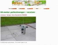 80-meter peilontvanger / receiver includes printed circuit sample and list of components
 -
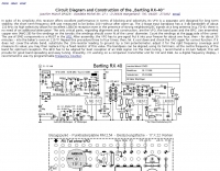 Circuit Diagram and Construction of the Bartling RX-40 Joachim Munch DF4ZS
 -
 Schematic of a homebrew receiver and keying
 -
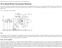 The direct conversion receiver described consists of only a bandpass filter, mixer IC, VFO and audio filter. With only 22 parts, this simple circuit should take a few hours at the weekend to construct.
 -
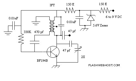 A simple free running oscillator oscillating at the receiver\'s IF (intermediate frequency) beats with the incoming signals in either CW or SSB and the resultant audio frequency goes to the AF amplifier.
 -
 Collection of several Crystal Radio receiver circuits with schematics diagrams and pictures
 -
 The _Sci.Electronics FAQ: Repair: RFI/EMI Info_ document, authored by Daniel 9V1ZV, provides a detailed analysis of computer-generated RFI/EMI, focusing on its impact on radio reception. It identifies common RFI sources such as CPU clock rates (e.g., 4.77 MHz to 80 MHz), video card oscillators (e.g., 14.316 MHz), and even keyboard microprocessors, all of which generate square-wave harmonics across HF and L-VHF regions. The resource outlines a systematic procedure for pinpointing RFI origins, including disconnecting peripherals and using a portable AM/SW receiver with a ferrite rod antenna to localize strong interference sources. The document categorizes RFI mitigation into shielding, filtering, and design problems, offering practical solutions for each. It recommends applying conductive sprays like _EMI-LAC_ or _EMV-LACK_ to plastic casings of radios, monitors, and CPUs to create effective Faraday cages, emphasizing proper grounding and avoiding short circuits. For filtering, the guide suggests using line filters, ferrite beads, and toroids on power and data lines, and small value capacitors (e.g., 0.01 uF for serial/parallel, 100 pF for video) to shunt RFI to ground. It also discusses the use of bandpass, high-pass, low-pass, and notch filters on the receiver front-end or antenna feed to combat specific in-band noise.
 -
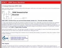 Christoph Petermann DF9CY DRM demonstration receiver project including Circuit Diagram and component list
 -
 A cavity filter, often a critical component in _duplexer_ designs, functions as a sharply tuned resonant circuit, allowing only specific frequencies to pass while attenuating others. These filters are essential for maintaining signal integrity in environments where multiple transmitters and receivers operate simultaneously on closely spaced frequencies, such as in repeater stations. The article details how these filters, sometimes referred to as _notch filters_, achieve high Q factors, which are crucial for their performance. Understanding the principles of cavity filters is fundamental for any amateur radio operator involved in repeater operation or designing custom RF front-ends. The discussion covers the basic circuitry and operational characteristics that enable these devices to provide significant isolation, often achieving **-80 dB** or more between transmit and receive paths. This level of isolation is vital for preventing receiver desensitization and intermodulation distortion. Properly tuned cavity filters ensure that a repeater can transmit and receive simultaneously on different frequencies without self-interference, a common challenge in VHF/UHF operations.
 -
 Maintaining vintage Eddystone receivers often presents unique challenges, as detailed by Victor Jenkins in his refurbishment of an EA12, where his deep understanding of RF circuits ensures optimal performance for daily shortwave listening. Similarly, Gerry O’Hara VE7GUH, a prolific contributor to the EUG website and a trustee, meticulously documented his restoration of an Eddystone S830/2, even addressing an unusual instability issue with a follow-up postscript article and YouTube videos demonstrating the fix. His work, along with numerous other articles on the "Restorations" page, showcases a master's approach to bringing vintage sets back to factory specifications or better. Beyond technical restorations, the EUG also shares compelling historical narratives. One such story recounts the discovery of a long-lost 78rpm recording featuring Eddystone Radio Ltd.'s founder, George Stratton Laughton, and other key figures discussing the company's wartime and post-war contributions to shortwave communications. This six-minute BBC production, transcribed into an MP3 file by Peter Carney, offers a rare auditory glimpse into the company's legacy, highlighting its role in supplying equipment to police, ministries, and expatriate British workers. The community aspect thrives through shared experiences, like Roger Trickett's anecdote about his Eddystone EC10, which has been continuously powered for 50 of its 54 years, traveling across continents and enduring various modifications. Another intriguing account from Roy GM4VKI details the "S640 Identity Crisis," where a seemingly standard S640 receiver turned out to be a masterfully engineered 80/20-meter SSB transceiver built into the original chassis by GI3ZX, showcasing incredible ingenuity from a bygone era of amateur radio.
 -
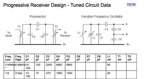 Tuned circuits for Progressive Receivers
 -
 Presents the full owner's manual for the _Drake R-4C_ communications receiver, specifically a late version edition. This resource outlines the comprehensive operational instructions, covering everything from initial setup and tuning to advanced features and controls. Hams can reference detailed diagrams and explanations for proper signal reception across various amateur bands. The manual includes critical information for alignment procedures, ensuring the receiver performs to its optimal specifications. It details the steps required for calibrating the internal circuitry, which is essential for maintaining sensitivity and selectivity over time. My experience with vintage Drake gear confirms the value of these original documents for accurate adjustments. Furthermore, the document provides insights into troubleshooting common issues and performing routine maintenance. It serves as an authoritative guide for anyone operating or servicing this classic piece of amateur radio equipment, helping to preserve its functionality for years of DXing and ragchewing.
 -
 A 0-30 MHz step attenuator, constructed from switchable Pi attenuation pads, provides a practical tool for evaluating receiver sensitivity and calibrating S-meters. The design utilizes readily available 5% tolerance resistors, with values derived from paralleled components to achieve specific attenuation steps. A schematic (Fig 1) illustrates the circuit, including PCB pad shielding, while a table details required and actual resistor values, along with percentage differences. Measurements of voltage input versus output at various frequencies are used to calculate dB attenuation, presented in a graph (Fig 4). The resource includes formulas for determining output voltage from a known input and a comprehensive 0-40 dB voltage multiplier table, which is crucial for precise signal level management. The project also references external attenuator calculators and equations for further study. Photos (1-3) provide visual guidance for the assembled unit, showing bottom, top, and front views. The project emphasizes the use of **Pi attenuation pads** and **receiver sensitivity** evaluation, offering a hands-on approach to RF signal management.
 -
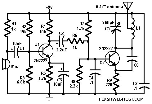 This FM wireless mike can transmit voice signals to any FM Radio receiver 100 meters away.
 -
 Amateur Packet Reporting System (APRS) operations often require compact, reliable solutions for transmitting position data, particularly for mobile or portable stations. This resource details the construction of the _Tiny Track-I_, a transmit-only APRS tracker designed for straightforward integration with a VHF radio and a Global Positioning System (GPS) receiver. It enables hams to broadcast their location without the complexity of a full-duplex TNC. The project outlines the printed circuit board (PCB) layout and schematic, based on an original design by N6BG, with a personal PCB drawing by SV1BSX. It includes specific component placement and notes an additional 10uF/10V capacitor (C5) for improved IC voltage decoupling, a modification not present in the original N6BG diagram. The unit connects to a computer or GPS via a DB9 female connector. This tracker is ideal for basic position reporting, offering a simple and effective way to participate in APRS networks. Its small footprint makes it suitable for vehicle installations or field deployments where space is limited, providing a **reliable 9600 baud** data stream for location updates.
 -
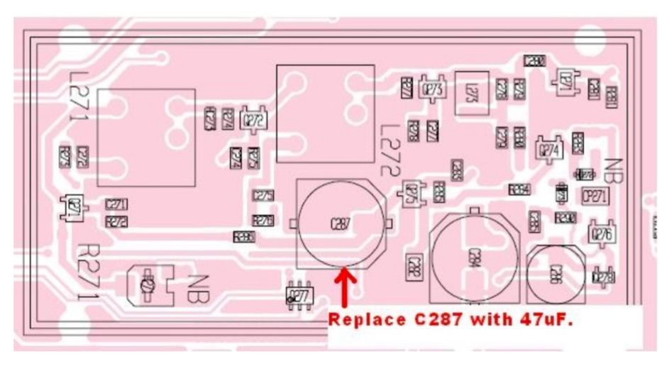 If your 756 has lots of noise with crackles and sweeping heterodynes, especially noticeable on AM, it may be due to a faulty electrolytic capacitor in the noise-blanker circuit
 -
 Operating in a Single Operator Two Radios (SO2R) setup, especially with beverage antennas, often exposes the receiving radio's front-end to significant RF energy from the transmitting radio. This resource details a practical, homebrew receiver protection circuit designed to mitigate this risk. The core of the design involves a non-inductive 2W 22 Ohm carbon composition resistor in series with the RX antenna line, followed by two stacks of four fast-switching diodes (e.g., _1N914_) configured in opposite polarizations. This arrangement effectively clamps the incoming voltage to approximately 2.8 V peak-to-peak, safeguarding sensitive receiver input components. The series resistor plays a crucial role by absorbing excess power, preventing the diodes from exceeding their current ratings and potentially failing open, which would leave the receiver unprotected. The author, _N4KG_, measured up to 50 watts of coupled power between 80M slopers on the same tower, highlighting the necessity of such protection. The design is presented as a cost-effective solution to prevent damage to receiver input transformers, with the author noting successful protection of a receiver even after a resistor showed signs of overheating. This simple circuit can be integrated via a transverter plug, offering a robust defense against high RF input.
 -
 If You are using a separate receive antennas then you need a good protection circuit to eliminate the possibility of blowing out the receiver front-end while using these auxiliary receive antennas specially on low bands.
 -
 Home made 40 meter transceiver project. The receiver is a Progressive Receiver with a few modifications. The Transmitter is a modified MFJ Cub circuit. Includes schematic and circuit diagrams for Receive Input Filter, 3-Pole 500 Hz Cohn Filter and 7 MHz Double Tuned Bandpass Filter
 -
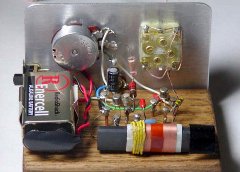
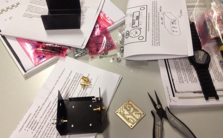
 A simple superheterodyne receiver (3.5–30 MHz) for amateur radio achieves stable SSB-CW reception using modern BJTs, an AD831 mixer, a 6-pole quartz filter, and Seiler oscillators. Designed with high IF (4.5 MHz), compact AM-FM variable capacitors, and modular resonant circuits, it ensures selectivity, image rejection, and stable tuning. Built in a copper-lined wooden case, it features practical assembly techniques but lacks advanced features like AGC or S-meter. Effective on basic antennas, it achieves global reception.
 -
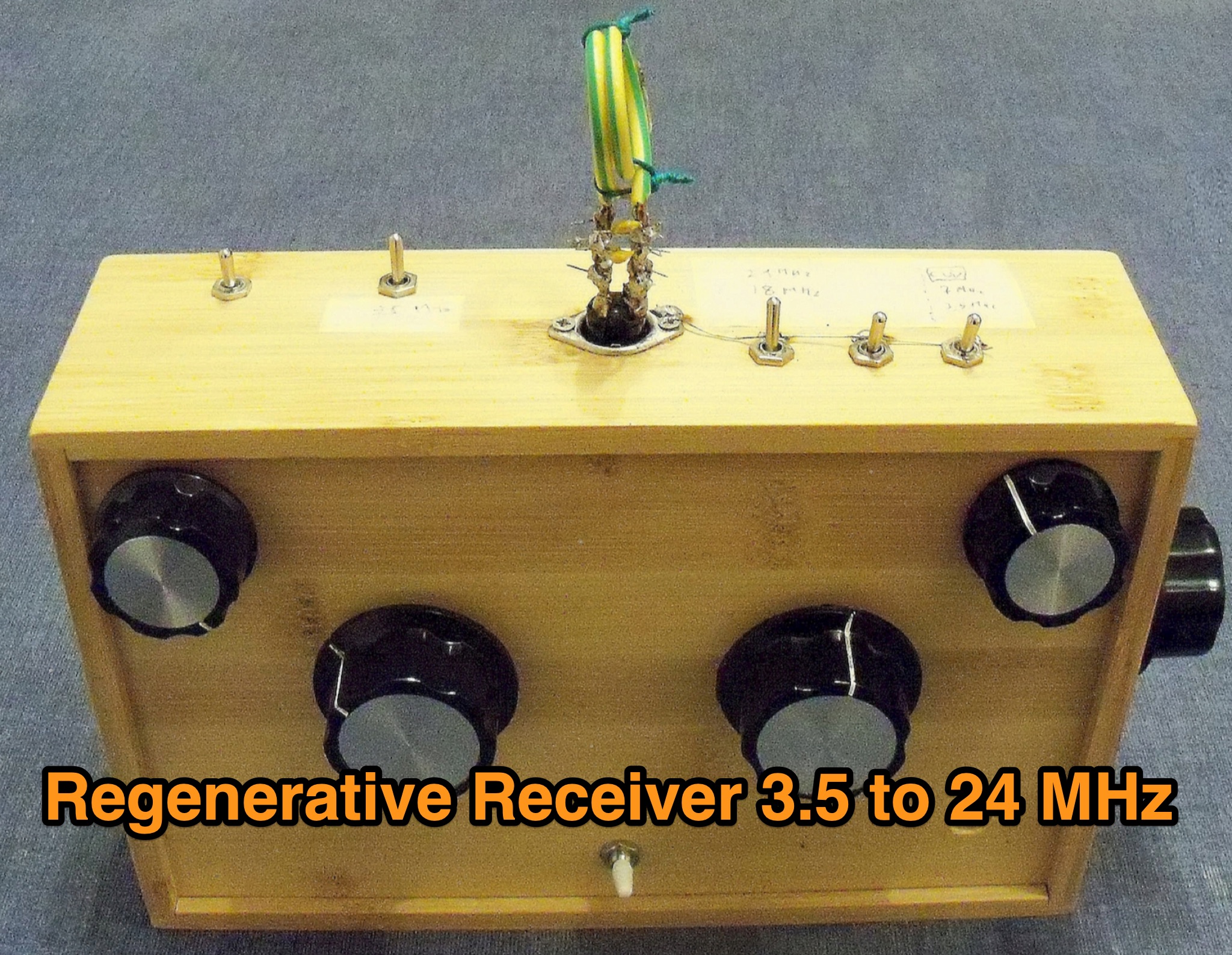 A 3.5–24 MHz regenerative receiver for amateur bands was recently constructed, inspired by a 1934 design. The project was both challenging and rewarding, requiring precise tuning and high-quality components. The receiver successfully captured QSOs from across the globe, such as New Zealand communicating with Panama. The simplicity of the design and the satisfaction of building a functional, compact wooden box with handmade resonant circuits were highlights. This project demonstrates a meaningful way to reconnect with the roots of amateur radio.
 -
 This PDF article introduces a series of dual-tuned bandpass filters designed for input tuning in amateur band receivers. Developed by Stefen Niewiadomski, these filters feature 50-ohm input/output impedance and can be cascaded for improved roll-off outside the passband. The designs use readily available TOKO coils, with taps on the tuned winding for matching input circuits with impedances around 1k ohm. The inductors are core-tuned, with average inductance values provided for easier matching to other inductors.
 -
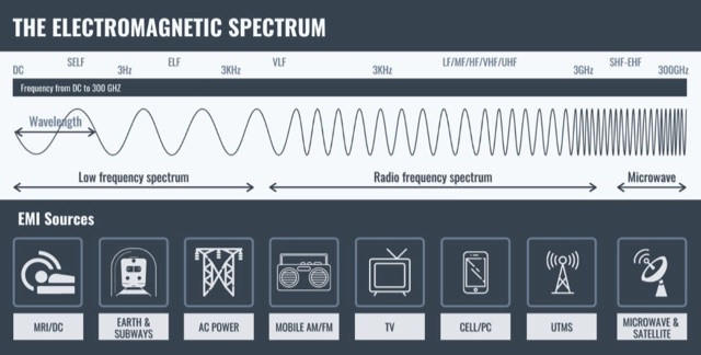 Radio Frequency Interference (RFI) has always been a source of concern for the Radio Amateur. Until the recent introduction of complex circuitry in the home, our communications gear has been the main source of potential RFI. In this computerized age of ours, increasingly complex and sensitive receivers are being barraged by these and other sources of RFI.
 -
 This article details the design and construction of a compact 20-meter QRP SSB transceiver by Pete Juliano, N6QW, measuring just 2 x 4 x 2 inches—small enough for a shirt pocket. Inspired by a 1963 QST design and refined from a prior version, it employs bilateral circuits, a 4.9152 MHz homebrew crystal filter, switched-crystal VXO for 60 kHz coverage (14.160-14.220 MHz), and standard components like ADE-1L mixers and IRF510 PA for 1W output. Key innovations include a double-sided PCB skeletal frame for shielding and isolation, Vectorboard sub-assemblies, and ultra-miniature relays. The bilateral receiver/transmitter shares stages, omitting AGC for simplicity, while a W3NQN LPF and optional 10W external amp enable DX contacts. Tune-up focuses on crystal matching and bias for linearity. Videos on YouTube demonstrate performance, confirming excellent stability and audio. Total cost nears $100, prioritizing portability over features like CW.
 -
 Chavdar Levkov, LZ1AQ, presents an experimental comparison of small wideband magnetic loops, building on his previous work on wideband active small magnetic loop antennas. His research focuses on increasing loop sensitivity by maximizing the short-circuit current, which is directly tied to the "loop factor" M = A/L, where A is the equivalent loop area and L is its inductance. Levkov's methodology involves reducing inductance and increasing area through parallel or coplanar crossed (CC) configurations, comparing these designs against a reference single quad loop of 1 m2 area. Experimental verification included testing three distinct loop types: a simple quad loop, two coplanar crossed (CC) loops, and eight parallel loops, all designed to have a total geometric area of 1 m2. Measurements were conducted at 1.8, 3.5, 7, and 10 MHz using a small transmitter 270 meters away, with a Perseus direct sampling receiver for precise signal level assessment. The results consistently showed that CC loops, particularly Loop 5 (two CC circular loops with 1.44 m2 total area), yielded significantly higher currents, up to 9.1 dB over the reference loop at 3.5 MHz, validating M as a reliable predictor of loop sensitivity. Numerical simulations using MMANA further corroborated the experimental findings, demonstrating an almost perfect correlation between the calculated M factor and the induced loop current for 15 different loop models. Levkov concludes that CC loops offer superior sensitivity for a given loop area, while parallel loops are advantageous for minimizing physical volume. Practical recommendations suggest using loops with an M factor greater than 0.5 uA/pT for quiet rural environments, and he provides a spreadsheet tool, WLoop_calc.xls, to aid in optimizing loop configurations for specific operational needs.
 -
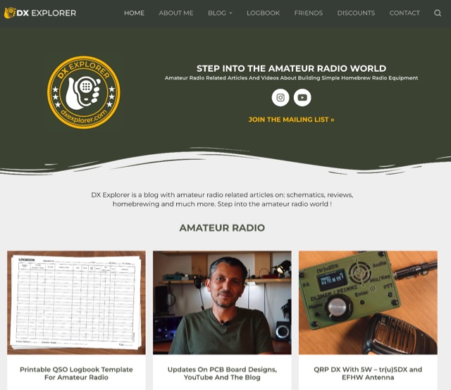 The _DX EXPLORER_ blog serves as a personal chronicle of amateur radio experiences, particularly emphasizing homebrew projects and DIY radio equipment. It provides insights into constructing various transceivers and receivers, such as the Minimalist CW Transmitter and the Sputnik Regenerative Receiver, offering practical guidance for those new to the hobby. The content often details the assembly and operation of low-cost kits like the $3 Pixie Transceiver, demonstrating accessible entry points into radio construction. Beyond building, the site also features reviews of commercial gear, including the Tidradio TD-H8 Radio, providing an operator's perspective on performance and utility. The author, YO6DXE, shares a learning journey, aiming to inspire fellow enthusiasts to engage with the technical aspects of amateur radio. This resource covers a range of topics from basic circuit explanations to practical operating tips, fostering a deeper understanding of radio principles. The blog's focus on personal experimentation and project documentation makes it a relevant resource for hams interested in hands-on learning.
 -
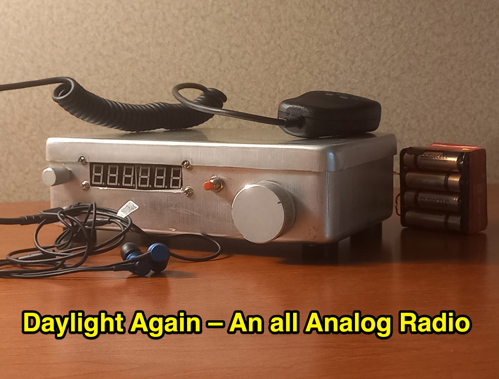 This article discusses a high performance, 7MHz, 5 watt SSB rig, the Daylight Radio, an all-analog radio design from the 1980s that includes a full circuit diagram, IMD NR60 calculations, QER crystal filter, bandpass filter, receiver portion, and more. The author explores the design, components, and functionality of this analog radio for hams interested in vintage or homebrew radio projects.
 -
 The project details the construction of a GM3OXX OXO transmitter, designed to accommodate **FT-243 crystals** using 3D-printed FX-243 holders from John KC9ON. It presents specific frequency adjustments, noting a 7030 KHz HC-49/s crystal could be tuned from 7029.8 KHz to 7031.7 KHz with an internal 45pF trimmer capacitor. The build incorporates a modified keying circuit to prevent oscillator run-on key-up and includes a TX/RX switch for sidetone via a connected receiver, with the transmitter output routed to a dummy load on receive. Practical construction aspects are thoroughly covered, including the process of cutting a rectangular opening in a diecast enclosure for the FT-243 socket and the selection of a **low-pass filter** (LPF) based on the QRP Labs kit, derived from the W3NQN design. The author achieved approximately 800mW output power from a 14.75V supply, measured with an NM0S QRPoMeter, using a 16.5-ohm emitter resistor in the 2N3866 final stage. The article also touches upon the potential for frequency agility across the 40M band using multiple FX-243 units with various crystals. The narrative includes a brief diversion into Bob W3BBO's recent homebrew projects, such as his Ugly Weekender MK II transceiver, highlighting the enduring appeal of classic QRP designs. The author reflects on the personal satisfaction derived from building RF-generating equipment, irrespective of DX achievements, and shares experiences of making local contacts with the 800mW OXO transmitter on 40 meters.
 -
 Demonstrates the construction of an active loop converter specifically designed for the Low Frequency (LF) bands, addressing common localized noise interference in LF reception. The design integrates a sharply tuned circuit and a tuned loop antenna, utilizing the loop as the sole tuned inductive element. By applying positive feedback, the converter significantly increases the loop's effective Q, achieving factors between 1000 and 2000, which sharpens tuning and reduces noise. The circuit employs an _NE602_ mixer stage, feeding its output to an HF receiver, with a crystal-locked local oscillator at 4 MHz. A 20-turn, 0.8-meter square loop antenna with 500 uH inductance is detailed, connected via 2 meters of figure 8 flex cable. The converter offers three selectable frequency bands: 195-490 kHz, 150-220 kHz (including the New Zealand amateur band), and 128-160 kHz (covering the European amateur band). Performance measurements indicate an effective 3dB bandwidth of approximately 100 to 200 hertz at 200 kHz. The article provides insights into component selection, including an _LF353_ op-amp and a trifilar wound transformer on a ferrite core. Sensitivity figures are presented, showing 7.5 uV of converted output per 1 uV/meter signal strength into a 50-ohm load, or 37.5 uV into an _FRG7_ receiver, highlighting its capability to extract weak signals from noise.
 -
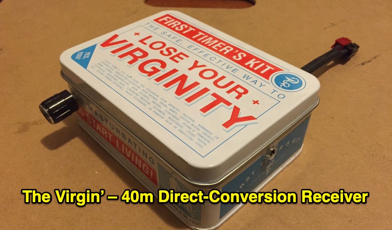 Demonstrates the construction of 'The Virgin', a **direct-conversion receiver** specifically designed for the 40m amateur radio band. This project, completed in February 2016, features a fixed operating frequency determined by a crystal oscillator, requiring a physical crystal change to alter the reception frequency. The design incorporates two integrated circuits and a power regulator, emphasizing simplicity with a single control knob. The author details the initial design, subsequent modifications to the front end, and troubleshooting steps addressing common issues like audio motorboating and power supply instability. The resource presents the final design of the receiver, reflecting the author's first experience building such a unit between December 2015 and February 2016. It offers practical insights into basic circuit construction and the iterative process of refining a homebrew radio project. The content is particularly relevant for those interested in fundamental receiver principles and hands-on **QRP** transceiver building.