Search results
Query: schema receiver
Links: 21 | Categories: 9
Categories
- Technical Reference > Receivers > Progressive Receiver
- Technical Reference > Receiver Front-End Protector
- Technical Reference > Receivers
- Technical Reference > Receivers > Regenerative Receiver
- Technical Reference > Receivers > Crystal radio
- Radio Equipment > Receivers > Drake R-4B
- Technical Reference > Headsets and Speakers
- Technical Reference > HF Radios
- Technical Reference > Radio Mods
-
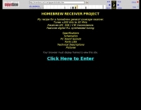 Detailed plans of my homebrew receiver. Frequency coverage is from below 300kHz to 30MHz. Pictures, schematics, board layouts, parts lists and more can be found here.
 -
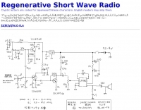 Regenerative short wave radio schematic
 -
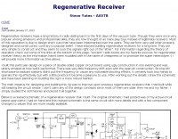 Project and schematic of a regenrative receiver by AA5TB
 -
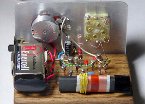
 This is a compact three transistor regenerative general coverage receiver with fixed feedback
 -
 Schematic anc PCB for a fox hunting receiver for 80 meters band
 -
 Hammarlund HQ-129X Receiver, Heathkit C-3 Condenser Checker, Heathkit QF-1 Q-multiplier and more
 -
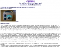
 Operating on the 2200m band (135.7-137.8 kHz) often presents challenges for amateur radio transceivers, which typically exhibit poor receiver performance at these very low frequencies. This project addresses the issue by providing a design for a dedicated 137 kHz antenna preamplifier, specifically tailored to improve signal reception for radios such as the _Yaesu FT-817_. The preamplifier circuit utilizes a low-noise FET input stage, crucial for minimizing self-generated noise and maximizing the signal-to-noise ratio from weak LF signals. The design includes a detailed schematic, component values, and construction notes, enabling homebrewers to build a functional unit. The goal is to achieve significant gain, making the faint signals on 2200m more discernible and improving overall band usability. Key design considerations include impedance matching to typical antenna systems and ensuring stable operation across the narrow LF segment. The circuit aims for a **low noise figure** and sufficient amplification to overcome the inherent limitations of general-purpose HF transceivers when operating below **200 kHz**.
 -
 Digital Amateur Television web sited include a D-ATV transmitter, D-ATV receiver, D-ATV modulator D-ATV schematics by RA3TTS
 -
 Schematic of a homebrew receiver and keying
 -
 A project with schematic to build a receiver for 80 meters band by VK1PK
 -
 Collection of several Crystal Radio receiver circuits with schematics diagrams and pictures
 -
 80 metre ceramix VXO with schematic and assembly instructions
 -
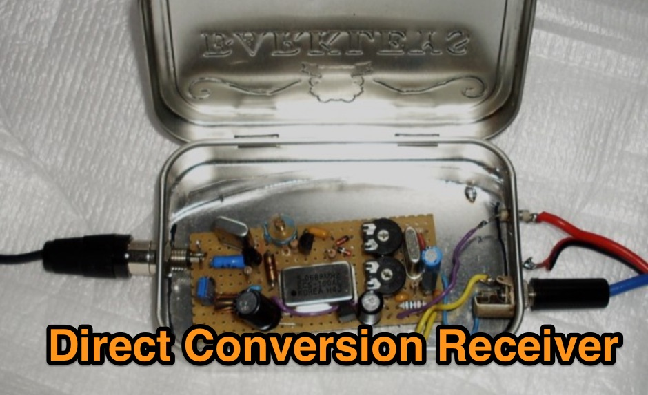 A schematic diagram of a homemade direct conversion receiver for 30 meters band
 -
 A 0-30 MHz step attenuator, constructed from switchable Pi attenuation pads, provides a practical tool for evaluating receiver sensitivity and calibrating S-meters. The design utilizes readily available 5% tolerance resistors, with values derived from paralleled components to achieve specific attenuation steps. A schematic (Fig 1) illustrates the circuit, including PCB pad shielding, while a table details required and actual resistor values, along with percentage differences. Measurements of voltage input versus output at various frequencies are used to calculate dB attenuation, presented in a graph (Fig 4). The resource includes formulas for determining output voltage from a known input and a comprehensive 0-40 dB voltage multiplier table, which is crucial for precise signal level management. The project also references external attenuator calculators and equations for further study. Photos (1-3) provide visual guidance for the assembled unit, showing bottom, top, and front views. The project emphasizes the use of **Pi attenuation pads** and **receiver sensitivity** evaluation, offering a hands-on approach to RF signal management.
 -
 Amateur Packet Reporting System (APRS) operations often require compact, reliable solutions for transmitting position data, particularly for mobile or portable stations. This resource details the construction of the _Tiny Track-I_, a transmit-only APRS tracker designed for straightforward integration with a VHF radio and a Global Positioning System (GPS) receiver. It enables hams to broadcast their location without the complexity of a full-duplex TNC. The project outlines the printed circuit board (PCB) layout and schematic, based on an original design by N6BG, with a personal PCB drawing by SV1BSX. It includes specific component placement and notes an additional 10uF/10V capacitor (C5) for improved IC voltage decoupling, a modification not present in the original N6BG diagram. The unit connects to a computer or GPS via a DB9 female connector. This tracker is ideal for basic position reporting, offering a simple and effective way to participate in APRS networks. Its small footprint makes it suitable for vehicle installations or field deployments where space is limited, providing a **reliable 9600 baud** data stream for location updates.
 -
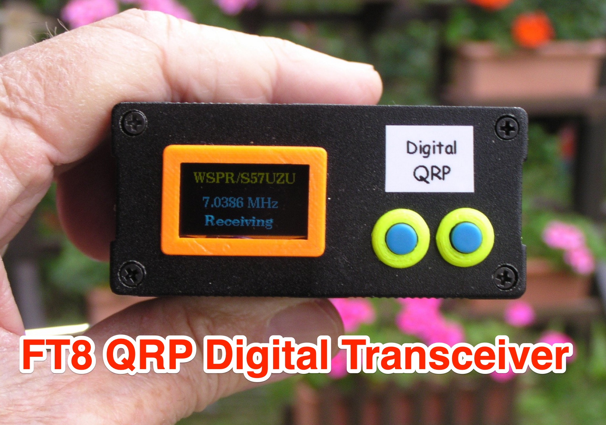 Learn how to build a QRP digital transceiver with Arduino, based on a project by Burkhard Kainka. This article covers the development process, including the source code, modifications made, and the addition of an OLED display for a more professional look. Discover the inner workings of the transceiver, from the receiver to the oscillator, and how components like the CD2003 are utilized. Explore the schematic design, the use of a PLL module Si5351A controlled by Arduino nano, and more. Ideal for hams looking to create their own digital transceiver for amateur radio operations.
 -
 This project revisits a minimalist software-defined radio (SDR) receiver built using a Raspberry Pi Pico, now optimized for simplicity and affordability. Designed for breadboard assembly with through-hole components, the receiver covers 0–30MHz, supporting CW, SSB, AM, and FM modes with an OLED display and spectrum scope. Key improvements include enhanced frequency accuracy, reduced op-amp saturation, and lower-cost components. Powered by three AAA batteries, it delivers standalone operation for global signal reception. Ideal for hobbyists, the design fosters experimentation and is documented with firmware and schematics available online.
 -
 Home made 40 meter transceiver project. The receiver is a Progressive Receiver with a few modifications. The Transmitter is a modified MFJ Cub circuit. Includes schematic and circuit diagrams for Receive Input Filter, 3-Pole 500 Hz Cohn Filter and 7 MHz Double Tuned Bandpass Filter
 -
 The 222 MHz Transverter project, based on Zack Lau's (W1VT) original July 1993 QEX magazine design, provides an IF of 28 MHz for both transmit and receive paths. Rick Bandla (VE3CVG) contributed supplemental notes and construction details, including modifications to achieve 10 mW output power from an initial 4 mW PEP. The design incorporates three distinct boards: a Local Oscillator (LO), a Transmitter (Tx), and a Receiver (Rx), with an estimated parts cost of just over $150 CDN, significantly less than commercial kits. Construction involves both through-hole and surface-mount components, with specific guidance on mounting MAV and MAR devices, grounding techniques, and component selection. The project details include parts lists, schematics for the LO, Tx, and Rx, and board layouts. Troubleshooting advice emphasizes sequential testing, starting with the LO, then Tx, and finally Rx, using a 194 MHz and 222.100 MHz capable FM handheld for signal tracing. Further enhancements are discussed, such as an optional Tx driver stage to boost output to 100 mW and the potential modification of a Motorola Maxor 80 PA for 222 MHz SSB/CW operation. The resource also covers practical aspects like power attenuation pads for IF radios (e.g., FT817) and considerations for enclosure design, including repurposing a Maxor 80 case. Performance reports indicate successful 70 km contacts with only 4 mW output.
 -
 Effective suppression of harmonics and parasitic radiation from HF transmitters is crucial, especially with the increasing sensitivity of VHF/UHF radio channels to interference. This project details a hybrid low-pass filter (LPF) designed to operate across the HF bands up to 51 MHz, making it suitable for 6-meter band operations while providing deep VHF/UHF suppression. The design addresses the challenge of modern interference landscapes, where even microvolt-level signals can disrupt wireless sensors and other simple VHF/UHF receivers. The filter utilizes a single elliptic link, combining high cutoff steepness with robust suppression in the hundreds of megahertz range. A key feature is the use of only two standard capacitor values, simplifying construction and component sourcing. The article provides a detailed schematic, performance characteristics, and _RFSim99_ model file, demonstrating a reflection coefficient S11 below 0.017 (VSWR < 1.03) across 1-51 MHz, ensuring minimal degradation to the antenna system. Construction notes include coil winding specifications and capacitor selection guidance, with recommendations for _FR-4_ assembly. Two capacitor sets are presented, with the first variant recommended for its lower RF current demands, keeping currents below 3 A at 1 kW passing power at 51 MHz. Fine-tuning involves adjusting frameless coils, with considerations for capacitor tolerance and high-frequency capacitance measurement accuracy.
 -
 The RXC70/10 is a sensitive 70 MHz to 10-meterband converter using the Philips SA602 mixer IC. It operates with high stability and low noise, converting 70–72 MHz signals to 28–30 MHz for general coverage receivers. The compact, low-power design (15mA) supports various modulations and uses. Its versatility makes it suitable for amateur radio applications with proper tuning and antenna setup.