Search results
Query: tak antenna
Links: 54 | Categories: 0
-
 Home made vertical antenna for 80 40 15 10 meters ARRL PDF file taken from QST June 1978
 -
 This guide provides step-by-step instructions for constructing a tin can waveguide antenna, commonly known as a cantenna, for enhancing WiFi signal range. The project is budget-friendly, costing under $5, and utilizes easily accessible materials like a food can and basic electronic components. The design is suitable for 802.11b and 802.11g wireless networks, operating within the 2.4 GHz frequency range. To start, gather the necessary parts including an N-Female chassis mount connector, nuts, bolts, and a suitable can. The assembly process involves drilling holes in the can for the connector and mounting the probe. The guide emphasizes the importance of can dimensions and placement for optimal performance, encouraging experimentation for best results. This project is ideal for amateur radio operators and DIY enthusiasts looking to improve their wireless connectivity without significant investment. Safety precautions are advised, as the author does not hold electrical engineering credentials. Users are encouraged to take responsibility for their equipment and ensure proper assembly. With this simple yet effective antenna, users can extend their WiFi coverage and enjoy enhanced connectivity.
 -
 Details the construction of a **multiband vertical** antenna, specifically designed for stealth operation in a rented property, covering 80m, 60m, 40m, and 30m. The author, N3OX, leverages a 12m Spiderbeam telescoping fiberglass pole as the primary support, noting its sturdiness compared to typical fishing rods while remaining light enough for quick deployment and takedown. The radiating element is a 14 gauge Flex-Weave wire, attached to the pole's top with a rubber grommet, and fed by 27 bare 18 gauge radials spread across a 40-foot square backyard. N3OX describes the impedance matching solution, opting for custom-built L-networks over a remote tuner to enable fast bandswitching. Using an MFJ-259B and EZNEC modeling, base impedances were measured and component values calculated with G4FGQ's L_TUNER and SOLNOID_3 programs. The 80m coil is wound on a 3.5-inch PVC form, while the 30m, 40m, and 60m coils are air-wound, self-supporting #10 wire. Variable capacitors are incorporated for 40m and 30m shunt elements, with the 60m impedance matched by a series inductor. The project includes a **servo-controlled** homebrew band switch, utilizing a two-pole 12-position ceramic wafer switch for remote operation, addressing the limited 80m bandwidth. The entire matching network is housed in a weather-resistant shelter constructed from lumber and aluminum flashing. N3OX reports good DX results at 100W, estimating the total cost between $150 and $250, depending on existing parts.
 -
 The **Extended Double Zepp** (EDZ) antenna, a simple wire design, is presented as a means to achieve 3-4 dB of gain on 10 meters, with an overall length of just 43 feet. This resource, authored by WB3HUZ, details several gain antennas suitable for the 29 MHz AM segment, all modeled using EZNEC software at 30 feet above ground. Other designs include a compact rectangular loop, offering more gain than the EDZ and a lower take-off angle, and the **Lazy H**, a bidirectional antenna providing 6 dB gain, which is also workable on 20, 17, 15, and 12 meters. The Bisquare, a diamond-shaped open-top loop, is also featured, providing approximately 4 dB gain and requiring only a single support. These designs are primarily fed with ladder line or open-wire line to simplify matching, though a coax feed option for the EDZ is shown for 10-meter-only operation. The Lazy H, for instance, requires about 16 feet of open-wire line for its half-wavelength elements spaced a half-wavelength apart. An enhanced EDZ Lazy H variant is also discussed, achieving an additional 1-2 dB gain by extending element length to 1.28 wavelengths and increasing spacing to 0.64-0.75 wavelengths. The Bisquare, while primarily a 10-meter antenna, can be adapted for 20 meters by closing the top connection.
 -
 Types of beverage wires, choose best supports and insulators, multiple antennas at one feedpoint, all well documented with photos and exaustive explanation. This article offers insights on building Beverage antennas for optimal reception. Key takeaways include using strong wire (copperweld or electric fence), proper termination, and a good grounding system (multiple copper rods). The author recommends maximizing antenna length and orienting it towards desired stations. For best results, utilize an antenna tuner and experiment with termination resistors.
 -
 Presents the KE4UYP linear-loaded vertical antenna design, which introduces very little loss on 80 or 160 meters, achieving an overall radiation efficiency of 80% to 85%. This design addresses common pitfalls of traditional base-fed verticals by placing the majority of the current at the top of the antenna, eliminating the heavy reliance on extensive ground radial systems. The author's initial 10-meter model, only three feet tall, yielded 5/9 signal reports to Anchorage, AK, and Europe, confirming its effectiveness. The antenna incorporates both vertically and horizontally polarized radiators, with a 1/4 wavelength horizontal counterpoise located at the feed-point, near the top, to create an almost totally omnidirectional pattern with high wave angle horizontally polarized radiation. This dual polarization ensures even illumination across all take-off angles, making it effective for both local contacts and **DXing**. The vertical element is linear loaded, adding capacitance reactance and making it longer than the horizontal element to achieve resonance and raise the feed-point impedance to 50 ohms. Fine-tuning the antenna requires careful adjustment, as tower reactance can vary. The article suggests starting with 80 feet for 80m and 170 feet for 160m for the vertical wire, then trimming for resonance. Bandwidth specifications include 300 kHz under 2:1 **SWR** on 80m and 100 kHz on 160m when suspended between trees, or 150 kHz on 80m when side-mounted on a tower.
 -
 The 80-meter loop antenna, measuring 86 meters (282 feet) of wire, effectively operates across 8 HF bands from 80 through 10 meters, despite its length being a compromise for specific bands. This design prioritizes a "low enough" SWR across multiple bands, aiming for lower SWR values on higher frequencies due to increased feedline losses. A 200-ohm feedpoint impedance provides a workable SWR on every band, with feedpoint impedances ranging from 100 ohms for lower bands to 300 ohms for higher bands. Radiation patterns for the 80-meter loop, mounted at 15 meters high, show a maximum gain of 7.6 dBi at a 90-degree takeoff angle on 80 meters, and up to 12.9 dBi at a 10-degree takeoff angle on 12 meters. This configuration supports regional contacts on 80 meters and provides good DX performance on higher bands. Practical construction notes emphasize using robust supports like trees, ensuring wire slack with _egg insulators_ for wind resilience, and employing an oversized 2 kW 4:1 _balun_ to safely handle higher SWR conditions, even with 100W transceivers. Feedline losses are minimized using _LMR-400_ coax or ladder line, with power transfer efficiency between 80% and 95%. Antenna simulations were performed using _xnec2c_, and the provided NEC file is compatible with other NEC2 derivatives. The antenna is tunable on 6 of 8 bands with an internal ATU and all 8 bands with an external autotuner like the LDG AT-200 Pro.
 -
 The page provides detailed information about the construction of a full-size 160M 3 element beam antenna and an 80M 5 element beam antenna on a 330ft tower. It includes specifics about the tower height, types of antennas, elements, gain, take off angles, front-to-back ratio, operating frequencies, weight, and dimensions of the beams. The content is aimed at amateur radio operators interested in building high-performance antennas for the 160M and 80M bands. This Antenna is now been destroyed and is no more operational.
 -
 Selecting an appropriate antenna system for shortwave broadcasting involves evaluating various types based on performance, cost, and operational parameters. This resource details the critical specifications for broadcast antennas, including average and peak power ratings, directivity, takeoff angle (TOA), horizontal beamwidth, and gain, emphasizing that a 100-kW transmitter requires an antenna rated for 150 kW average and 400 kW peak. It clarifies that low TOA signals travel thousands of kilometers, while high TOA is for local coverage, and nearly all modern shortwave broadcast antennas are horizontally polarized. The article explores specific antenna types, such as Log-Periodic Antennas (LPAs), which offer wide frequency ranges (e.g., 2-30 MHz) and directional patterns with 11 dBi gain, costing from $20K to over $100K for multi-curtain versions. Dipole arrays, also known as curtain antennas, are prevalent in international broadcasting, featuring steerable beams (±15° and ±30°) and mode-switching capabilities to alter TOA, with high/low pairs costing over $1 million. Fan dipoles are noted for omnidirectional patterns, smaller size, and lower cost for low-power applications, while rhombics, though simple, require resistive termination and incur several dB of I2R losses. Balun considerations are crucial, as most communications baluns are not rated for the higher average and peak powers of AM broadcast transmitters. Modern shortwave antennas utilize durable materials like Alumoweld wire rope for radiators and support elements, avoiding copper, fiberglass, or materials prone to stretching or deterioration. Feeder systems for high-power stations often require tapered-line baluns to convert 50-ohm unbalanced power to 300-ohm balanced for connection to the antenna.
 -
 Freeware antenna software that lets you see what the polar diagram of your rotatable beam actually looks like where it is operating. With PolarPlot you can measure the polar diagram of the antenna and check for abnormalities - compare plots taken before and after changes to the design or location - check the -3dB beamwidth - look at the front to back ratio - see the size and position of the sidelobes.
 -
 Article and comparison between bazooka antennas and dipole, taking care of effieciency and bandwidth
 -
 F6EZX presents a detailed account of constructing a compact, multi-band _Levy antenna_ for portable holiday operations, specifically addressing issues with local QRM from a previous _Deltaloop_ setup. The article outlines the design criteria, including multi-band operation on 40m, 30m, 17m, 15m, 12m, and 10m, a symmetrical configuration to reduce interference, and a low take-off angle for DX. Construction involves 2x 10.3m radiating elements and a 15.3m open-wire feeder (ladder line) with 7cm spacing, made from 1.5mm2 copper wire and foam pipe insulation spacers. Theoretical calculations, referencing F9HJ's "_Les antennes Levy_" book, guide the determination of element lengths and feeder impedance characteristics, aiming for a good match across bands with a commercial antenna tuner. Initial field tests with the _VCI Vectronics VC300DLP_ tuner showed a 1:1 SWR from 80m to 10m, with some difficulty on 17m. The antenna, mounted as a 45-degree slopper with the high point at 12m, successfully facilitated DX contacts to South America, particularly Chile and Argentina, suggesting a lower take-off angle compared to the previous Deltaloop which favored Brazil. The Levy antenna significantly reduced TVI/RFI, attributed to its improved symmetry and greater distance from the QRA. While signal reports on 15m and 20m were 1-2 S-points lower than the Deltaloop, its performance on 40m and 30m was comparable, fulfilling the design goals for a portable, low-cost, multi-band solution.
 -
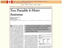 VE7CA reprint an interesting article taken from arrl antenna compendium. Two elegant practical and portable 6-meter gain antennas, a two-element quad and a tree-element Yagi antenna for 50 Mhz-6 meter band
 -
 This antenna project came out very nice. It's a rugged homebrew multi-band trap vertical antenna that works the 10, 15, and 20 meter amateur radio bands. The antenna can be mounted on the ground or on a mast. Mounted on the ground the antenna has a low take off angle for working DX. If mounted on a mast the antenna will acheive both a low angle as well as another radiation lobe that has a much higher take off angle.
 -
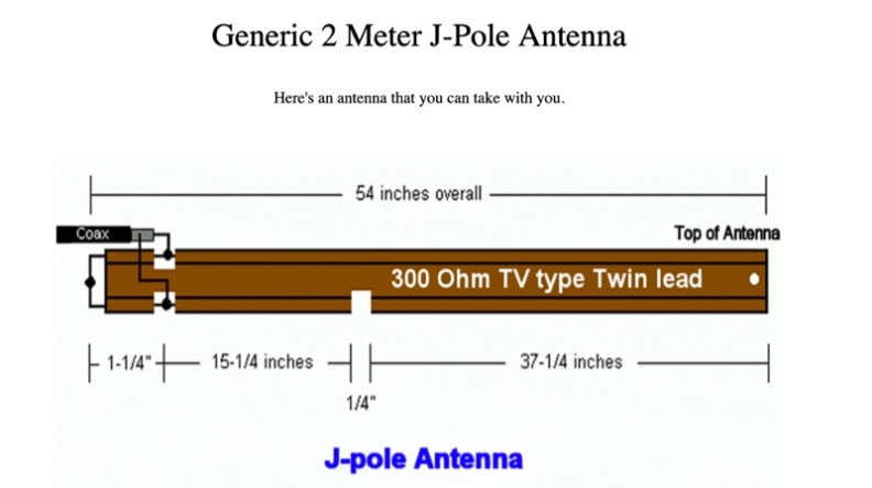 Here's an antenna that you can take with you. This is made from cheap flat 300 ohm TV antenna wire.
 -
 This is a resonant, half-wave, vertical antenna. It takes up little space in the back yard, was designed for operation on a single frequency 80 meter PSK net, and is reasonably inexpensive to construct by Chuck Hines, K6QKL
 -
 An experimental antenna similar to the TAK spiral antenna was evaluated for SWR response over the frequency range of 7.0 to 7.3 MHz, or the 40-meter band.
 -
 Described is a simple inverted-V antenna which, when used with a balanced ATU, can be used on all the main Radio Amateur HF bands (80, 40, 20, 15 and 10m). The cental support is made in such a way that the wire can be coiled up for storage when the antenna is taken down.
 -
 A simple antenna that can be erected very fast, only need one center support, and do not take up much storage room. Works from 40 to 10 meters band
 -
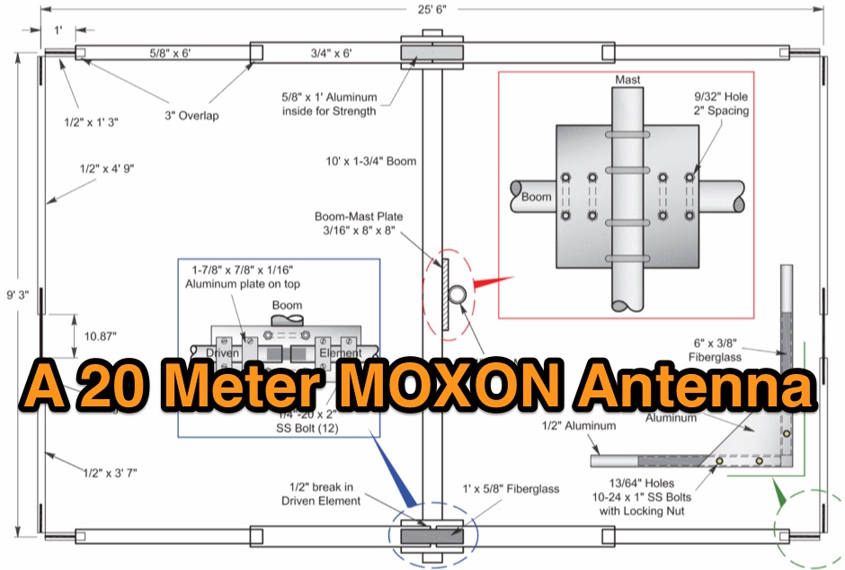 Moxons work great, and they take up less space than full size two element Yagis
 -
 Pickup truck stake pocket antenna mount by geotool
 -
 Connecting centre fed antennas, dipoles, yagis, rhombics, loops to coaxial cable, unless care is taken, it is not difficult to end up with feeder radiation resulting in power loss and the radiation characteristics changes
 -
 A 500-watt mobile antenna project details the conversion of an old 10m hamstick into a highly efficient, multiband "bugstick" for HF operation. The core modification involves replacing the original coil with 25 turns of 6 turns-per-inch, 1.5-inch diameter coil stock, fabricated from #14 wire. This design, intended for a 3-magnet mount on a vehicle cab, achieves resonance on multiple bands by shorting out specific turns on the coil, similar to a **bugcatcher** antenna. Measurements taken with an MFJ-259 analyzer on a GMC pickup show 0 turns shorted for 20 meters (14.2 MHz), 10 turns for 17 meters, 16 turns for 15 meters, 19 turns for 12 meters, and 23 turns for 10 meters. The construction emphasizes using UV-resistant tie-wraps and #14 solid wire with crimp lugs for robust RF connections, bypassing the fiberglass rod for current flow. A bonus section details a 40-meter version, utilizing 48 turns of 8 TPI, 2-inch diameter coil stock.
 -
 Some antenna manufacturers place baluns at the incorrect location in LPDA arrays. If we consider what the balun does we can see how the mistake occurs.
 -
 Accurately determining an antenna's feedpoint impedance is crucial for optimal performance, especially when experimenting with new designs or making adjustments. While SWR meters provide basic information, a full complex impedance measurement reveals the resistive and reactive components, which are essential for proper matching. Modern antenna analyzers, like the _Palstar ZM30_ or MFJ259B, simplify this task, but measurements taken through a transmission line require careful interpretation due to impedance transformation. This resource details a calibration method to precisely account for the effects of the feedline. It explains how a transmission line can significantly alter the measured impedance, illustrating this phenomenon with a Smith Chart example where an 80m antenna's [22 + j6] Ohms feedpoint impedance transforms to [82 + j45] Ohms after a 10m line. The guide demonstrates using a transmission line calculator applet, such as the one by W9CF, to reverse this transformation. It outlines the process of calibrating a specific length of RG174 coax, showing how an initial 26ft estimate was refined to **25.85ft** to accurately predict a known 22 Ohm load, significantly improving accuracy over uncalibrated results.
 -
 A simple and awesome wire monoband antenna, very usefull for portable and dxpeditions usage, consist of two elements, a driver and the reflector. This endfed halfwave gives a very low take off angle and is very suited for chasing DX.
 -
 The resource presents a detailed schematic for constructing a dual-band vertical antenna, specifically designed for operation on the 2-meter and 70-centimeter amateur radio bands. It illustrates the physical layout, critical dimensions, and component placement necessary for successful replication. Key elements such as the radiating elements, phasing sections, and feed point are clearly depicted, providing a visual guide for radio amateurs undertaking a homebrew antenna project. The diagram specifies the lengths for the VHF and UHF sections, indicating how these elements are integrated to achieve dual-band functionality from a single coaxial feedline. It also implies the use of common materials readily available to most experimenters, focusing on simplicity and effectiveness in its design. The visual format of a GIF image ensures direct access to the construction details without requiring extensive textual interpretation. This schematic serves as a practical reference for hams interested in building a compact, efficient vertical antenna for local and regional FM communications, offering a proven design for immediate implementation.
 -
 The X80 multi-band HF vertical antenna, a commercial iteration of the Rybakov design, exhibits a physical length of 5.5 meters, or approximately 18 feet, and is constructed from aluminum tubing. It operates as a non-resonant vertical, requiring an external antenna tuner for impedance matching across its intended operating frequencies. The antenna's design incorporates a 1:4 UNUN at its base, facilitating a nominal 50-ohm feed point impedance for the coaxial cable. Performance observations indicate effective operation on 40 meters, 20 meters, 15 meters, and 10 meters, with reduced efficiency on 80 meters and 160 meters due to its relatively short electrical length for these lower bands. Comparative analysis with a G5RV dipole and a half-wave end-fed antenna reveals the X80 offers a lower take-off angle, beneficial for DX contacts, particularly on the higher HF bands. Field tests conducted with an Icom IC-706MKIIG transceiver and an LDG AT-100ProII autotuner demonstrate the X80's ability to achieve acceptable SWR across 80m through 10m. The antenna's compact footprint and ease of deployment make it suitable for restricted spaces or portable operations, though its performance on 80 meters is noted as a compromise compared to full-size resonant antennas.
 -
 Spipral antenna principle by a concept of Bill Petlowany, K6NO. Tak Antennas are based on this principle, using spirals as dipole linear wires.
 -
 Constructing a compact directional antenna for the 17-meter band, this resource details the build process for a Moxon rectangle, a two-element Yagi variant with folded-back elements. It covers the antenna's evolution from the _VK2ABQ beam_ and provides specific dimensions for a version built using fishing pole whips. The content includes a discussion of the antenna's radiation pattern, feedpoint impedance, and its inherent front-to-back ratio, which is often superior to a standard two-element Yagi. Practical considerations for element spacing and material choices are also addressed, alongside a visual representation of the antenna's physical layout. Performance data presented includes a comparison showing the Moxon rectangle's **2.5 dB gain** over a half-wave dipole and a front-to-back ratio of **20 dB**. The resource also touches upon the antenna's relatively wide bandwidth for a two-element beam and its suitability for portable operations due to its compact footprint. It offers insights into optimizing the design for specific operating conditions and discusses the advantages of its lower take-off angle compared to omnidirectional wire antennas, making it effective for DX contacts on the 17-meter band.
 -
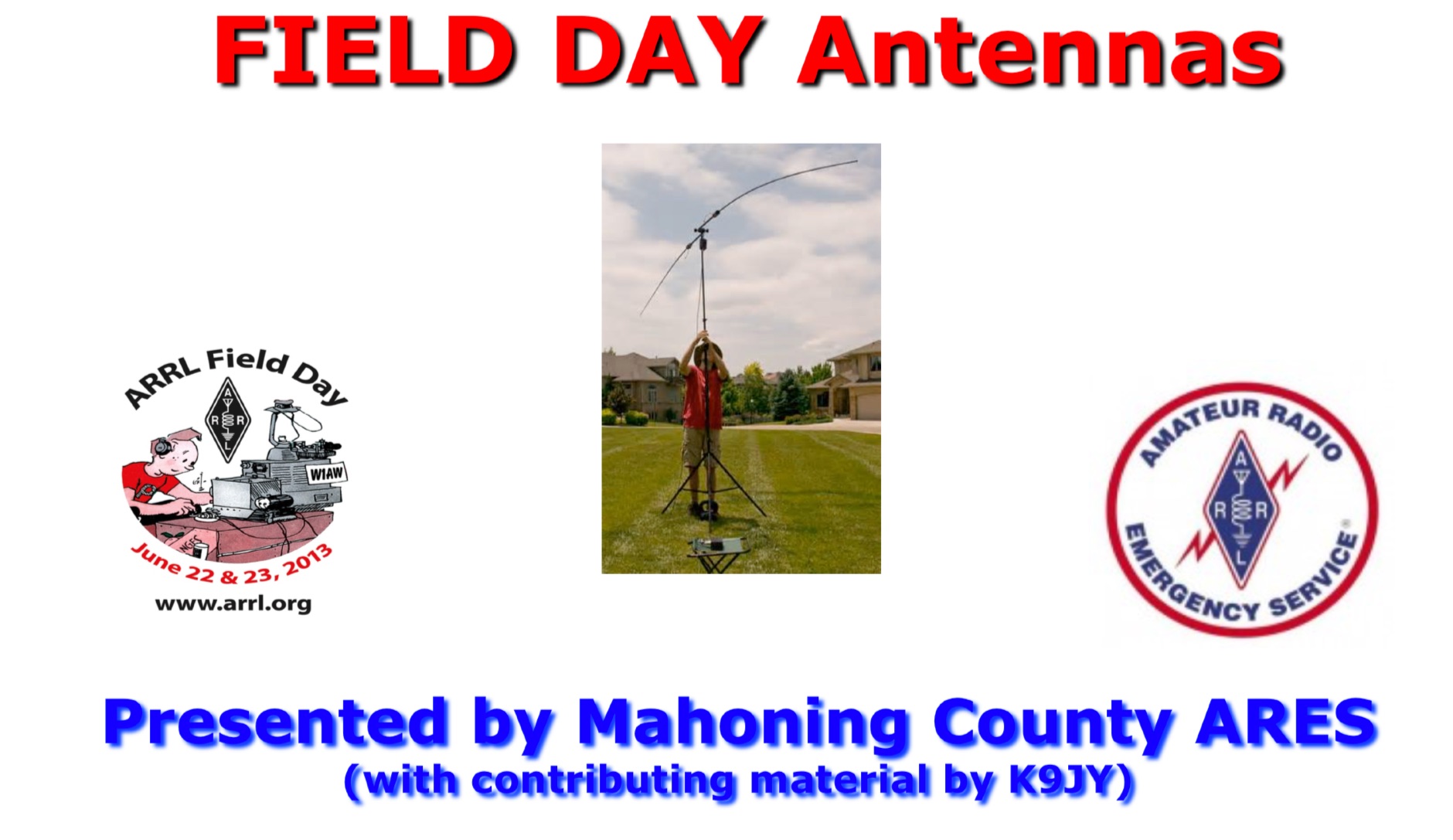 HF VHF UHF antenna ideas to be used for field days. All antennas are quick to set up and take down and offer proven performance and flexibility. Presentation offered by Mahoning Country ARES
 -
 An interesting presetnation full of usefull tricks to correctly design and build 23 cm Yagi using simple tools. The basic design of the antenna presented in this document is taken from the original DL6WU Yagi Design published in 1982
 -
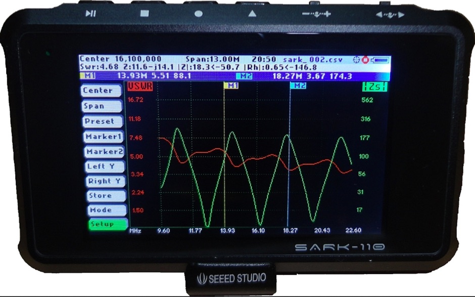 The SARK-110 is a completely new design concept for an Antenna Analyzer. This is a truly pocket size device, so you can take it anywhere. It offers a gorgeous 3" high-resolution, active-matrix color display that allows information-rich diagrams, works from 0.1 to 230MHz
 -
 Installing a mobile rig in a vehicle requires careful planning and execution to ensure optimal performance and safety. The process begins with selecting the right equipment, such as the ICOM IC706MKII for low bands and the ALINCO DR-610 for VHF/UHF operations. Proper mounting is crucial; both radios are strategically placed under the back seat of the Silverado, allowing for a clean installation while maintaining passenger comfort. The Hustler antenna, equipped with various resonators, ensures coverage across multiple bands, while the LDG automatic antenna tuner fine-tunes the match for efficient operation. A remote head for the tuner enhances accessibility, making adjustments easier while driving. Each step of the installation is documented to provide insights and tips for fellow operators looking to enhance their mobile setup. The experience shared here reflects practical knowledge gained through hands-on work, aiming to inspire others in the ham community to undertake similar projects.
 -
 A portable (15.5 foot diameter) NVIS loop for 3.5 to 7.3 MHz. Performs well at high and low takeoff angles, and has smaller footprint than most NVIS antennas.
 -
 The Shoddytenna is a 160 meters band vertical antenna intended for portable use. This antenna takes just 15 minutes to erect on site, can be carried by hand and is ideal for local groundwave work.
 -
 Designing and constructing a two-element receiving loop antenna array for HF operation involves specific considerations for achieving high directivity and noise reduction. This resource details a homebrew system comprising two 30-inch diamond-shaped loops, spaced 20 feet apart, which are fed through mast-mounted preamplifiers and passive signal combiners. The operational principle relies on adjusting phase delays between elements via precise _Belden 8241_ coaxial cable lengths, optimized for specific bands from 160m to 20m. Performance data, derived from _EZ-NEC_ modeling, illustrates consistent 90° azimuth-plane beamwidth and low take-off angles across the target bands, with _Receiving Directivity Factor_ (RDF) values comparable to a 300-foot Beverage antenna. The article presents detailed elevation and azimuth plots for 20m, 30m, 40m, 80m, and 160m, demonstrating the array's ability to provide strong response at low DX angles while also supporting _NVIS_ signals. Key components like the _DX Engineering RPA-1_ preamplifier and _DXE RSC-2_ signal combiner are discussed, alongside the importance of impedance matching to preserve antenna patterns. The construction emphasizes self-contained elements that do not require ground radials, offering a compact solution suitable for suburban environments and stealth installations, with a focus on optimizing receive performance independently from transmit antennas.
 -
 The Tri-pole antenna, a clever modification of a standard dipole, allows for dual-band operation by integrating a third element. This design effectively shortens the overall dipole length by 10 to 20 percent, simplifying antenna rotation and offering a compact footprint. KK4OBI's article delves into the operational principles, using a 6 and 10-meter Tri-pole as a primary example, and provides comprehensive instructions for constructing any Tri-pole antenna within the 6 to 15-meter range. Key to the Tri-pole's performance is its off-center feed, necessitating a common mode choke at the feed point for optimal tuning and reduced noise. The author outlines a methodical approach to determining element dimensions, starting with a vertical element frequency calculated as 0.47 times the sum of the desired upper and lower band frequencies. This calculation, along with K-values derived from trend lines, guides the initial lengths for the horizontal arms, demonstrating how a 10m-6m Tri-pole can achieve a total horizontal length 78% shorter than a conventional 10-meter dipole. Tuning and balancing are critical, with the article detailing adjustments to arm lengths and the vertical element to achieve balanced SWR values, as validated through 4NEC2 simulations. Radiation patterns are analyzed at various elevations, showing gains around 5.7 dBi and favorable take-off angles for DX contacts. Construction details specify aluminum tubing dimensions, U-bolts, and an SO-239 connector, emphasizing the importance of a ferrite-based choke for wideband operation.
 -
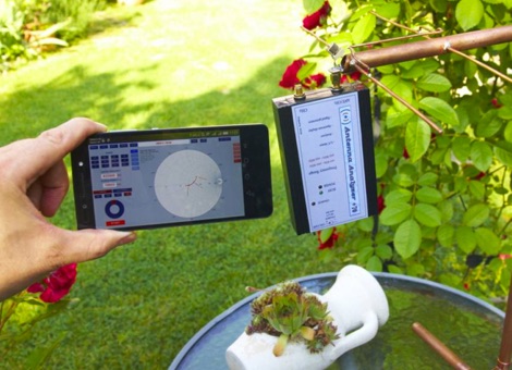 Antenna Analyzer plus 500 is a multifunctional measuring instrument, very useful for amateur radio activity. Its size allows you to easily take it for relocation as well. Frequency range: 100KHz - 500MHz. Access directly via WiFi. Includes a dual-channel signal generator
 -
 The Narrabeen JOTA and JOTI camp facilitates global communication for Sydney North Region Scouts and Northern Sydney Girl Guides, utilizing amateur radio and internet technologies. Participants engage in two-way radio contacts, often on **HF** bands, to connect with other scouting and guiding groups worldwide, fostering international goodwill and technical skill development. The event integrates both traditional **ham radio** operations and modern internet-based communication methods, providing a diverse experience for youth members. The resource outlines the specific activities undertaken at the Narrabeen site, including station setup, operating procedures, and the use of digital modes for JOTI. It highlights the educational aspects of the event, such as learning about radio propagation, antenna theory, and basic electronics, all within a structured camp environment. The page also provides logistical information relevant to the Australian context of the event.
 -
 This page describes a couple of parts box medicine bottle antennas that you can build. The ground side of the capacitor is soldered to the ground of the BNC connector. The positive side of the capacitor takes 5 turns around the toroid and is soldered back to itself. The center pin of the BNC connector takes 5 turns around the toroid and then continues on to the wire wound inductor. From there the antenna continues with an attached piece of wire.
 -
 You can bend the wires in a half-wave dipole so that it takes up less space, with minimal loss of efficiency.It is advisable to get the ends of the antenna as high as possible, especially if children and animals are kept in the area around the antenna, as there are very high tensions on the ends of the antenna during transmission! In Norwegian
 -
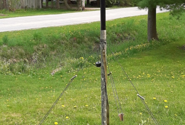 Supporting a telescopic fiberglass antenna pole for ham radio operation. Rather than cumbersome methods like using angle iron or PVC pipes, author employs lightweight tent stakes, toggles, and paracord to secure the pole effectively. With careful knot tying and simple materials, he ensures rapid deployment and stability even in windy conditions, offering a practical solution for outdoor antenna setups.
 -
 This antenna is designed for 40, 80 and 160 meters to complement a tri-band beam normally taken on DX peditions for 10, 15 and 20 meters, so six bands can be worked with only two antennas.
 -
 Constructing a 5-element quad antenna, the author aimed for low cost and simplicity, resulting in an effective design with 11 dBi gain and SWR of 2:1 or better across the 2-meter band. Using wood and dowels, the antenna costs under $8 and takes less than two hours to build with basic tools. The model predicts excellent performance, confirmed by ARRL Lab measurements. Practical field results demonstrate improved communication, even in simplex mode.
 -
 This project outlines the construction of a simple TEFV (Tilted End-Fed Vertical) antenna suitable for backyard or park installations. The design requires basic materials such as 100 feet of coated stranded copper wire, wood stakes, metal ground rods, a non-conductive fiberglass pole, and essential tools like wire cutters and a soldering iron. The antenna is supported by a 20-33 feet tall pole and includes a 9:1 unun for impedance matching and a resistor for tuning. Step-by-step instructions guide the assembly, from preparing the wire and pole to connecting the unun and resistor, ensuring a functional and durable setup for outdoor use.
 -
 What do amateur radio operators worldwide, think of their passion? What do we wish for? What are we frustrated about? How many of us are active, versus those that are taking a break? Do we have favorite radios, antennas, or even favorite cw paddles? Do we prefer one contest over another? The best way to find out is if we all participate in Ham Census. Join in and let all amateur radio operators know your thoughts "share your views" then you can find out what everyone else is thinking, in real time. Help shape the future of ham radio by participating in the world's most complete survey of amateur radio.
 -
 SWR Magazine is free montlhy ham radio online magazine published in English and Spanish. SWR Magazine presents a mix of analysis, hands-on experience, and technical insight for ham radio operators. Covering global radio trends, technical topics like antenna takeoff angle, operating practices outside the shack, reviews of radios, propagation. Explore innovative antennas, digital modes like RTTY, and historical radio origins. This issue bridges the past, present, and future of amateur radio, inviting readers to not just read, but experience and experiment with the content.
 -
 This presentation on antennas is a practical guide for amateur radio operators. The key takeaway is that the best antenna for your station depends on your constraints and goals. There is no magic solution and buying a wire antenna is not recommended as it might be expensive and not as effective. The presentation covers different antenna types including dipoles, verticals, Yagis and loop antennas. Important factors to consider when choosing an antenna include SWR, feeder types, and whether you need a balun. The author emphasizes that ATUs don’t improve a poor antenna and advises against obsessing over SWR readings.
 -
 This article discusses the evolution of portable amateur radio operations, focusing on optimizing backpack-carried equipment for outdoor use. The author shares his journey from using wheeled carts to developing an innovative backpack-mounted antenna system, emphasizing the transition from high-power (QRO) to low-power (QRP) operations to reduce weight. The piece details practical solutions for antenna mounting, equipment selection, and portable operations in challenging terrain, particularly along Ontario's Niagara Escarpment. The author's approach prioritizes mobility and functionality while maintaining effective radio communications in remote locations.