Search results
Query: turns ratio
Links: 33 | Categories: 0
-
 GM4JMU shortened dipole for 40 meters band. This article illustrates in detail how to build a resonant antenna for 7.030 MHz. Cut two 10.25-meter pieces of insulated wire, wind 40 turns of wire onto plastic tubing, and connect the wire to a central insulator using a choke balun built of RG174AU coax and a ferrite toroid. Once built, the antenna is adjusted by altering the wire length to produce the lowest Standing Wave Ratio (SWR) for best performance. The guide emphasizes careful building and adjustment for the best results.
 -
 Presents a practical design for a **crossed-dipole turnstile antenna** specifically engineered for 2-meter Amateur Radio Direction Finding (ARDF) events. The author, WB6RDV, details a robust, omnidirectional, horizontally-polarized antenna, addressing the international ARDF rules requiring such characteristics at a height of two to three meters above ground. This contrasts with the vertical polarization often used in Southern California, highlighting the design's adherence to specific event requirements. The electrical design employs a classic crossed-dipole with a 75-ohm phasing section, resulting in a slight impedance mismatch and an SWR of approximately 1.3:1 with a 50-ohm feedline. Construction utilizes readily available and inexpensive PVC plumbing components and 1/8-inch bronze welding rod for elements. The guide provides step-by-step instructions for mechanical assembly, including drilling element holes at precise 90-degree spacing and preparing the RG-179 matching section. WB6RDV shares insights from his own build experience, discussing the use of plated brass versus aluminum spacers for element attachment and the effectiveness of crimping as an alternative to soldering. The document also covers final assembly, including the integration of ferrite beads as a choke balun and options for weatherproofing and alternative mounting configurations, emphasizing the adaptability of the design for other VHF bands through scaling.
 -
 This drawing shows a simple 10 meter wire J-pole antenna designed for 28.4 MHz. It is a vertical, end-fed Zepp-style antenna made from common materials and intended for easy home construction. The main radiating element is a straight length of stranded copper wire, either 14 or 18 gauge, cut to about 16.5 feet. At the top, the wire is supported by an insulator, allowing the antenna to be hoisted vertically. The matching section is made from 450-ohm ladder line, approximately 7 feet 9.5 inches long, and shorted at the bottom. This matching stub transforms the impedance so the antenna can be fed with coaxial cable. The feed point is tapped about 6 inches above the bottom of the stub, with the shield and center conductor connected at the proper points. A choke balun is formed with five turns of RG-58 coax in a 4-inch diameter loop to help reduce unwanted RF on the feed line. The drawing notes that this antenna has about 0 dBd gain, similar to a dipole, but offers an omnidirectional pattern and low-angle radiation when installed high. Its main advantage is practical performance, simple construction, and effective coverage for 10 meter operation.
 -
 A rotary trapped-dipole for 17 and 20 meters, as described by IZ7ATH, presents a practical solution for multi-band HF operation. The author, Talino, recounts his experience building this antenna for IK7ZCQ, detailing the evolution from an initial concept involving a grounded-driven element and gamma-match to a direct-fed, non-grounded design. His pragmatic approach, adapting available materials, is evident throughout the construction narrative, particularly with the use of eight tapered aluminum pipes for the driven element. Construction specifics include precise measurements for the aluminum tubing, with diameters ranging from 30 mm down to 16 mm, and a critical note on reducing tip thickness for weight optimization. The _traps_, initially a concern, are fabricated using 8 turns of RG58 coax on a 27 mm support, tuned to resonate at 18.1 MHz using a dip-meter. Talino emphasizes sealing the traps with RF glue and PVC tape to prevent water ingress, a crucial step for longevity. Field test results, conducted on a 10-meter pole in a clear garden environment, showed an SWR of 1.2:1 on 17 meters and 1.5:1 at 14.200 MHz. While SWR varied slightly when installed at Mario's QTH due to nearby objects, the antenna's performance remained commendable. The final half-dipole length is 46 cm for the 18 MHz tips, and the total weight is under 6 kg, with potential for further reduction.
 -
 A 2-meter Turnstile antenna, detailed for amateur satellite communication, offers a straightforward build for those looking to engage with orbiting transponders. The author, WB8ERJ, shares his personal design and construction methods, emphasizing the antenna's simplicity and effectiveness for LEO (Low Earth Orbit) satellite work. This design provides a circularly polarized signal, crucial for mitigating _Faraday rotation_ and signal fading often encountered with linearly polarized antennas when tracking satellites. Construction involves readily available materials like PVC pipe and copper wire, making it an accessible project for many hams. The article includes practical advice on element spacing and feed point considerations, drawing from the author's hands-on experience in the shack and field. It highlights the antenna's utility for receiving signals from various amateur satellites, including the popular AO-91 and AO-92. The Turnstile's inherent omnidirectional pattern in the horizontal plane, combined with its circular polarization, yields consistent signal reception, often resulting in **stronger decodes** and **more reliable contacts** compared to basic dipoles or verticals.
 -
 Modifying the _ICOM IC-706MKII_ transceiver for out-of-band transmit capability involves specific surface-mount device (SMD) removal on the main circuit board. This procedure enables transmit functionality from 0.5 MHz to 200 MHz, excluding the commercial FM-Wide broadcast band, significantly expanding the radio's operational frequency range. The modification requires careful handling of small components and a fine-tipped, low-wattage soldering iron. Prior to beginning, all programmed memories and initial setup configurations must be noted, as the modification process will erase them. The instructions detail the necessary tools, preparation steps, and the precise location of the two SMD diodes to be removed. These diodes are situated near an oblong crystal can and a test point labeled _CP3_ on the main board. Successful completion returns the unit to its default configuration, necessitating manual reprogramming of memory channels and initial settings. This project is suitable for operators with experience in SMD work and fine soldering.
 -
 Constructing a compact, two-band magnetic loop antenna for HF operation, especially from constrained locations like a balcony, presents unique challenges. OK1FOU's design, inspired by DJ3RW's 50 MHz loop, addresses these by employing an unusual side-fed configuration and placing the symmetric, two-section variable tuning capacitor at the bottom of the loop, directly connected to the coax shield. The article provides specific material recommendations, including two 1-meter wooden pales and about 3 meters of thick loudspeaker cable, noting the high current (60A at 100W) in the loop. Construction steps detail forming two turns with a 5 cm gap, using a GDO to pre-tune the open loop to a frequency slightly above the desired highest band, and then integrating the tuning and coupling capacitors. For 10/14 MHz, an open loop resonance of 16-17 MHz is suggested. Practical experience with the 10 MHz band from a third-floor balcony in Prague (JO70GC) shows a 1:1 SWR across most of the band without an external ATU. While DX traffic was modest due to the urban environment, QSO examples with RA6WF, LA6GIA, G0NXA, and LZ1QK on 10 MHz are provided, demonstrating its operational capability.
 -
 The QRP choke balun described utilizes a high permeability ferrite rod and RG-174 coax, aiming to present high impedance to common-mode currents across the HF spectrum. The construction involves winding as many turns of RG-174 as possible around the ferrite rod, then encapsulating the assembly with hot glue. This design prioritizes maximizing inductance to suppress unwanted shield currents, particularly in unbalanced antenna configurations. While the balun's effectiveness is subjectively reported as good, a potential design consideration involves the dielectric properties of the hot glue. This material could increase turn-to-turn capacitance, potentially reducing the balun's performance at higher HF frequencies, though this specific aspect has not been formally tested by the author, _AA5TB_. The project serves as an illustrative example of a practical, junk-box construction rather than a rigorously engineered solution. Photographs detail the evolution of the balun, from the initial winding process to its integration within a _B&W dipole center insulator_ and final camouflaged assembly.
 -
 Operating a ZS6BKW antenna often involves understanding its lineage from the _G5RV_ design, with specific modifications by ZS6BKW to optimize performance on several bands. Through computational analysis and field measurements, the antenna's dimensions were refined to allow operation on 10, 12, 17, 20, and 40 meters without an antenna tuner. For 80, 30, and 15 meters, a tuner is necessary, though efficiency on 30 and 15 meters is noted as not particularly high. The physical configuration consists of two 13.755-meter radiating elements fed by a 12.20-meter section of 450-ohm ladder line. Tuning the antenna on the 20-meter band is critical, and any deviation in the ladder line's characteristic impedance necessitates recalculating the element lengths. The design is also referenced in the 12th edition of _Rothammel's Antennenbuch_, page 219. Proper common mode current suppression is crucial at the transition from ladder line to coaxial cable. This can be achieved with a common mode choke, such as several turns of coax wound into a coil or over a ferrite toroid like an Amidon T130. While a 1:1 balun is an option, it may introduce issues.
 -
 A 500-watt mobile antenna project details the conversion of an old 10m hamstick into a highly efficient, multiband "bugstick" for HF operation. The core modification involves replacing the original coil with 25 turns of 6 turns-per-inch, 1.5-inch diameter coil stock, fabricated from #14 wire. This design, intended for a 3-magnet mount on a vehicle cab, achieves resonance on multiple bands by shorting out specific turns on the coil, similar to a **bugcatcher** antenna. Measurements taken with an MFJ-259 analyzer on a GMC pickup show 0 turns shorted for 20 meters (14.2 MHz), 10 turns for 17 meters, 16 turns for 15 meters, 19 turns for 12 meters, and 23 turns for 10 meters. The construction emphasizes using UV-resistant tie-wraps and #14 solid wire with crimp lugs for robust RF connections, bypassing the fiberglass rod for current flow. A bonus section details a 40-meter version, utilizing 48 turns of 8 TPI, 2-inch diameter coil stock.
 -
 The Resonant Feedline Dipole (RFD) HF antenna design utilizes a single piece of coaxial cable and a stranded wire section, forming a 1/4-wavelength radiator. This configuration, based on a 1997 ARRL Handbook design (page 20.17), functions by RF traveling on the inside of the coax shield and returning on the outside, creating the second half of the dipole. A choke wound into the feedline prevents RF current from flowing back down the feedline. Construction details include using RG-58a/u coax for a 75m version, with a 1/4-wavelength section of stranded wire soldered to the center conductor. The document provides choke dimensions for RG-213, RG-8, and RG-58 coax across 3.5 MHz to 28 MHz, specifying cable length and number of turns. Dipole dimensions are also tabulated for frequencies from 3.6 MHz to 28.4 MHz, listing overall length and individual leg lengths. Field tests included deployment near Bryson City at 5 feet off the ground and as a sloper during WCARS Field Day in Asheville, yielding successful local and regional contacts.
 -
 Demonstrates the construction of a 144 MHz turnstile antenna, detailing its design for omnidirectional, horizontally polarized VHF operation. The resource outlines the physical dimensions and materials required, including specific lengths for the radiating elements and the use of _RG-58_ coaxial cable for phasing. It covers the assembly process, emphasizing the critical spacing and connection points to achieve the desired radiation pattern and impedance matching for the _2-meter band_. The article presents measured _SWR_ performance across the 144-146 MHz segment, showing a low SWR of 1.2:1 at 144.5 MHz, which is suitable for general VHF use. It compares the turnstile's performance to a 9-element Yagi, noting the turnstile's advantage in providing consistent signal strength from all directions without requiring a rotator. Practical application for local FM simplex and repeater operations is implied, offering a simple yet effective antenna solution for fixed or portable stations.
 -
 One point eight MHz to 30 MHz is the operational bandwidth for this 4:1 Ruthroff voltage balun, designed to interface an unbalanced T-Match network with a balanced antenna system. The project details the construction using a _T200-2_ powdered iron toroid core, tightly wrapped in PVC electrical tape for insulation, and wound with 17 double bifilar turns of 1.25mm enamelled copper wire. This outboard balun offers flexibility, allowing hams to trial various baluns based on antenna system and impedance characteristics, rather than integrating it directly into the tuner. The resource includes a schematic of the balun, a wiring diagram showing winding connections, and a table suggesting alternative toroid cores like the T80-2 or T400-2 with corresponding winding counts. Component sourcing is straightforward, listing items such as the _Amidon_ T-200-2 core, SO-239 connector, and a sealed polycarbonate enclosure from Jaycar. Performance evaluation was conducted using an _AIM 4170C_ antenna analyser, demonstrating efficient 1:4 voltage transformation across the specified HF spectrum. Further efficiency tests involved measuring RF power loss at various frequencies, revealing minimal loss—less than 0.7 dB from 3.6 MHz to 30 MHz, and only 2.0 dB at 1.8 MHz. These measurements, performed under ideal 50-ohm conditions, confirm the balun's effectiveness as a low-loss interface for multi-band antenna systems. The page also links to several other balun and unun projects, including 1:1 current and voltage baluns, and 9:1 voltage ununs, providing a broader context for impedance matching solutions.
 -
 A fractional bandwidth of up to 30:1 characterizes spiral antennas, making them highly effective across a very wide frequency range, often from 1 GHz to 30 GHz. The resource details two primary types: the **Log-Periodic Spiral Antenna** and the **Archimedean Spiral Antenna**, defining each with specific polar functions and illustrating their planar configurations. It explains that spiral antennas are typically circularly polarized, with a Half-Power Beamwidth (HPBW) of approximately 70-90 degrees, and a peak radiation direction perpendicular to the spiral plane. The content elaborates on critical design parameters affecting radiation, including the total length (outer radius) for lowest frequency, the flare rate ('a' constant) for optimal radiation versus capacitive behavior, the feed structure (often an infinite balun) for high-frequency operation, and the number of turns (typically 1.5 to 3 turns). It also discusses the theoretical impedance of 188 Ohms for Log-Periodic spirals, derived from Babinet's Principle, noting actual impedances are often 100-150 Ohms. The article presents a simple construction method for an Archimedean spiral, demonstrating VSWR and efficiency measurements. Measurements from a constructed spiral antenna show a VSWR that is fairly constant across the band, albeit with a mismatch loss of about 3 dB. The antenna efficiency remains around -5 dB (31.6%) across its operating range, indicating a decent wideband radiator despite opportunities for optimization.
 -
 Decoding NOAA APT weather satellite images is achieved with a homebrew receiver and a Turnstile Cross Dipole antenna, feeding data to a Pentium-3 500MHz PC running Windows XP and the WXTOIMG program. This setup, operated by VU2IIA in Mumbai, India, focuses on capturing and processing signals from NOAA satellites to generate visual weather data. The blog documents the technical aspects of constructing the receiving station, including antenna design and receiver integration. It provides insights into the practical challenges and successes of amateur satellite reception, specifically for Automatic Picture Transmission (APT) signals. Operational details cover the software configuration and image processing workflow necessary to transform raw satellite data into usable weather imagery. The content serves as a practical guide for radio amateurs interested in satellite meteorology.
 -
 Designing and constructing portable wire antennas for HF operations, this resource explores several configurations including the _foldback dipole_ for space-constrained setups and an inductively shortened dual-band dipole for 20m and 40m. It details the calculation of inductance for shortened elements, providing a Visual Basic 6.0 program screenshot that illustrates determining coil parameters like turns and length for a **25.5 uH** inductor. The document emphasizes practical considerations such as adjusting wire lengths for optimal SWR, noting that a dual-band dipole achieved SWR below 2:1 on both 20m and 40m, with careful adjustment bringing it under 1.5:1. Further, the resource describes a half-wave antenna matched with a coaxial stub, a method often referred to as the _Fuchskreis_ in German amateur radio circles, to transform the high feedpoint impedance to 50 Ohms. This monoband solution, for a 20m application, uses a stub length of **2.98m** (0.216 lambda multiplied by coax velocity factor) and a shorted stub of approximately 48cm. The coaxial stub design is highlighted for its resilience to ground proximity, allowing it to be rolled up or laid on the ground with minimal SWR impact, making it highly suitable for portable QRP operations.
 -
 The resource details the construction of a multiband trap-style Inverted-V antenna designed for operation on 3.5 MHz, 7 MHz, 14 MHz, 21 MHz, and 28 MHz. It presents specific winding data for the traps, including the number of turns, wire gauge, and coil former dimensions, crucial for achieving resonance on the target bands. The document provides a parts list and a diagram illustrating the antenna's physical layout and trap placement. It outlines the process for building the traps using PVC pipe formers and specifies the required capacitor values for each trap. The design emphasizes a practical approach to achieving multiband operation with a single feedline, a common goal for HF operators with limited space. The document includes a table with antenna segment lengths for each band, allowing for precise replication of the design. It also offers insights into tuning and adjustment, ensuring the antenna performs optimally across the designated amateur radio bands.
 -
 Presents a construction project for a 1:1 current balun, specifically detailing the _Sorbie Balun and Bottle Choke_ design. The resource outlines the winding technique, employing 4+4 turns of mini coaxial cable on a large ferrite core, and provides insights into the physical assembly. It includes specific material recommendations, such as the type of ferrite and coaxial cable, crucial for achieving the desired impedance transformation and common-mode current suppression. The content covers the practical steps involved in building the balun, from preparing the coaxial cable to securing the windings on the ferrite toroid. It also discusses the integration of the balun into an antenna system, emphasizing its role in maintaining pattern integrity and reducing RF interference in the shack. The resource offers a clear, step-by-step approach, making the project accessible for homebrewers. Illustrations and photographs accompany the text, visually guiding the builder through each stage of construction. The article concludes with performance expectations and considerations for deployment, ensuring the constructed balun functions effectively across the intended frequency range.
 -
 Lido Radio Products specializes in **no-holes mounting solutions** for a wide array of mobile electronic devices, including amateur radio transceivers, smartphones, and tablets. Their product line features cup holders, vent mounts, and window mounts, designed to secure equipment without permanent modifications to a vehicle's interior. The company supports various brands such as Icom, Yaesu, Kenwood, Motorola, Hytera, and Vertex, catering to both amateur radio operators and land mobile users. My own experience with similar mounting systems for mobile operations confirms the utility of a secure, non-invasive setup. A stable mount prevents equipment from becoming a projectile during sudden stops or turns, a critical safety consideration for any mobile station. Lido's focus on specific radio brands suggests a tailored approach to fit and function. They also provide individual parts to customize existing mounts, allowing operators to adapt solutions to unique shack or vehicle configurations. This modularity is a significant advantage for hams who frequently reconfigure their mobile setups or integrate new gear.
 -
 K1JJ presents a compilation of insights regarding vertical radial ground systems, specifically applied to 160m vertical arrays. The resource details 19 distinct observations and recommendations, emphasizing that ground radials primarily reduce ground losses rather than influencing pattern formation. It explains that RF current flows inefficiently through average soil, necessitating copper radials to create a low-resistance path back to the antenna base. The content suggests that **50-60 radials** are generally sufficient to achieve optimal efficiency, with diminishing returns beyond that number, and that radials should be laid on the surface for best performance. The discussion also addresses practical aspects such as wire gauge, installation techniques using 'U' shaped staples, and methods for connecting radials in multi-element arrays. It highlights the importance of radial length, stating that 1/4 wave radials are a crucial minimum, and that for 160m, radials should be at least _100 feet_ long. The resource critically examines the efficacy of elevated radials versus ground radials, noting that while a few elevated radials may suffice for VHF, HF applications, particularly on 160m, require extensive ground radial systems to efficiently collect RF currents in the near field. It also touches on the impact of radial systems on parasitic elements and the significance of symmetrical radial patterns for minimizing losses. Further practical advice includes wire type recommendations, proper soldering and weatherproofing techniques for radial connections, and considerations for integrating steel towers into the ground system. The author shares personal experience with installing 60 quarter-wave and half-wave radials under each of three in-line verticals, expressing satisfaction with the results.
 -
 A quad turnstile consists of two cubical quad loops oriented in a diamond configuration and angled 90 degrees apart from one another with both diamonds sharing the same top and bottom points
 -
 The MFJ-971 portable antenna tuner, as stock, lacks a bypass switch and sufficient inductance for efficient 1.8 MHz operation. This modification addresses these limitations by integrating a DPDT switch for direct signal bypass, enhancing operational flexibility. Furthermore, the guide details the addition of a T130-2 iron powder toroid, wound with **29 turns** of enamelled copper wire, to augment the tuner's internal inductance. This increases the maximum inductance from approximately 17µH to around **27µH**, enabling effective impedance matching on the _160-meter band_. The modification involves cutting the wire after the 'L' tap on the original inductor and inserting the additional toroid, ensuring the entire original coil plus the new inductance is engaged when 'L' is selected. This preserves the functionality of other inductance settings while extending low-band performance. The article also highlights a potential RF burn hazard from the variable capacitor nuts on the MFJ-971, even at QRP power levels.
 -
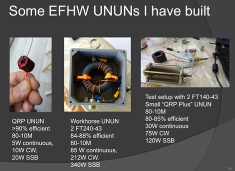 A very well done presentation about End-Fed Half-Wave antennas. This PDF document contains a summary of experiences in how to build custom EFHW antennas. Includes an interesting comparison table of UnUn configurations with recommended toroids, Wire size, turns and capacitors. An useful recap on common errors in building homebrew EFHW Ununs completes the document.
 -
 Constructing an End-Fed Half-Wave (EFHW) antenna offers a practical solution for HF operators seeking a multiband wire antenna without the need for extensive radial systems. This design typically employs a high-impedance transformer at the feed point, matching the antenna's inherent high impedance to a 50-ohm coaxial feedline. The article specifically details a 2012 approach, focusing on a transformer with a 49:1 turns ratio, which is a common configuration for EFHW antennas. The resource outlines the construction of a wire element cut for a half-wavelength on the lowest desired band, with specific coil arrangements enabling operation on harmonically related bands such as 40m, 20m, and 10m. It discusses the physical dimensions and winding details for the matching transformer, often utilizing a ferrite toroid core to achieve the necessary impedance transformation. The content provides insights into the operational principles and practical considerations for deploying such an antenna, including methods for tuning and optimizing performance across multiple amateur radio bands. While acknowledging that the presented information from 2012 may be superseded by newer insights, it serves as a foundational reference for understanding EFHW antenna theory and construction.
 -
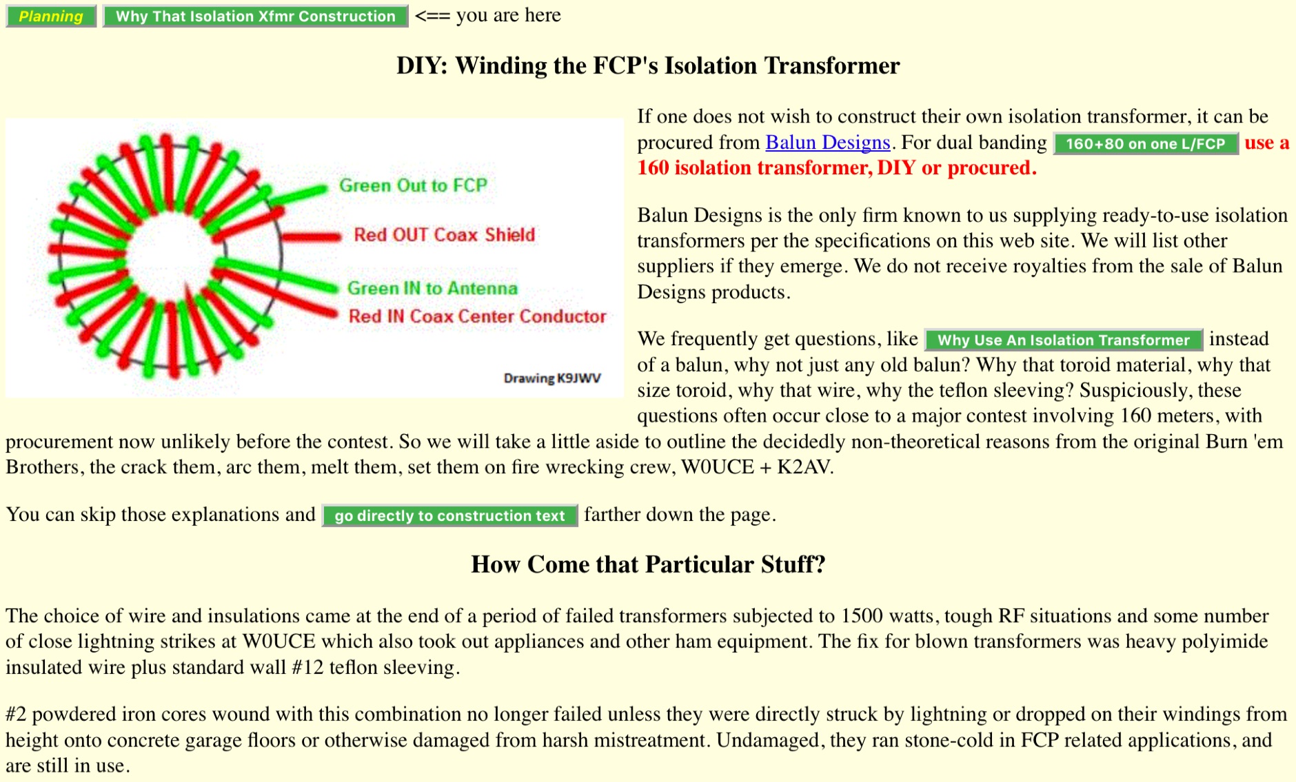 Article about isolation transformer construction to perform optimal impedance matching. Winding the FCP isolation transformer, includes interesting table for Winding Turns and Lengths and Core Configurations for T300 T200 T400 toroids
 -
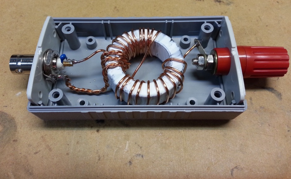 An end-fed half wave antenna matching unit made of 3:24 turns ratio on a FT140-43 toroid with a 150pF capacitor across the input.
 -
 A 60-foot available space, for example, might necessitate a shortened multiband dipole array to cover 80, 40, and 15 meters effectively. This resource details the construction of such an antenna, combining full-size and coil-loaded dipoles on a single feedline. It addresses the common challenge of fitting multiple HF bands into restricted physical footprints, providing practical guidance for hams with smaller backyards or portable operations. The core of the offering is an interactive calculator that determines required loading coil inductance and dipole lengths for various amateur bands from 160m to 10m. Users input their available space, and the tool provides dimensions, coil turns, and an efficiency rating (Good or Fair) based on the antenna's electrical length relative to a quarter-wavelength. It also suggests suitable _PVC_ pipe diameters for coil forms. The article further illustrates a center feed-point assembly using an 18-inch section of 2-inch _PVC_ pipe, detailing eye-bolt spacing and coaxial connector installation. It emphasizes the importance of adequate spacing between parallel dipoles and offers customization options for the feed-point, including the addition of a _Balun_ for improved feedline isolation.
 -
 Presents Wayne Kerr Electronics, a manufacturer specializing in precision component measurement products. The company offers a range of LCR meters, impedance analyzers, and transformer test systems designed for various applications in electronics manufacturing and research. Specific product lines include the 3260B Precision Magnetics Analyzer, which measures inductance, capacitance, and resistance with high accuracy, and the 6500B series of LCR meters, capable of testing components across a broad frequency range up to 120 MHz. The 3255B and 3265B series provide solutions for transformer and inductor testing, including turns ratio, leakage inductance, and inter-winding capacitance measurements. These instruments are utilized in quality control, component characterization, and production line testing, ensuring performance and reliability in electronic circuits. Wayne Kerr's offerings support engineers and technicians in verifying component specifications.
 -
 This blog post details the construction and usage of a 4:1 current balun, using two FT240-31 ferrite cores and 12 bifilar turns. It clarifies common misconceptions about using 4:1 baluns with G5RV antennas and ladder-line to coaxial cable connections. M0PZT emphasizes the importance of proper measurements and the limitations of internal baluns in manual antenna tuners. Detailed instructions and considerations for winding and deploying the balun are provided, along with advice on choosing suitable cores and wire for various power levels and frequency ranges.
 -
 A dual band X-frame wire antenna made using 4 turns for response down to 3 MHz or so, and 2 turns (switched) for response up to around 18 MHz. The loop configurations are tuned using common eBay 365 pF tuning caps.
 -
 Ferrite E-cores offer a practical solution for constructing baluns, especially when connectors are already mounted on cables. These cores, commonly used in mass-produced pulse transformers, allow for multiple turns without dismounting connectors, making them ideal for control and power supply cables. The material of E-cores is generally suitable for common mode baluns up to 15 MHz, providing a cost-effective option for amateur radio operators. E-cores can often be sourced from old switch-mode power supplies, adding to their appeal for those looking to utilize existing resources. A notable example involves a balun on a USB cable using a Ferroxcube E 32x16x9, 3F3 core with four turns, secured by three cable ties. This setup demonstrates the ease of construction and stability achievable with E-cores. Another example features a balun with eight turns of shielded cable with RCA connectors on the same core, achieving 140 uH inductance at low frequencies. The impedance plot for this configuration is measured between the shield ends, illustrating the effectiveness of E-cores in practical applications. The article includes detailed figures and descriptions, providing valuable insights into the construction and application of baluns using ferrite E-cores. These examples serve as a guide for amateur radio enthusiasts looking to enhance their setups with cost-effective and efficient solutions.
 -
 The LKJ Wednesday Night Special Antenna, designed by John Whiteman K5LKJ, is a compact 50-foot coil-loaded dipole for 80-meter operation, ideal for space-limited hams in residential areas. Using two 1-inch diameter PVC coils with 87 turns of #16 magnet wire each—placed 10 feet from the center—it tunes to 3.910 MHz for local nets like BVARC Rag Chew. Constructed with #14 wire, ceramic insulators, and Mini-8X feedline, it handles 1000W, performs well at low heights for NVIS, and requires a tuner for bandwidth. Collaborative tuning by club members ensured success.
 -
 This resource details the construction and performance of a compact broadband magnetic loop antenna designed for portable receiving applications with devices like the _ATS MiniRadio_. The antenna utilizes approximately 3 meters of 0.5–1 mm copper wire wound in two turns on a rhomboidal wooden frame, measuring 50 cm by 70 cm. It connects via a modified 9:1 unun, where the primary center tap is isolated from ground to improve common-mode noise rejection. The design provides untuned operation across a frequency range from the longwave band up to approximately 25 MHz. Performance characteristics include observable directivity for noise suppression and the ability to connect directly to a radio or via a 50 coaxial cable for remote operation. The article specifies the unun's 3:1 turns ratio and its SMA output for connectivity. The methodology focuses on practical construction and observed reception quality.