Search results
Query: watt amp
Links: 71 | Categories: 0
-
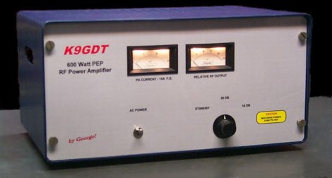 Schematics plans by K9GDT and all infos to build a 600 Watt HF Amplifier. The amplifier uses four Motorola MRF150 50 volt TMOS power FETs configured in push-pull/parallel and biased for class AB linear operation.
 -
 Presents _Henry Radio Inc._ as a manufacturer of solid-state RF power amplifiers, detailing their capabilities across HF, VHF, and UHF bands. The company designs and builds custom amplifiers tailored for various applications, including amateur radio, commercial broadcasting, military, scientific, and industrial uses. These amplifiers are manufactured in the USA, emphasizing domestic production. Beyond amplifier manufacturing, the resource highlights Henry Radio's role as a distributor for _Bird RF Test Equipment_, including wattmeters, dummy loads, and attenuators. It also mentions _Tohtsu Coaxial Relays_ and a range of miscellaneous amplifier parts and electronic accessories, providing a broader scope of communication equipment offerings. Additionally, the site describes a trunking two-way radio system operating on the 450-476 MHz band, covering significant portions of Los Angeles and Orange County. This service caters to professional dispatch needs for ambulances, taxis, and other commercial entities, requiring no long-term contracts.
 -
 Manufacturer of amplifiers, antenna switches antenna Tuners, wattmeters and relay buffers, amplifier accessories, antennas and tubes and parts
 -
 This compact little amplifier is the brain-child of Pat Murdoch, ZL1AXB, in Auckland, New Zealand. It is only 11" wide, 4" high, and 9" deep. Operates for 40, 20, 17, 15, 12, and 10m
 -
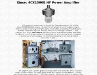
 Use 4CX10000D / 8171, RF output power of 11 KW in key-down carrier on all bands. Power was measured with a Bird 4712 wattmeter and a 25 KW slug
 -
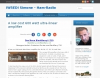
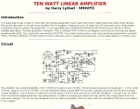
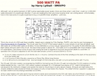 500W Power Amplifier by Harry Lythall - SM0VPO
 -
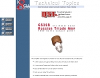 50 MHz 1500 Watt Russian GS35B amplifier. Well documented. Complete construction details,pictures,schematics, and more.
 -
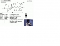
 This article describes a 10 watt linear amplifier that is capable of delivering over 15 watts into 50 ohms and uses cheap plastic transistors that are used in CB equipment. by Harry Lythall - SM0VPO
 -
 Antennas, Filters, accessories, wattmeters, tuners and amplifiers.
 -
 This is a project to develop an Open Source reference design for a 1500 watt solid state linear amplifier for 10 through 160 meters by K6IF
 -
 The project details modifications to an ARK-40 QRP CW transceiver kit, specifically replacing its original thumbwheel frequency selectors with a **BASIC STAMP BS-II microcontroller** and an optical shaft encoder. The redesigned control circuitry outputs a BCD code to the ARK-40's synthesizer, enabling more convenient knob-type tuning. This modification significantly alters the user interface, moving from discrete frequency selection to continuous tuning. Operating frequency is presented on an LCD readout, offering two distinct display modes: a "bandspread dial" mode that simulates an analog dial scrolling across the display in 1 kHz increments, and a conventional digital readout with 100 Hz resolution. Pushing the main tuning knob toggles between these modes, providing both rapid band traversal and fine-tuning capabilities. The software for the BASIC Stamp is written in P-Basic, addressing the challenge of accurate analog dial simulation. Physical modifications include fabricating a custom PC Board for the STAMP, mounting it with an L-bracket to the optical encoder, and creating a new front panel. The front-mounted speaker was relocated to accommodate the new tuning knob and display, transforming the **ARK-40 transceiver** into a more user-friendly rig with its built-in CW keyer and 5 watts of power.
 -
 A 144 MHz kilowatt amplifier project details the construction and performance of a high-power VHF linear using the GU74b tetrode. This Russian tube, equivalent to the Svetlana 4CX800, is noted for its conservative datasheet ratings, performing closer to 800-1000W anode dissipation in practical applications. The design prioritizes compactness and achieves 1.2 kW output with only 20W of drive power, demonstrating a 70% efficiency at 2.5 kV plate voltage. The amplifier has been successfully deployed in demanding _EME_ (Earth-Moon-Earth) operations since June 1994. Challenges encountered during development included achieving stability with a grid-1 input configuration. The author, _CT1DMK_, opted not to publish the full design due to its complexity, suggesting it might be difficult for less experienced builders to replicate successfully. However, he invites direct contact for those with specific interest in the design. Future plans include a "144MHz GS35b compact amplifier" project, promising another kilowatt-plus design. This resource offers insights into high-power VHF amplifier construction and the practical application of specific power tubes.
 -
 The NCDXF/IARU International Beacon Project schedule provides precise transmission start times for 18 beacons operating on 14.100 MHz, 18.110 MHz, 21.150 MHz, 24.930 MHz, and 28.200 MHz. Each beacon transmits every three minutes, cycling through its callsign at 22 WPM followed by four one-second dashes. The initial callsign and first dash are sent at 100 watts, with subsequent dashes at 10 watts, 1 watt, and 100 milliwatts, enabling **propagation analysis** across varying signal strengths. The schedule lists the minute and second within each hour for the first transmission of each beacon on its respective frequencies. This resource allows **DXers** and **contesters** to accurately predict beacon transmissions for real-time propagation assessment. For example, 4U1UN transmits first at 00:00 on 14.100 MHz, followed by VE8AT at 00:10, and W6WX at 00:20, continuing the sequence. The page also notes recent hardware upgrades, such as the installation of IBP 2.0 controllers with Icom 7200 radios at some sites, and provides status updates for beacons experiencing hardware failures or those not recently heard, aiding in troubleshooting and managing expectations for monitoring.
 -
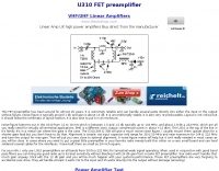 This FET preamplifier has been around for almost 25 years. It is extremely reliable and can handle several watts directly into either the input or the output without failure.
 -
 Solid State and TWT Amplifiers From 1 MHz to 40 GHz with Power Levels from .1 mil Watt to 2.5 Kw
 -
 1500 Watt HF power amplifier
 -
 Constructing a high-power solid-state amplifier for HF operations presents unique challenges, particularly when aiming for significant output like 600 watts. This project details an amplifier design employing **Motorola MRF150** FETs, a common choice for their robust performance in RF power applications. The design emphasizes achieving substantial power output, a critical factor for effective DXing and contesting, where every decibel can make a difference in signal propagation and readability. While specific circuit diagrams or construction details are not directly presented on the current page, the mention of MRF150 FETs points towards a design that would typically involve push-pull configurations, impedance matching networks, and robust power supply considerations to handle the high current demands. Such amplifiers are often built with an eye towards linearity and efficiency across the HF bands. Amateurs pursuing similar high-power solid-state projects often share insights on thermal management, intermodulation distortion, and component sourcing, all vital for a stable and reliable amplifier capable of delivering 600 watts into a proper antenna system.
 -
 Details a practical QRP wattmeter construction, leveraging a simplified SWR meter design by JA6HIC. The project focuses on a forward-only power measurement circuit, providing a functional instrument for RF power levels from milliwatts up to 5 watts. It maintains a 50-ohm input and output impedance, suitable for typical QRP transceivers and antenna systems. The resource includes the schematic for the "VSW" (Very Simple Wattmeter) and outlines a six-step alignment procedure. This calibration process involves using a known RF source up to 5W, setting full-scale deflection, and marking power increments. It also addresses minimizing frequency effects on readings with a 100pF trimmer capacitor, noting that measurement error is highest at the lower end of the scale. Construction notes mention using a piece of RG-213 coaxial cable for the inductance and coupler, with the wattmeter assembled in early 2003. The author provides an example measurement showing 0.8W into a dummy load and 1W into a 3-element beam.
 -
 An RF power amplifier, providing 7 Watts output in HF bands, schematic by ON6MU
 -
 VU2RAR basic VHF power amplifier suitable for 144-146 Mhz output power can vary from 3 to 25 Watts.
 -
 Allow 9 bands and 1300 Watt output on the TL-922 amplifier with this document by PA0FRI
 -
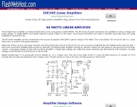 The 60 Watt linear amplifier is simple all solid state circuit using power mosfet IRF840.
 -
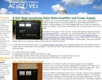
 G3WZT John Matthews project of a 600 Watt solid state linear amplifier for the 6 meters band
 -
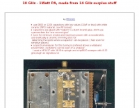 1 watt amplifier for 10 ghz made from surplus stuff
 -
 A solid state linear based on EB104 Motorola Engineering Bulletin by Helge Granberg. It uses 4 MRF150 FETs in push-pull parallel to acheive 600 Watts from about 6 Watts drive
 -
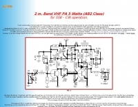 A VHF power amplifier made with two cheap RF transistors, 2N3924 as driver and a BFS22A for final stage, giving an unexpected output power of 7-8 watts maximum
 -
 A lower power desktop linear with integrated 120vac power supply. This, very compact, dual 811 version will deliver about 300 watts output. Covers all bands including WARC bands.
 -
 The UK amateur radio licensing scheme features three distinct tiers: Foundation, Intermediate, and Full, each granting specific operating privileges. For instance, the **Foundation Licence** permits a maximum of 10 watts output power on most allocated bands, with restricted band access. The Intermediate Licence allows up to 50 watts, while the **Full Licence** grants access to the maximum UK legal power limits and all available amateur radio band allocations. UK call sign prefixes and formats provide insights into the licensee's class and the approximate issuance date. For example, M3, M6, and M7 prefixes with three letters denote Foundation Licences issued from 2002, 2008, and 2018 respectively. Intermediate Licences, often starting with "2E0" or "2E1" followed by three letters, were issued from 1991 onwards. Full Licences encompass a broader range of prefixes like G2, G3, G4, G0, and M0, with varying letter counts indicating different historical license classes and issuance periods, such as G3 plus three letters issued between 1946 and 1971. Special prefixes like GB are reserved for repeaters, beacons, data mailboxes, and special event stations, with specific numerical sequences (e.g., GB3 for repeaters, GB7 for data repeaters/mailboxes) indicating their function. Optional prefixes such as GC, GD, GI, GM, and GW denote specific UK countries (e.g., Wales, Isle of Man, Northern Ireland, Scotland, England) and can also signify club stations.
 -
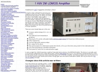 2 meter kilowatt linear amplifier
 -
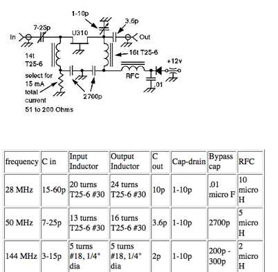
 20 Watt Power Amp for Softrock or for QRP transceivers by M0RZF
 -
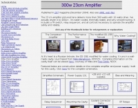 The 23 cm amplifier pictured here delivers more than 300 watts with 10 watts drive.
 -
 Plans and hex code for an RF wattmeter based on an Analog Devices AD8307 log amplifier.
 -
 This document details the design and construction of the PA70H, a 50-watt RF amplifier for the 70MHz (4-meter) amateur radio band. Built around the Mitsubishi RD70HVF1 MOSFET transistor, the amplifier delivers 45-55W output with 3-5W input power while operating on 13.8V DC at approximately 7-8A. The PCB design incorporates multiple protection circuits including overcurrent, SWR, and temperature control. The amplifier features various control modes including GND PTT, +13.8V PTT, and RF VOX. Two versions are available: PA70HLI (requiring 100mW input with additional driver) and PA70H (for 3-5W input). The comprehensive documentation includes circuit diagrams, assembly instructions, and performance data showing successful operation from both 100mW and 3.5W input sources.
 -
 This article loaded with nice pictures and schematics, describes a 160-10 meter linear amplifier that uses a pair of 3-500Z triode power tubes. It was designed and constructed by William Moneysmith, W4NFR. The amplifier features fast warm up and 1500-Watt RF output with 100-Watts of drive.
 -
 Extremely reliable FET preamplifier can handle several watts directly into either the input or the output without failure
 -
 1500 watts PEP output from a Kenwood TL-922 amplifier requires careful attention to parasitic suppression and component selection to ensure stability and longevity. This resource critically examines common modifications, often based on anecdotal evidence rather than sound engineering principles, that can degrade performance or introduce new issues. It highlights how replacing aged components often gets misattributed to the efficacy of unnecessary modifications, leading to widespread misinformation within the amateur radio community regarding amplifier stability. The article details specific, effective modifications for the TL-922, such as shortening anode-to-chassis and anode-to-grid paths to improve VHF stability and efficiency. It addresses issues like incorrect capacitor types in the tank circuit, inadequate grid grounding, and poor RF sheet metal design, providing practical solutions like adding direct ground connections for the plate tune variable capacitor. The author also discusses proper parasitic suppressor design, emphasizing the importance of lead length and component selection for optimal performance and harmonic suppression, contrasting these with less effective or detrimental 'magical suppression kits'.
 -
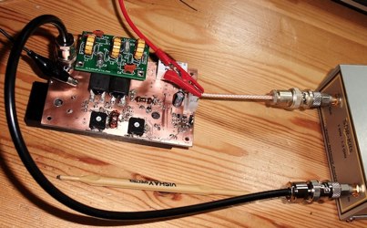
 The resource details the construction of a homebrew 50-watt FET amplifier, based on Don W6JL's _QST Homebrew contest_-winning design from 2009. It functions as an afterburner for QRP transceivers, providing a **12dB** power lift. The amplifier utilizes IRFZ24N FETs and covers the 80, 40, 30, and 20-meter bands, with the 20m LPF extending to 17m. Key technical aspects include an FT37-43 transformer for the input network, a relay-switched 3dB pad for lower bands controlled by an _Arduino Nano_, and an RF-actuated T/R switch. The LPF board integrates four relay-switched filters rated for 50 watts, using capacitors with a minimum 250VDC rating. Performance measurements indicate a power gain ranging from **4.4dB** on 20m to 8.1dB on 80m, with a required drive power of approximately 5 watts. The article also discusses thermal management, current limiting considerations, and component sourcing.
 -
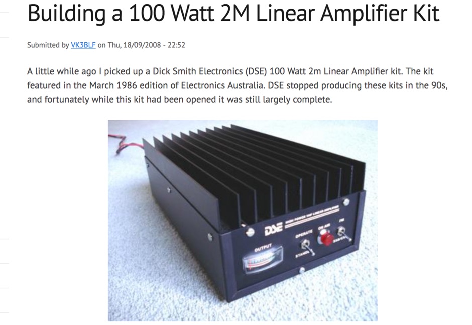 Article about assembling of a Dick Smith Electronics (DSE) 100 Watt VHF Linear Amplifier kit.
 -
 Here is a simple, self-contained beacon which can run a few milliwatts or as much as a watt depending on choice of amplifier and supply voltage.
 -
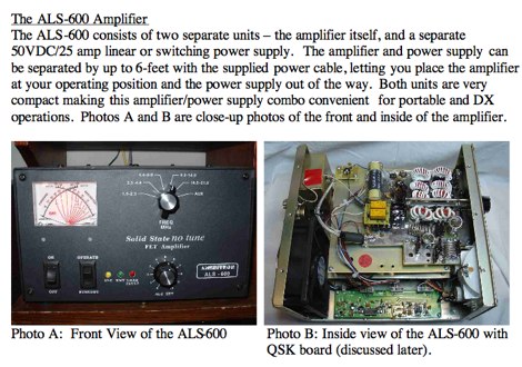 The Ameritron ALS-600 600-Watt HF Power Amplifier review by AD5X
 -
 AL-811 and AL-811H specifications and information about this 600-800 Watt ham radio ower amplifiers
 -
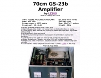 1500 watts of RF output on the 70cm band requires robust amplifier design, a challenge addressed by this project featuring the GS-23b / 4CX1600U Svetlana tube. The resource details the construction of a high-power UHF amplifier, providing insights into component selection and layout necessary for stable operation at these frequencies and power levels.
 -
 Constructing a high-power 70cm solid-state amplifier presents unique challenges, particularly when aiming for 500 watts output using modern LDMOS devices. This resource details the author's experience building a 70cm amplifier based on a _Freescale MRFE6VP5600H_ transistor, initially from an RFHAM kit. It meticulously outlines the necessary modifications to achieve advertised performance, including optimizing input and output matching, correcting bias circuitry, and ensuring proper output balun connections for stability. The author shares specific adjustments, such as trimming the prototyping board for better transistor fit, drilling additional mounting holes for improved heat sinking, and replacing original matching capacitors with a single _20pf MIN02 metal mica_ for superior output. A critical fix involved jumpering gate decoupling pads to balance the push-pull transistor halves, which increased output to 580W and improved IMD. The resource also highlights a crucial correction to the output balun connection, initially reversed in the _Dubus_ article schematic, which resolved intermittent stability issues. Test results are provided, showing input power, output power, and drain current at 50V, demonstrating the amplifier's performance after modifications. This practical account offers valuable insights for hams undertaking similar high-power UHF amplifier projects, especially those working with LDMOS devices and kit-based constructions.
 -
 This online project guide details the construction of a homebrew boom microphone system. It details the assembly of a microphone shell from a 3/4" PVC pipe section and an end cap, requiring a drilled hole for a snug fit of the electret or condenser mic element. The internal wiring schematic specifies a **2.2 K** resistor and a **47 uF** polar capacitor for signal conditioning, with a circuit diagram provided for integration with IC-706 series transceivers. The guide outlines the use of CAT-5 cable for internal connections, incorporating strain relief at the rear of the mic shell, and an inline 3.5 mm jack to facilitate an external _PTT_ line, designed for a foot-mounted switch. Further construction involves fabricating a microphone shock mount from a 2-inch PVC connector, detailing the creation of four "fingers" and the insertion of screw-eyes for attaching elastic bands, which are twisted 180 degrees for tensioning and vibration isolation. A foam wind screen is also incorporated into the microphone assembly, secured with adhesive. The boom arm itself is repurposed from an articulated architect lamp, with the original lamp assembly converted into a **60 watt** resistive load for testing power sources. Microphone cabling is secured to the boom arm using wire ties, ensuring sufficient slack at hinge points to maintain articulation. The boom base is mounted to a bookshelf, requiring specific positioning to achieve proper microphone placement in front of the operator. Performance evaluation of the microphone system is conducted through on-air audio signal reports from other amateur radio operators. DXZone Focus: Online Project Guide | Boom Microphone Construction | Electret Mic Element | PTT Line
 -
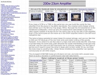 A 200 Watt amplifier for 23 cm band
 -
 160-10 Meters 1500 Watt Amp - W4NFR
 -
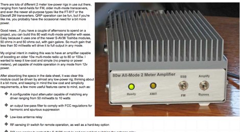 80 watt multi-mode amplifier using one of the newer S-AV36 Toshiba modules. Less than 50 milliwatts will drive it to full output in any mode.
 -
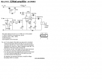
-
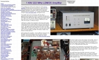 222 MHz kilowatt linear amplifier
 -
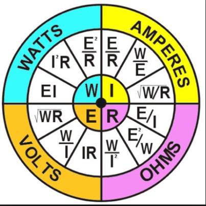 Both Watts and Volt-Amperes are units of measurement for electrical power. Learn what is the difference