Search results
Query: rf antenna
Links: 787 | Categories: 17
Categories
- Antennas > End-Fed > End Fed Half Wave Antenna
- Radio Equipment > HF YAGI Antennas
- Shopping and Services > Accessories
- Radio Equipment > HF Portable Antenna > Buddipole
- Antennas > Feed Lines > Choke
- Radio Equipment > HF Vertical Antenna > Cushcraft R5
- Antennas > EH
- Radio Equipment > HF Vertical Antenna > GAP Titan
- Technical Reference > Grounding
- Manufacturers > Test Equipment > Impedance Analyzers
- Antennas > Theory > Impedance matching
- Antennas > OCF
- Manufacturers > Remote Control
- Antennas > Repair and Maintenance
- Technical Reference > Test Equipment
- Software > Vector Network Analyzer
- Manufacturers > Wattmeters
-
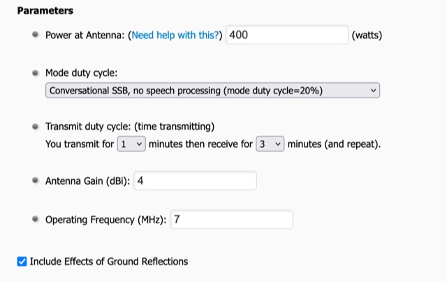 To use the RF Exposure Calculator, fill-in the form with your operating power, antenna gain, and the operating frequency. Depending on how far above ground the RF source is located, you might want to consider ground reflections too.
 -
 The multiband tuned doublet, or center-fed Zepp, is a simple and efficient HF antenna that operates effectively across most amateur bands using a balanced parallel-wire feedline and antenna tuner. Unlike coax-fed dipoles, it tolerates impedance mismatches with minimal loss. By selecting suitable feedline and dipole lengths, one can achieve stable multi-band operation. While it doesn’t match monoband Yagis, it offers excellent performance, low cost, and broad coverage. Its radiation pattern and efficiency vary with frequency, but it remains a practical and versatile solution for HF operators.
 -
 The Smith Chart, named after its inventor Phillip H. Smith, is a graphic tool used to solve transmission line problems in the field of ham radio operations. By using the Smith Chart, ham radio operators can determine the feed point impedance of an antenna, design impedance-matching networks, and optimize power transfer between a source and its load. The chart consists of resistance and reactance circles, providing a visual representation of complex mathematical relationships related to transmission line operations. Understanding and utilizing the Smith Chart is essential for hams looking to enhance the performance of their RF circuitry.
 -
 This page provides information on designing a lightweight Moxon antenna for the upper HF bands and VHF. The Moxon antenna is a compact version of a 2-element Yagi with folded elements, offering good forward gain and a high front-to-back ratio. It is designed for a single band with a feed-point impedance close to 50 ohms. Hams can orient the antenna horizontally or vertically, with polarization following the configuration, affecting radiation patterns. The page allows users to generate radiation pattern plots, VSWR charts, antenna currents diagrams, and Smith charts for their antennas on different ground types, helping them understand antenna performance in the field.
 -
 Learn how to build a simple tuned loop antenna for the AM broadcast band to improve the performance of your radio receiver. Discover how to construct a loop antenna with readily available materials, such as balsa and basswood, without the need for specialized woodworking tools. Follow step-by-step instructions to create a portable loop antenna that offers good gain and directivity, ideal for pulling in weak stations. Enhance your Ultralight DX'ing experience and explore the world of FSL antennas through this practical DIY project.
 -
 This page allows hams to design a vertical-plane delta-loop antenna for a single amateur HF band in different configurations. By choosing different feed-point positions, operators can observe variations in polarization properties, radiation patterns, and feed-point impedances. Users can generate radiation pattern plots, VSWR charts, antenna current diagrams, and Smith charts for their antennas over various ground types. Through adjusting the antenna's physical dimensions and refreshing the plots, hams can gain insights into the antenna's performance in the field. The page also discusses how elevation radiation patterns may change based on the antenna configuration and feed-point position.
 -
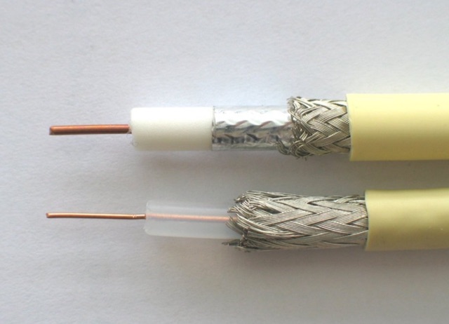
 Learn how to build a portable receiving antenna for the 160 meter band. This guide provides detailed instructions on constructing a loop antenna using a coaxial cable RG-316 with SMA connectors. The antenna weighs 1.7 kg and has dimensions of 2m in height and 1.892m in width. The wooden frame consists of four 0.945m long pieces and two 1m long pieces. Perfect for hams looking to enhance their 160m band reception during travel or portable operations.
 -
 The article describes a high-gain, compact beam antenna design for the 2-meter band (144-146 MHz). The NSH 4x4 Boomer is a 4-element antenna that is mounted on a 4-foot boom with an 8.2 dB gain, 1.2:1 SWR, and a front-to-back ratio of 18 db. It is designed for mobile operations and little area, making it perfect for field usage such as disaster management. The design employs regularly spaced parts with a straightforward gamma match for tuning, and the construction materials include a square boom and polished aluminum tubes. In local and portable tests, the antenna worked regularly, achieving contact distances of up to 15 kilometers.
 -
 This comprehensive three-part guide examines baluns (balanced-to-unbalanced devices) and their critical role in ham radio antenna systems. The author explains how baluns prevent common-mode currents on feedlines, which can distort radiation patterns and cause unwanted RF in the shack. Various balun types are analyzed, including coiled coax chokes, ferrite-core designs (W2DU), and toroidal-wound versions (Guanella/Ruthroff). Construction techniques for 1:1, 4:1, 6:1, and 9:1 current baluns are provided with practical guidance on wire selection, winding methods, and ferrite core properties. The article emphasizes that proper balun implementation is essential for optimal antenna performance, especially with directional arrays.
 -
 This article details the author's process of designing and building a trap dipole antenna for the 17, 12, and 6-meter amateur radio bands using a Yaesu FT-450 transceiver. The antenna incorporates parallel-tuned circuit traps to enable operation across multiple bands without switching aerials. Key construction details, including coil and capacitor specifications, are discussed, along with the testing results, which include successful long-distance communications on the 50 MHz band. The article highlights the flexibility of home-built antennas and provides insights for amateur radio enthusiasts looking to optimize multi-band performance.
 -
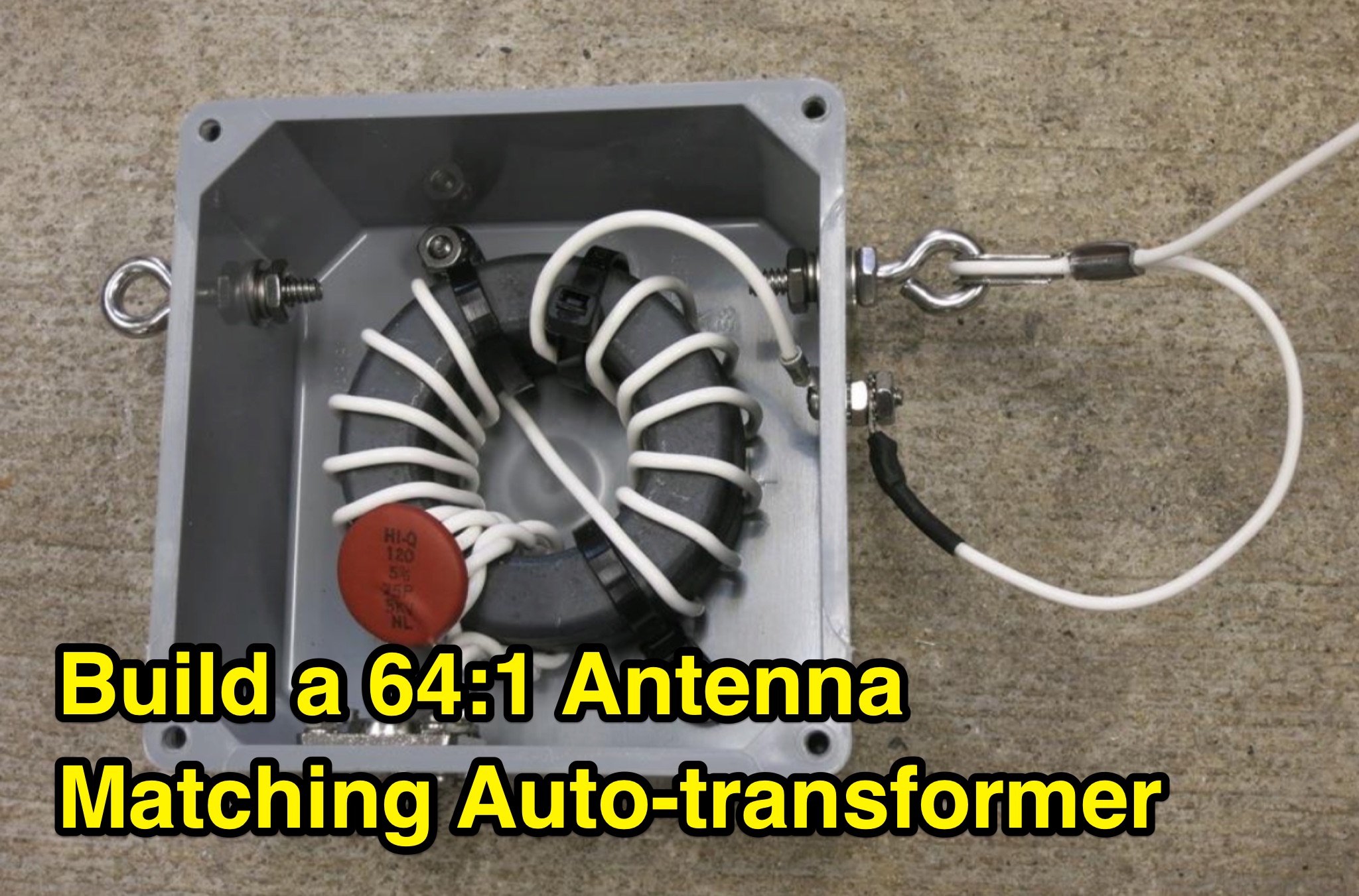 This PDF document provides information on a 64 to 1 antenna matching auto-transformer for ham radio operators. It likely includes details on how to build or use this specific type of antenna matching device, which can be helpful for hams looking to optimize their antenna setup. The document may contain technical specifications, diagrams, and instructions on how to properly implement the auto-transformer. Overall, it serves as a useful resource for hams interested in improving their antenna performance and signal transmission.
 -
 After a storm damaged the antenna, W6AER replaced it with a pre-made capacitance hat from DX Engineering. Using hose clamps and conductive grease, he ensured durability. Experimenting with radials and a coil, he aimed for better performance and resilience.
 -
 Antenna patterns are all about interference. Presentation on wire antennas for HF bands. Dipoles, horizontal and vertical dipoles, effects of ground on radiation patterns, multi-band wires antennas. Knowing what you should expect from the radiation patterns for waves on your wires will help you choose what will work best for your needs. The principles of interference can lend insight into what to expect from a wire antenna.
 -
 This blog post by VE3VN discusses the design and performance of a 40-meter reversible Moxon antenna. The antenna provides coverage between southeast to west by default, with the ability to reverse for coverage from east to northwest. The post explains how the antenna performs well in various directions, focusing on the Caribbean, South/Central America, the US, and Europe. Detailed measurements and design considerations are shared, highlighting the accuracy of the model and the critical importance of coil inductance. The post also mentions the use of NEC5 for accurate modeling. Overall, this detailed discussion provides valuable insights for ham radio operators looking to optimize their antenna setup.
 -
 Andrew Georgakopoulos, SV1DKD, modeled the End-Fed Half Wave (EFHW) antenna using MMANA-GAL software. He evaluated the EFHW-8010-2K from Myantennas.com for field operations, comparing it to random wires, OCFD, and dipole antennas. His results showed similar performance to OCFD, confirming EFHW's practical feeding advantage but with potential high-voltage risks at the feed point
 -
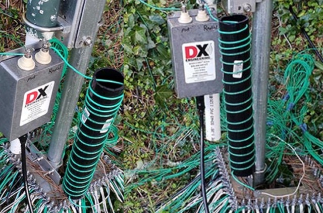
 The author explores enhancing the performance of a 7-meter fiberglass squid pole wire antenna for amateur radio. The wire, resonant at 10MHz, poses impedance challenges on various bands. Experimenting with direct coax feed and UN-UN transformers, the LDG Z11-Pro2 auto-tuner is found effective but may show deceptive SWR readings. The author employs adjustable UN-UN ratios and introduces a custom "porcupine" coil to optimize the antenna's efficiency.
 -
 This page provides detailed information on the 4DX directional wire beam antenna designed by LZ1AQ, LZ1ABC, VK6LW, and DD5LP. It explains how to create this antenna for single or multiple bands using four separate sloping wires. The page includes instructions on achieving directionality, gains, and F/B ratios, as well as generating radiation patterns, VSWR charts, antenna currents diagrams, and Smith charts. It is a valuable resource for hams interested in building and optimizing their own directional wire beam antennas for improved performance and long-distance contacts.
 -
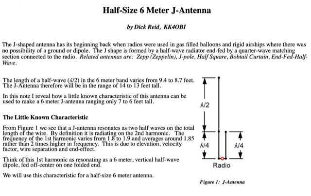 How to use a little known J-antenna characteristic to reduce a conventional 14 foot antenna to 7 feet. Perfect 50 Ohm match, same gain, no radials.
 -
 Building an efficient antenna begins with selecting the right aluminum stock. This article provides a comprehensive guide to sourcing aluminum materials for antenna construction. It covers different aluminum grades, their tensile strengths, tempering options, and their suitability for various antenna components. The article also recommends reputable suppliers in the UK, making it a valuable resource for antenna builders seeking durable and high-performance materials.
 -
 The feed line (also called the transmission line) is the RF power conduit between your radio and your antenna. The quality of your feed line is critical to your station. ARRL Article that explains differences among various commonly used feed line systems
 -
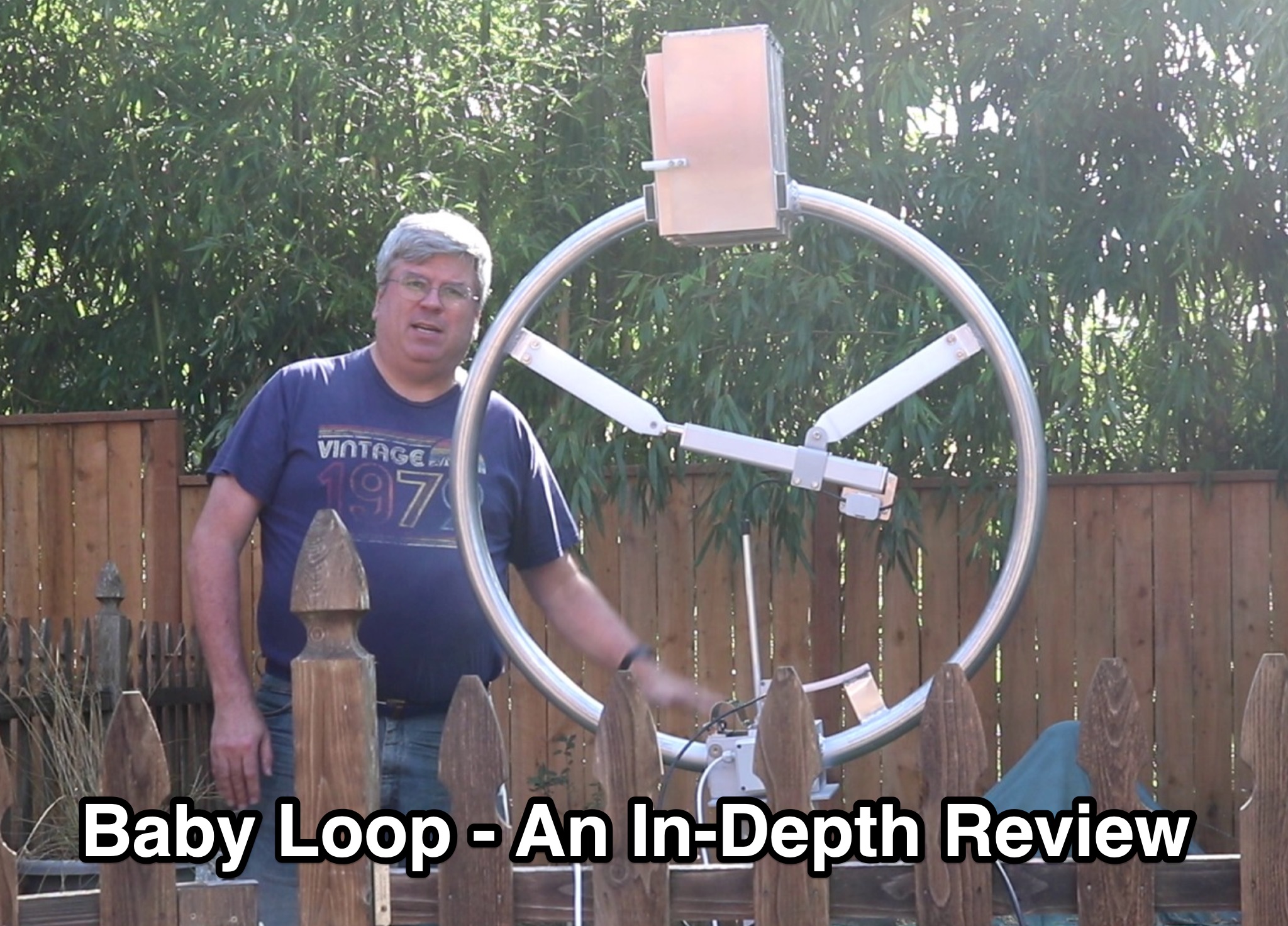 This article provides an in-depth review of the Ciro Mazzoni Baby Loop Ham Radio Antenna. The author, a ham radio operator, compares this magnetic loop antenna with his usual End Fed Half Wave antenna, discussing the performance and installation considerations. The post explains the concept of loop antennas, resonating frequencies, and the benefits of using a small loop antenna with a capacitor for optimal operation. If you are looking for information on magnetic loop antennas and their effectiveness in restricted spaces, this review offers valuable insights and practical experiences for ham radio operators.
 -
 Explore the design and testing of a cage dipole antenna for 6 meters. Through innovative construction, witness a remarkable 77% increase in bandwidth and improved impedance characteristics.
 -
 A vertical delta loop is a practical antenna for low bands, popular for its simple design requiring just one support. Its shape, an equilateral triangle in free space, yields optimal gain and radiation resistance. Deviating from this shape lowers performance. The delta loop can be polarized either horizontally or vertically based on the feed point location. In vertical polarization, it acts as two quarter-wave verticals with the baseline feeding one side. This design minimizes radiation from the baseline while maintaining effective operation.
 -
 The Dipole Bazooka Antenna for 40 meters is a popular choice among amateur radio operators. Its design allows for easy construction using materials like RG58 coaxial cable and PVC. Measurements are calculated using specific formulas; for instance, at a frequency of 7,100 MHz, the total length is approximately 19.74 meters. This antenna offers a performance range of 97% to 99%, with an impedance of 49 to 52 ohms. Additionally, it can handle up to 1 kW of power and requires no modifications for connection.
 -
 Phased array antennas are composed of multiple individual antenna elements that can have their phase and amplitude controlled to steer the main beam direction in real-time. They are used in radar, communications, and electronic warfare, and offer improved gain and reduced side lobes. A comprehensive document on Phased Arrays include techniques to increase the Antenna Gain and change the Radiation Pattern
 -
 The Portable EFHW antenna for the 40, 20, 15, and 10-meter bands utilizes a broadband transformer with a 1:49 ratio, designed on a PCB by either Jan or DL2MAN. The design incorporates an **FT114 core**, offering an alternative to the FT82 core. The antenna requires precisely 20.5 meters of DX Wire Ultralight for optimal performance. Additional components include DX Wires "Dyneema" 1mm rope and 1mm bricklayers string for structural support. The SWR plot indicates performance at two elevation heights: 5.5 meters (blue line) and 4 meters (yellow line), demonstrating optimization for low-elevation portable use without poles. The antenna's components, including spool and rope tensioners, are available for 3D printing, with spool dimensions scaled to 130% for a length of approximately 110mm. The design emphasizes simplicity and portability, suitable for field deployment.
 -
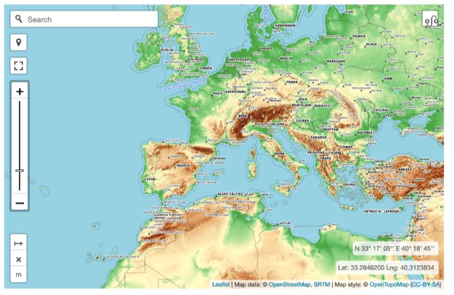 Online interactive elevationmap can help radio amateurs by predicting signal propagation, optimizing antenna placement, planning coverage, ensuring line-of-sight, mitigating interference, and enhancing emergency communication. T
 -
 This project describes the construction of a W3HH (T2FD) antenna for HF bands (3-30 MHz). While less efficient than a tuned dipole, it offers broad frequency coverage with a maximum SWR of 3.4 and reduces QRM (noise) significantly. On the 80-meter band, it shows slightly weaker signals than a dipole but with improved signal-to-noise ratio. The design includes non-inductive resistors, a 13:1 balun, and a "frog ladder" transmission line. Though not a high-performance antenna, it is compact and versatile, making it ideal for wide-band HF communication. Article in French
 -
 Learn how to design a Hentenna antenna, a portable asymmetrical double-loop antenna ideal for amateur HF or VHF bands. This page provides details on constructing and optimizing the antenna for maximum performance in DX communications. Discover how altering the antenna's vertical feed section can adjust the VSWR resonant frequency and how changing the support pole's position can alter the beam direction. Originally developed by Japanese 6-meter operators, the 'Hentenna' offers a unique design that allows for horizontal polarization when vertically oriented. Explore radiation patterns, VSWR charts, and antenna currents diagrams to optimize your antenna's performance for long-distance contacts.
 -
 A C-Pole Antenna for QRPxpeditions describes a DIY C-Pole antenna designed for QRP (low-power) expeditions, inspired by KF2YN’s ground-independent vertical model. After adjustments, it achieved a 1:1 SWR at 14.060 MHz, rising to 2.5:1 at 14.35 MHz. A choke balun, comprising 15 turns of RG8X around a 4†can, was essential for optimal performance. Compact and self-supporting, the antenna enables reliable communication with minimal setup. Contacts included stations across the U.S., and even a 4,600-mile connection to Spain using only 5 watts.
 -
 PH0NO conducted field tests comparing a mobile antenna (DX-UHV) to an end-fed half-wave wire. Results on 20m showed the end-fed wire outperforming the mobile antenna, with a significant difference in signal strength. On 40m, the end-fed wire surpassed the mobile antenna in spots and reach. While the mobile antenna is more practical, the end-fed wire offers superior performance. Further testing is planned.
 -
 This page provides guidance on designing an End-Fed Half-Wave (EFHW) or Random-Length antenna for amateur HF bands, such as 80 or 40 meters. The content explains how to optimize the antenna for multi-band use and match it to a 50-ohm system using an unun. Hams can generate radiation patterns, VSWR charts, and antenna current diagrams for their customized antenna designs. Understanding how antenna dimensions affect performance is essential for successful field operations. The page caters to ham radio operators looking to build efficient and effective HF antennas for their stations.
 -
 The Shrunken Quad antenna is a unique design that offers full-sized performance on the 10m and 15m bands while incorporating linear loading via a trap for operation on the 20m band. This design allows for effective communication in the HF spectrum, making it suitable for both casual operators and serious DXers. The quad configuration provides excellent gain and directivity, which is beneficial for contesting and long-distance contacts. Constructing the Shrunken Quad involves careful attention to dimensions and materials to ensure optimal performance. The antenna's compact nature makes it an excellent choice for limited space situations, allowing operators to enjoy the benefits of a quad without the need for extensive real estate. This project is ideal for amateur radio enthusiasts looking to enhance their station's capabilities with a versatile and efficient antenna system.
 -
 This project details the design and construction of a Spider Quad antenna for HF bands (20m, 17m, 15m, 12m, and 10m). The boomless structure optimizes driver and reflector spacing, enhancing performance. Tuning and impedance matching were refined using antenna analyzers and a 1:2 balun. Final tests confirmed excellent SWR and gain, making this an efficient solution for top performance DXing.
 -
 This DIY Yagi costs less than 20 Dollars, and let you increase the performance of your connection. With this project you can build a better Yagi beam antenna resonant on 850MHz, a 8 element yagi directional antenna
 -
 This blog post documents the author's journey building an APRS micromodem for amateur radio applications. Using an open-source design by LY2EN, the author assembled a cost-effective Terminal Node Controller (TNC) with SMD components, an Arduino Nano, and a JDY-31 Bluetooth module. The construction process included PCB fabrication, careful component soldering, microcontroller programming, and Bluetooth configuration. A custom 3D-printed case protected the completed device. Field testing in Romania showed the device functioned with a Baofeng UV-5R radio, though antenna limitations affected performance. The entire project demonstrates an affordable DIY alternative to commercial APRS trackers.
 -
 This page delves into the debate surrounding the End-Fed Half-Wave (EFHW) antenna, exploring whether it is truly a multiband antenna without the need for a tuner. The author investigates the claims and criticisms surrounding these popular antennas, discussing their resonance on various bands and their efficiency for DXCC achievements. The content is valuable for hams interested in understanding the capabilities of EFHW antennas and their performance across different HF bands, with a focus on practical usage and real-world results.
 -
 Chokes and isolation transformers are essential for receiving antennas to mitigate common mode current, which induces noise and interferes with signal quality. Common mode chokes, formed by winding feedline through ferrite cores, block unwanted current effectively. Proper selection of core material and winding turns ensures resonance near the operating frequency, reducing interference. Isolation transformers further minimize interference, crucial for multi-transmitter stations.
 -
 This article focus on the radiation angle of vertical antennas and the fundamentals of electromagnetic wave propagation. The calculation of antenna length at 145 MHz is followed by an explanation of electromagnetic wave speed and the link between wavelength, frequency, and velocity. Author discusses the 5/8th wave vertical antenna, namely its performance and the influence of radiation angle on signal transmission. Figures and analogies demonstrate how different antenna types produce distinct radiation patterns. This highlights the importance of selecting the right antenna for a certain purpose, such as local traffic or dxing. The article discusses a variety of factors that affect antenna performance, including SWR, propagation conditions, and equipment dependability
 -
 AutoEZ, Automated use of EZNEC, is an Excel workbook that works alongside EZNEC antenna modeling software version 5.0 or later. With AutoEZ, you can control different aspects of your model using variables and run multiple EZNEC test cases automatically. Formulas in Excel allow you to modify any part of the model. AutoEZ's interface resembles EZNEC's. Enabling macros in Excel might be necessary before using AutoEZ. The program opens various model file formats including EZNEC (.ez), NEC (.nec or .inp), AO and NEC/Wires (.ant), and MMANA-GAL (.maa). You can set the frequency and/or variable values for the test cases to be run through EZNEC. AutoEZ allows you to create animations showcasing how the pattern changes as the model configuration is modified. You can download a fully working, but limited demo copy from this site.
 -
 This document outlines the construction of a homebrew Buddipole antenna variant, designed for portable use and emergency services. The antenna utilizes telescoping whips and loading coils, enhancing its versatility across various HF bands. Key components include fiberglass rods, brass fittings, and Anderson Power Pole connectors, ensuring robust electrical connections. The design emphasizes non-inductive materials to minimize interference, while practical assembly techniques, such as epoxy and heat shrink tubing, are employed for durability. This variant aims to improve upon traditional Buddipole designs, offering greater strength and functionality.
 -
 Medium power BMU (Base Matching Unit) intended for 42 foot to 48 foot vertical, sloper, or Inverted-L antennas.
 -
 Learn how to choose the right portable antennas for backpacking as a ham radio operator. Find out the factors to consider, including weight, performance, and reliability. Understand the trade-offs involved in selecting the best antenna for your needs, based on the purpose of your trip and distance to be covered. Discover different options available and how they can help you make contacts while on the go. Get insights into one ham radio operator's portable antenna kit and the factors that influenced their choices. Explore the importance of band selection and adaptability in creating a successful antenna system for backpacking adventures.
 -
 A cost-effective alternative to the Optibeam OB10-3W, a high-performance but expensive tri-band Yagi antenna for the 20, 17, and 15-meter bands. The original Optibeam, featuring three full-size elements on each band, delivers strong forward gain and front-to-back ratio but comes with a high price tag. To address this, a custom design was developed, offering similar performance at a fraction of the cost. Using accessible materials and a simple 1:1 current balun, the homemade version proved highly effective, making it a practical solution.
 -
 OM0ET manufacture high capacity variable air capacitor and tuning unit designed for Magloop antennas. OM0ET explains features and benefits of this antenna, such as easy assembly, wide frequency range, and improved efficiency. Ideal antenna setup for indoor or outdoor use, offering better QSO performance and radio listening experience. The author, identified as OM0ET, shares insights on the design and functionality of the equipment, making it a valuable antenna for portable operations.
 -
 WB5NHL describes setting up a 160-meter antenna on a small suburban lot, where standard options like Beverage antennas and 1/4 wavelength verticals require extensive space and ground systems. Instead, Guy Olinger's Folded Counterpoise (FCP) provides a solution. The FCP minimizes ground losses by using a folded wire design, allowing effective antenna placement in limited space. The FCP, fed with an isolation transformer, enabled WB5NHL's first 160-meter antenna installation, offering improved performance despite space constraints.
 -
 Focusing on the Indian amateur radio community, this resource provides a collection of articles covering news, technical tutorials, and DIY project instructions. It features content on various aspects of ham radio, including club activities, circuit ideas, and general information relevant to operators in India, often referencing local events and regulations. The site serves as a central point for information exchange within the region. The author, VU3HZW, shares insights and practical guidance, drawing from personal experience to present topics such as antenna construction and station setup. The content aims to support both new and experienced hams, with articles detailing specific projects and offering practical advice for improving station performance or engaging in local ham radio activities. For instance, one article might detail a simple _QRP transceiver_ build, while another could discuss optimal antenna placement for **local nets**.
 -
 Demonstrates the construction and portable deployment of a 40-meter horizontal loop antenna, often referred to as a "Sky Loop" or "DX-Buster." The design adapts a full-wavelength horizontal loop for field use, eliminating the need for traditional insulators by employing four 5-meter heavy-duty _squid poles_ and metal post bases for support. This setup facilitates rapid assembly, crucial for portable operations, with the antenna wire length specified at approximately 43-45 meters for optimal 40-meter band performance. The resource details the specific construction methodology, including winding the antenna wire around rubber caps on the squid poles and securing it with electrical tape. It provides a parts list and assembly techniques, focusing on minimizing components for ease of transport and quick setup. The article, originally published in the February 2013 edition of the Central Coast ARC "Smoke Signals" magazine, reflects practical experience. This documentation offers a field-deployable 40-meter loop antenna solution, utilizing readily available components like fiberglass squid poles. It presents a practical approach for operators seeking a robust, portable antenna for the 40-meter band, emphasizing simplicity and efficiency in its design and deployment.
 -
 This page discusses the purchase of a fiberglass push-up mast for portable operations in the ham radio hobby. The author shares their experience with the MaxGain Systems MK-4-HD mast, highlighting its versatility for both home and on-the-go setups. They also detail modifications made to the mast base and provide insights on tube sizes for different antenna types. The content is useful for hams looking to improve their portable station setup and optimize antenna performance in various environments.
 -
 This article published on QEX details measurements of tree conductivity and permittivity at HF frequencies, addressing a long-debated topic in amateur radio. N6LF conducted experimental impedance measurements on Douglas fir and maple trees using a vector network analyzer with rings of nails inserted into tree trunks. Results showed that tree conductivity increases with frequency while relative permittivity decreases, similar to soil characteristics. Measured conductivity ranged from 0.06 to 0.4 S/m at 10 MHz, aligning with values used in previous research. These findings validate that NEC modeling can reliably estimate trees' substantial impact on HF antenna performance.