Search results
Query: 10 m loop antenna
Links: 78 | Categories: 1
Categories
-
 A few pictures of an homebrew magnetic loop RTX antenna project, working from 30 to 12 meters with excellent results
 -
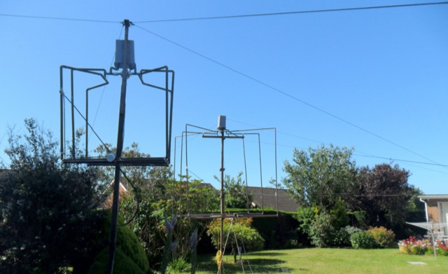 This article describes the development of two tunable antennas each consisting of three interconnected small loops and capable of providing excellent DX performance. The aerials are home-constructed, and located in a very small garden with a minimum of visual impact on the neighbours and are low enough in height to avoid the attention of UK planning authorities.
 -
 Low Band Receiving Antenna, it is a ground independent Receiving antenna which only needs two 10m support poles by DH1TW
 -
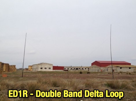
 This project details the construction and testing of a M0PLK Delta Loop antenna for the 20-10m ham radio bands. Inspired by positive reviews highlighting its reduced local QRM compared to Cobweb antennas, the author built the antenna using aluminum tubes, DX-Wire FS2 wire, and a 1:4 balun. A mix of custom 3D-printed parts and careful assembly ensured stability and performance. Initial VSWR measurements met expectations, and test QSOs demonstrated success across multiple bands. Future enhancements include adding a lightweight, remote-controlled rotator for directional capabilities.
 -
 Quads beams consist of 2 1 wavelength (approximately) loops, ordinarily arranged so that one is the driven element and the other is the reflector. In this project author explains how to build a two element Quad Antenna for the 28 MHz.
 -
 Basic magnetic loop antenna examples and loop aerials theory explained. This article inclued some interesting tricks on building magnetic loop antennas and an usefull excell sheet to help compute magneti loop antennas calculating power efficiency from 10 to 40 meters band
 -
 Building A Full-Wave Quad Loop Antenna for 6 Meters. This is an easy antenna to build and the materials cost about $15-20. It exhibits 1.8dB gain over a 1/2-wave dipole. Using an open-wire parallel feedline (commonly called ladder line) with an antenna tuner, it tunes up on the 10m band as a 5/8-wave loop as well
 -
 This 160 meter Delta Loop antenna is made of Hard drawn copper wire AWG 10, the two upper side are 148.5 foot each base wire is 240.9 foot, the feed point at 30.69 foot to one corner, feed with 450 Homs balanced line to an antenna tuner on the ground, then with 50 homs coax to the shack.
 -
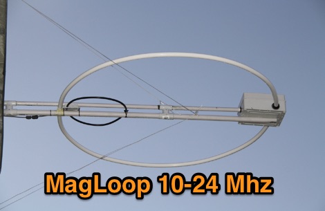
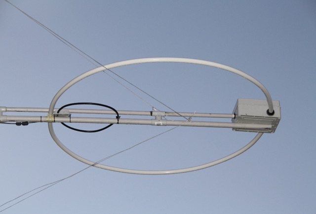 Pictures of a magnetic loop antenna for hf bands that works from 10 MHz to 24 MHz
 -
 A portable loop antenna, made with a 3 meter loop resonates with the chosen capacitor from just below 7MHz to about 28.300MHz which makes it usable on the bands from 40m to 10m.
 -
 The antenna I built was inspired by a portable delta loop designed by Doug DeMaw, W1FB. Given that I constrained myself to a 50-foot roll of speak wire, I scaled my antenna for the 20M band. Using the formula, 1005 divided by the frequency in megahertz, I calculated a total length of 71 feet (21.6 meters) for the center of the 20M band.
 -
 Magnetic loop receive antennas manufacturer. W6LVP loops cover 2200 through 10 meters (135 kHz through 30 MHz) with no tuning or adjustment.
 -
 Original HF magnetic loop antenna designed by the author to work in conjunction with QRP transceivers like the FT-817 in portable operations. In this configuration the loop can operate from 30 to 10 meters. Using a two spires radiator of the same diameter it also covers 40 meters.
 -
 A comprehensive overview of a 10-band attic antenna system developed for contesting and DXing is presented, covering its evolution and performance. Initially intended in a restricted location, the system has been developed through numerous iterations, using various antenna types such as delta loops and Yagis. Automatic switching, dual-direction capability, and optimum tuning for certain band segments are among the most notable features. The project not only improves operating efficiency but also provides great learning opportunities in antenna design and installation in restricted places.
 -
 WB8LZR details the construction and initial field results of a multi-band vertical wire antenna, designed to complement his existing horizontal loop for improved DX on 80 meters. The antenna utilizes a 67-foot vertical wire, configured as a quarter-wave radiator on 80m, and employs a 1:1 current balun for RF isolation on 80m, 30m, and 17m. For bands like 40m, 20m, and 10m, where the wire acts as a half-wave or full-wave radiator, an additional impedance transforming _unun_ is integrated to manage the significantly higher feedpoint impedance and voltage. The author notes the vertical's performance as a receiving antenna, observing reduced noise compared to his main horizontal loop, particularly on 80m, and even hearing some long-path signals the loop missed. Initial QRP contacts, including a **1-watt** QSO with a _VP2 station_ on 30m, demonstrate its transmit capability. While the radial system is currently rudimentary, the project outlines practical considerations for multi-band vertical deployment and impedance matching.
 -
 This study details a reception comparison between vertical and horizontal active loop antennas, specifically two identical _Wellgood active loop antennas_, on various HF bands. The experiment, conducted in a densely populated QRM-prone area, monitored FT8 signals over a 24-hour period using two identical receivers. The methodology involved direct comparison of signal reception across the HF spectrum, aiming to identify performance differences based on antenna orientation. The results indicate that vertical loops demonstrated superior performance on higher bands (10m, 15m, 20m), while horizontal loops excelled on lower bands (30m, 40m, 160m), particularly for receiving long-distance (DX) signals. The horizontal loop's advantage on lower bands is attributed to potentially better low-angle performance and reduced sensitivity to man-made noise, yielding a **2-3 S-unit** improvement on 160m. The study provides practical insights for optimizing antenna placement in challenging urban environments, noting that the horizontal loop consistently showed a **10-15 dB** signal-to-noise ratio improvement on lower bands.
 -
 Discover the best low band receive antennas for hams with limited space. Learn about the K9AY loop antenna and Shared Apex Loop Array, two alternatives to the traditional Beverage antenna. Understand the concept of Relative Directivity Factor (RDF) and compare the performance of different receive antennas. See how the Shared Apex Loop, patented by Mark Bauman (KB7GF), offers an RDF between 8 and 10dB. Find out how to optimize antenna performance and enhance your receive capabilities on 160, 80, and 40 meters. Explore the world of low band receive antennas with insights from WB5NHL Ham Radio.
 -
 This article details a ham radio operator’s experience setting up HF antennas in an antenna-restricted community. Initially using an AEA Isoloop magnetic loop for QRP PSK, the author later built an attic antenna system, including dipoles for multiple HF bands and a slinky dipole for 40 meters. The setup allowed for operation on six bands with acceptable VSWR. Despite space constraints and some compromises, performance was effective. The article highlights practical strategies, emphasizing experimentation and antenna modeling for optimizing performance in limited-space environments. A valuable guide for ham radio operators facing similar restrictions.
 -
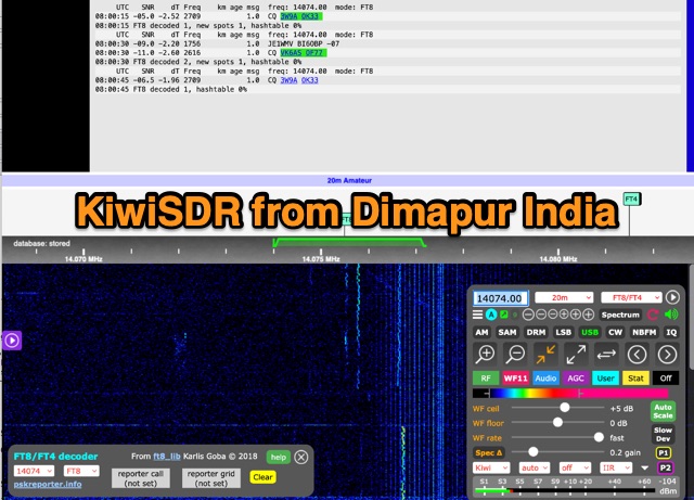 A KiwiWebSDR from Dimapur Nagaland India running a loop antenna for HF bands
 -
 A KiwiWebSDR from Siliguri West Bengal India running a W6LVP loop antenna for HF Bands
 -
 Chavdar Levkov, LZ1AQ, presents an experimental comparison of small wideband magnetic loops, building on his previous work on wideband active small magnetic loop antennas. His research focuses on increasing loop sensitivity by maximizing the short-circuit current, which is directly tied to the "loop factor" M = A/L, where A is the equivalent loop area and L is its inductance. Levkov's methodology involves reducing inductance and increasing area through parallel or coplanar crossed (CC) configurations, comparing these designs against a reference single quad loop of 1 m2 area. Experimental verification included testing three distinct loop types: a simple quad loop, two coplanar crossed (CC) loops, and eight parallel loops, all designed to have a total geometric area of 1 m2. Measurements were conducted at 1.8, 3.5, 7, and 10 MHz using a small transmitter 270 meters away, with a Perseus direct sampling receiver for precise signal level assessment. The results consistently showed that CC loops, particularly Loop 5 (two CC circular loops with 1.44 m2 total area), yielded significantly higher currents, up to 9.1 dB over the reference loop at 3.5 MHz, validating M as a reliable predictor of loop sensitivity. Numerical simulations using MMANA further corroborated the experimental findings, demonstrating an almost perfect correlation between the calculated M factor and the induced loop current for 15 different loop models. Levkov concludes that CC loops offer superior sensitivity for a given loop area, while parallel loops are advantageous for minimizing physical volume. Practical recommendations suggest using loops with an M factor greater than 0.5 uA/pT for quiet rural environments, and he provides a spreadsheet tool, WLoop_calc.xls, to aid in optimizing loop configurations for specific operational needs.
 -
 The F6AOJ RX splitter project was created to split the antenna signal from an LZ1AQ receive loop to multiple receivers, such as radios or SDRs. The design is simple to build and effective. The splitter, mounted on the back of the LZ1AQ control board, provides two outputs—one for an Afedri SDR and another for a K3 transceiver. Measurements show a damping of -3.01 dB at 1 MHz and -3.10 dB at 30 MHz, with a low SWR (max 1.07 at 30 MHz and 1.4 at 60 MHz).
 -
 Integrating a _Software Defined Radio_ (SDR) into an existing ham radio setup involves connecting it with a standard transceiver (TRX), power amplifier (PA), and antennas. The core component is a splitter box that facilitates the connection between the TRX and the SDR, allowing for simultaneous operation without modifying existing equipment. In receive mode, the splitter ties the antenna inputs of both the TRX and a direct conversion receiver (DC RX) together. During transmission, the DC RX input is grounded via a fast telecom relay controlled by the transceiver's -SEND signal, incorporating a 10ms delay for safety. The splitter box includes a 3.7 dB input attenuator for impedance matching and acts as a protective fuse for the DC RX input. Ground loops are mitigated using common mode balun transformers, while the DC RX input is insulated with a broadband transformer. An audio switch box complements the setup, enabling users to listen to either the main transceiver, the SDR output, or both simultaneously. This configuration ensures noise immunity and safety, with the splitter housed in a screened box made from PCB material. On-air tests, such as the CQ WW 160m CW DX Contest, demonstrate the system's effectiveness, showcasing the SDR's ability to handle crowded band conditions with superior selectivity and dynamic range. The SDR's narrow bandwidth filters and waterfall display provide significant advantages, allowing operators to detect weak signals amidst strong interference. The integration of SDR with conventional radios offers enhanced operational flexibility and performance in challenging environments.
 -
 The tri-band trapped delta loop antenna design operates on 80 meters (3.5–4 MHz), 40 meters (7–7.3 MHz), and 30 meters (10.1–10.15 MHz) using a single triangular wire loop. This configuration eliminates the need for an external antenna tuner or band-switching relays. The antenna's physical perimeter, approximately 270 feet, establishes 80M as the fundamental band, with specific trap placements enabling resonance on 40M and 30M. Trap design and placement are critical, with 30M traps positioned inboard of 40M traps within the horizontal element. Each slant leg measures approximately 80 feet. The resource references foundational information from the _ARRL Antenna Handbook_ and _ON4UN’s Low Band DXing_ regarding full-wave loop behavior and feedpoint impedances. The project aims to provide multi-band HF operation from a single, fixed antenna structure.
 -
 This project involved designing a 7-pole Chebychev broadcast band filter to address severe interference issues caused by a new horizontal loop antenna on the KN-Q7A transceiver. The interference overwhelmed the transceiver’s front end, so a custom filter with a 3.5 MHz cutoff was built using silver mica capacitors and type 6 T130 toroidal cores. Encased in a diecast box with SO239 sockets, the filter blocks strong signals from the broadcast band, achieving over 100 dB attenuation. Tested up to 100W, it reduces interference effectively while maintaining low insertion loss across HF bands.
 -
 The ICOM IC-705, a popular QRP transceiver for portable operations, often presents unique challenges for field deployment. This resource details practical solutions for common portable setup issues, particularly for _Parks on the Air_ (POTA) activations. It describes a custom bracket for connecting antennas to the IC-705 through a backpack's antenna flap, utilizing a BNC female-to-female chassis mount connector to mitigate cable tangles. The author shares experiences with a DIY magnetic loop antenna, noting its ease of tuning with the IC-705 and successful CW contacts on 40 and 20 meters over distances exceeding **1000 miles**. Another modification presented is a strain relief solution for the microphone cord, replacing the standard spring clip with an easier-to-attach method. The page also mentions using a _Wolf River Parks antenna_ for POTA activations and references the QRPGuys DS-1 antenna as another portable option. Firmware updates and integration with an LDG Z11-Pro II auto-tuner are also discussed.
 -
 A full-wave delta loop antenna, approximately 141 feet in total wire length for the 40-meter band, offers a low angle of radiation, which is highly advantageous for DX operations. This design, optimized for both 30m and 40m, leverages a specific circumference calculation of 1005/F, ensuring resonance on both bands through a simple switching mechanism. The antenna's configuration enhances long-distance communication, making it a practical choice for hams with limited space. The resource details the construction process, including the use of a _Ceramic Knife Switch_ for band selection and an _RG-11_ matching section to achieve optimal impedance. It outlines the precise loop lengths required for each band, along with tuning secrets to ensure efficient operation. Requiring a minimum height of 12 feet, this antenna can be supported by a single mast or tree limb, making it suitable for suburban installations where stealth or space constraints are a factor.
 -
 Demonstrates the construction of an active loop converter specifically designed for the Low Frequency (LF) bands, addressing common localized noise interference in LF reception. The design integrates a sharply tuned circuit and a tuned loop antenna, utilizing the loop as the sole tuned inductive element. By applying positive feedback, the converter significantly increases the loop's effective Q, achieving factors between 1000 and 2000, which sharpens tuning and reduces noise. The circuit employs an _NE602_ mixer stage, feeding its output to an HF receiver, with a crystal-locked local oscillator at 4 MHz. A 20-turn, 0.8-meter square loop antenna with 500 uH inductance is detailed, connected via 2 meters of figure 8 flex cable. The converter offers three selectable frequency bands: 195-490 kHz, 150-220 kHz (including the New Zealand amateur band), and 128-160 kHz (covering the European amateur band). Performance measurements indicate an effective 3dB bandwidth of approximately 100 to 200 hertz at 200 kHz. The article provides insights into component selection, including an _LF353_ op-amp and a trifilar wound transformer on a ferrite core. Sensitivity figures are presented, showing 7.5 uV of converted output per 1 uV/meter signal strength into a 50-ohm load, or 37.5 uV into an _FRG7_ receiver, highlighting its capability to extract weak signals from noise.