Search results
Query: 6 meter bea on
Links: 169 | Categories: 3
-
 Survey of galactic synchrotron radiation at 408 MHz in the south of England using a 10 metre dish and a Dicke radiometer
 -
 This resource details the construction of a versatile CW/QRSS beacon, designed around a Microchip _PIC16F84_ microcontroller. The project provides a flexible platform for transmitting either standard CW or very slow QRSS signals, making it suitable for LF, VHF, UHF, and SHF applications. It supports two distinct messages, each configurable for speed (from 0 to **127** WPM for CW, or up to **127** seconds per dot for QRSS) and repetition within a six-phase sequence. The core functionality relies on the PIC's EEPROM, which stores all operational parameters, including message content, transmission speeds, phase configurations, and relay control settings. This design allows for parameter modification directly via programming software like _ICProg_ without altering the main program code. The project includes a detailed schematic, a component list, and an explanation of the EEPROM memory mapping for messages, speeds, phase settings, and inter-phase delays. General-purpose outputs (OUT1, OUT2, OUT3) provide dry relay contacts for external control, enabling functions such as power switching, antenna selection, or frequency changes. A 'TRIGGER' input facilitates controlled starts or continuous free-run operation. Sample EEPROM configurations illustrate how to program specific beacon sequences, including message content and relay states.
 -
 A two elements beam antenna tunable from 6 to 20 meters, based on the Maria Maluca antenna project by DB9EX, in german
 -
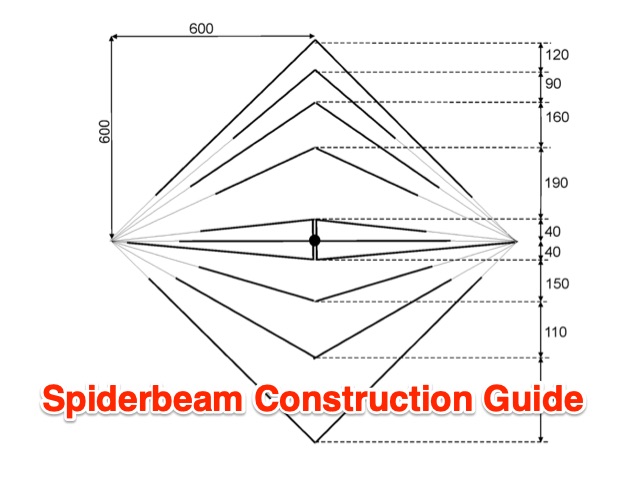 Build a spiderbeam from scratch for 20-17-15-12-10 meters band
 -
 Generating Morse code audio files from text input is the primary function of _MorseGen v1.2_, a utility designed for amateur radio operators. The software allows users to specify the tone frequency and words-per-minute (WPM) speed for the generated CW. A key feature is its ability to create a WAVE audio file containing the Morse code, which can then be used in various applications. The program also supports repeating the generated CW sequence at user-defined intervals, making it particularly useful for creating station identification signals or beacons. The practical application of this tool extends to automated station identification, especially for repeaters or digital mode gateways that require a CW ident. By producing a standard _WAVE file_, the output is compatible with most audio playback systems and software. This functionality provides a straightforward method for integrating custom Morse code messages into existing amateur radio setups, eliminating the need for external hardware keyers for simple identification tasks. The adjustable parameters offer flexibility to match specific operational requirements or personal preferences for CW characteristics.
 -
-
 How to build a beacon keyer for 28 MHz using an old CB Radio transceiver, by Tom Sevart
 -

-
-
 Here is an antenna for the nineties. It's strong, computer designed, and has lots of gain. It is a full size, four element beam on 10, and three elements on 15 meters
 -
 The "Tiny 2" is a great little 2 meter beam. It has some really interesting properties and it is a fantastic first time antenna project for the beginner.
 -
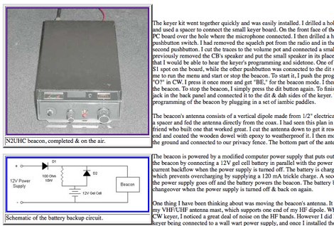
 A vertical antenna specifically designed to work with the 80 meter CW beacon keyer
 -

-
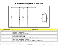 Project plan for a 4 element yagi beam for 50 Mhz
 -
 VA3EXT 5 element beam antenna for 6 meters band
 -
 This magnetic loop is 78cm diameter, with the smaller Hertz loop for tuning. Feeding is by gamma match.
 -
 A project for a homemade multiband Hexbeam antenna for 10, 12, 15, 17 and 20 meters
 -
 Constructing a portable, high-gain antenna for _AO-40_ satellite operations presents unique challenges, particularly regarding mechanical stability and parabolic accuracy. This resource details the build of a 1.2-meter "brolly dish" antenna, utilizing a non-conducting fiberglass umbrella frame as its foundation. The project outlines a method for achieving a parabolic shape using stressed aluminum fly screen mesh, guided by practical geometry and a temporary dowel template. Key steps include selecting an appropriate umbrella with a suitable f/D ratio (ideally >0.25), removing the original fabric, and precisely cutting and attaching eight segments of fly screen to the struts to form the reflective surface. The construction process, which took approximately five hours for the author, _G6LVB_, resulted in a dish with an f/D of 0.27 (depth=270mm, diameter=1160mm, f=310mm). The article also describes a modification to a _TransSystem AIDC_ feed, incorporating a PCB reflector behind the dipole for easier mounting. Performance tests at a squint angle of 15 deg and a range of 50,000km yielded a signal-to-noise ratio of 33dB on the S2 beacon and 23dB for SSB signals, indicating strong reception. The author notes that the modified umbrella may not close fully without risking surface disfigurement.
 -
 An Attic version for limited space applications by NW9T
 -
 The Vee Beam antenna project presents a versatile solution for hams, enabling operation across all eight High Frequency bands (80m to 10m) with significant gain on 20m to 10m. This easy-to-construct antenna utilizes two long wires at an angle, enhancing directional performance and minimizing ground losses. With a low visual profile, it is discreet and effective for various applications. The design allows for optimal leg lengths and included angles, ensuring robust performance while maintaining simplicity in construction and operation. The V Beam antenna is an aerial that you can use on all eight High Frequency amateur bands (80, 40, 30, 20, 17, 15, 12 and 10m) with an antenna tuner, and which gives significant gain on the five bands from 20 to 10 meters band.
 -
 The 9A3MR contest QTH rental provides a fully equipped amateur radio station for DXpeditions or radio holidays on Murter Island, Croatia. The station features a Drake TR7 transceiver and a 16-meter tower with a rotator, suitable for various HF operations. Accommodations include a four-room apartment and a studio apartment, both within 200 meters of the beach, offering amenities like parking and a barbeque area. This QTH is located in Jezera, a fishing village with local stores and restaurants within a five-minute walk. While Murter Island itself does not qualify for IOTA due to a bridge connection, the Kornati Islands National Park (IOTA EU-170) is only 10 nautical miles away, with daily tourist tours available. The Krka National Park is also accessible by car, approximately 25 km distant, providing additional recreational opportunities.
 -
 2,6 and 10 meters beacon located at Lake White, Ohio
 -
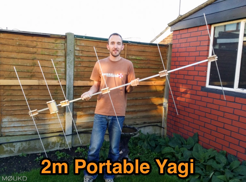 Building a 2 metre 144MHz VHF Yagi beam antenna, designed for portable use.
 -
-
 A 21 MHz Four Square Beam Antenna This popular antenna for the lower bands, can also work well on 15 meters, QST Article
 -
 VectorFox is a software born to incorporate a PC into the fox hunting environment. VectorFox is able to take inputs from up to 5 sources, such as a 2m beam, a 2m signal meter, a TDOA, etc, and display the results on the screen. VectorFox also accepts Agrelo inputs. From these results the operator can choose which indication is best and have a line drawn on the map in the direction of the signal.
 -
 Cushcraft X7 20-15-10 Meter 7 element beam Assembly & Installation
 -
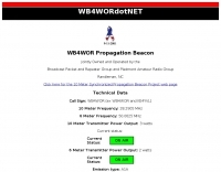 WB4WOR Propagation Beacon on 6 and 10 meters Jointly Owned and Operated by the Broadcast Packet and Repeater Group and Piedmont Amateur Radio GroupRandleman, NC USA
 -

-

-
 Exagonal Beam antenna cover 20-17-15-10 meters By KE4NU
 -
 This project details the construction of a **full-sized 40-meter vertical antenna**, born from a renewed interest in 7 MHz operation and a desire for improved effectiveness over simple dipoles. The author, K5DKZ, initially focused on VHF experimentation, which provided an inventory of aluminum tubing and fiberglass spreaders for this endeavor. Before this vertical, K5DKZ utilized an 80/40 meter inverted-vee trap dipole and a 40-meter broadband dipole, but now primarily uses a pair of full-sized, phased, quarter-wave verticals spaced 35 feet apart for serious 40-meter work. The construction involves a base-heavy design for stability, using a 44.5-inch section of 1-1/4 inch steel TV mast driven into 1-3/8 inch aluminum tubing, insulated by a 105-inch section of Schedule 40 PVC pipe. The assembly reaches 31 feet, close to the 32 feet required for a quarter-wavelength on 40 meters, with fine-tuning achieved by winding wire onto a fiberglass spreader. The design is explicitly presented as a foundation for a two-element 40-meter Yagi beam, outlining modifications like substituting aluminum for steel in the base and using an inductive hairpin match for the driven element. The article also discusses tuning considerations for a large 40-meter beam, noting the 100 to 200 kHz upward frequency shift when raised, and suggesting methods for installation on a tower. The author emphasizes the cost-effectiveness and good performance of the monopole approach, especially when multiple verticals are needed.
 -
 A fractional bandwidth of up to 30:1 characterizes spiral antennas, making them highly effective across a very wide frequency range, often from 1 GHz to 30 GHz. The resource details two primary types: the **Log-Periodic Spiral Antenna** and the **Archimedean Spiral Antenna**, defining each with specific polar functions and illustrating their planar configurations. It explains that spiral antennas are typically circularly polarized, with a Half-Power Beamwidth (HPBW) of approximately 70-90 degrees, and a peak radiation direction perpendicular to the spiral plane. The content elaborates on critical design parameters affecting radiation, including the total length (outer radius) for lowest frequency, the flare rate ('a' constant) for optimal radiation versus capacitive behavior, the feed structure (often an infinite balun) for high-frequency operation, and the number of turns (typically 1.5 to 3 turns). It also discusses the theoretical impedance of 188 Ohms for Log-Periodic spirals, derived from Babinet's Principle, noting actual impedances are often 100-150 Ohms. The article presents a simple construction method for an Archimedean spiral, demonstrating VSWR and efficiency measurements. Measurements from a constructed spiral antenna show a VSWR that is fairly constant across the band, albeit with a mismatch loss of about 3 dB. The antenna efficiency remains around -5 dB (31.6%) across its operating range, indicating a decent wideband radiator despite opportunities for optimization.
 -
 The Gizmotchy high performance horizontal and vertical beam antenna for 2/6/10/11 meter bands
 -
 Info and specifications on my three beacons on 10 and 6 meter bands. You will find also informations on the propagation for these two band.
 -
 Design and build an 6 m dipole antenna from aluminum, tubing, that resembles the active element of a yagi beam antenna.
 -
 An homebrew project for a 3 element coil-loaded Yagi beam antenna for 40 Meter band
 -
 Article describing how to homebrew a yagi antenna for 50 MHz, includes plans for a four and five elements yagi beam and details how how match impedence with a gamma match
 -
 10 meter propigation beacon project
 -
 In this PDF article Zack Lau describe how to homebrew a four element yagi beam antenna for 50 MHz band, including how to build mounting blocks and tubing clamps to hold elements.
 -
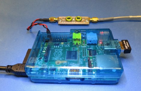 Settng up a 40 meter WSPR beacon based on Raspberry Pi by VA3PAW
 -
 A project that describes a build a multiband wire beam antenna. A 3 band single feed moxon antenna for 20,15,10 meters.
 -
 Demonstrates the operational status and reception reports for the SK6RUD/SA6RR QRPP beacons, which transmit on 478.9 kHz, 1995 kHz, 10.131 MHz, and 40.673 MHz. These beacons utilize extremely low power, with the 630-meter beacon operating at approximately 0.1 watt ERP into an L-antenna, showcasing the potential for long-distance contacts under favorable propagation conditions. The site details the specific frequencies and antenna types employed, such as a vertical at 500 kHz and a 1/4 vertical for higher bands. The resource compiles over 10,530 reception reports from amateur radio operators worldwide, logging details such as date, time, band, RST signal report, locator, distance, and receiver setup. Notable long-distance reports include a 500 kHz reception by AA1A-Dave from 5832 km in 2008 and a 10.133 MHz reception by ZL2FT-Jason from 17680 km in 2010, illustrating the global reach of these low-power transmissions. Each log entry provides specific equipment used by the reporting station, including transceivers like the Yaesu FT817, ICOM IC-7300, and various antenna configurations such as coaxial mag loops, inverted Ls, and end-fed wires. The primary objective of the SK6RUD beacons is to challenge conventional notions of power requirements for effective two-way communication, proving that contacts over significant distances are achievable with minimal output. The site also includes a submission form for new reception reports, fostering community engagement and continuous data collection on propagation phenomena across different bands. The detailed logs offer practical insights into real-world propagation characteristics and the efficacy of QRPP operations.
 -
 A 5 element yagi beam antenna for ten meters band with full dimentsions, eznec file and coax match informations for 50 ohms feed line
 -
 The article details a specific method for performing maintenance on a crank-up tower, focusing on cable and rotator replacement without a full power pulldown. It outlines the necessary equipment, including a 2-section extension ladder with a horn attachment and a two-piece, 6-foot steel pipe, specifying a 1 1/4-inch diameter. The procedure involves lowering tower sections onto the internal pipe to slacken cables, allowing for their removal and replacement, and also describes how to replace the rotator while the tower remains upright. Key steps involve using the pipe to support tower sections, enabling access to the cables and bearings. The author, N5AR, emphasizes safety by instructing the reader to remain on the ladder at all times, rather than climbing the tower itself. The process is presented as manageable for a single operator, with the author having successfully completed the task on a _UST TX472_ tower. Specific tools mentioned include Allen wrenches and end wrenches for cable ends and bearing bolts. The method provides a practical approach for tower upkeep, minimizing the complexity often associated with such tasks and allowing for maintenance of components like cable pulleys and their bearings.
 -
-
 50MHz Collapsible 2 Element Mini Beam antenna, an overview the development of the 6MBA.
 -
 This resource provides a unique historical audio archive of 50 MHz DX contacts, documenting significant F2 and Es propagation events experienced by PA2S (formerly PA2HJS) since 1978. The collection includes recordings of beacons and two-way QSOs with stations across North America, South America, Asia, Australia, Europe, and Africa. Specific entries detail contacts with rare DX entities such as ZS6PW, VE1AVX, C5AEH, J52US, TR8CA, LU8MBL, VK8ZLX, and various Japanese stations, often noting the mode (SSB or CW) and propagation type. The archive also highlights challenging pile-up situations and frustrating near-misses during major openings. The recordings, initially in RealAudio format for solar cycles 21 and 22 and later in MP3 for cycle 23, offer a practical illustration of 6-meter band conditions over several solar cycles. The content allows hams to listen to actual signals from different continents, observing signal characteristics like typical TEP fading from 5H3RA or strong F2 backscatter from OZ1BVW. It provides a comparative perspective on propagation effectiveness between solar cycles, noting that cycle 23, while not as robust as previous cycles, still yielded interesting openings. The archive serves as a valuable educational tool for understanding real-world 50 MHz DXing and propagation phenomena.
 -
 A 4 element yagi beam antenna for the 17 meters band with pictures and element dimension and spacing
 -
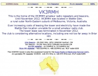 Running 10 and 6 meters beacons, 6 m and 70 cm fm repeater from Melbourne, Australia