Search results
Query: adjust
Links: 219 | Categories: 1
-
 The document provides a detailed guide on modifying an inverted-L antenna to include the 160 meters band. This enhancement allows amateur radio operators to utilize the lower frequency effectively, which is crucial for long-distance communication, especially during the night. The inverted-L design is popular due to its compact size and ease of installation, making it suitable for various environments. By adding top band capabilities, operators can engage in DXing and contesting on 160m, expanding their operational range and opportunities. The guide includes practical tips and considerations for construction, ensuring that the antenna maintains its performance across the extended frequency range. It discusses the necessary adjustments and materials required for the modification, along with potential challenges and solutions. Whether you are a seasoned operator or a beginner, this project can enhance your station's capabilities, allowing for more versatile operations and improved signal quality on the 160m band.
 -
 These instructions use simple, generally familiar examples of equipment types and are designed to help you find the adjustment that suits you best. If you are looking on how to adjust a morse key, bencher key, paddle or straight morse key, here you will find all instructions.
 -
 Demonstrates the design principles and performance characteristics of **corner reflector antennas**, emphasizing their high gain and directional properties. It covers critical design factors such as the corner angle and the spacing between the radiating dipole and the reflector vertex. The resource explains how reducing the corner angle increases gain but lowers feed impedance, making matching more challenging. Practical angles of 90 degrees or 60 degrees are discussed, with 90 degrees offering easier impedance matching despite slightly lower gain. Details key design considerations, including reflector side length exceeding two wavelengths and reflector width greater than one wavelength for a half-wave radiator. It specifies reflector construction using wire netting, sheet metal, or parallel metal spines spaced less than 0.1 wavelength. The article provides a table with general dimensions for UHF and VHF bands, noting typical impedance values of 50 to 75 ohms and expected SWR of 1.7:1 on the lower band edge. Adjustable radiator-to-vertex spacing is highlighted as crucial for final tuning.
 -
 This 4m Slim Jim Antenna is cheap and easy to build yet it greatly out performs the more usual dipole due to its low angle of radiation. An SWR of 1:1 is obtainable across the 4m ham radio FM band with a simple adjustment.
 -
 N1HFX article on adjustable voltage regulator
 -
 This document details the design and construction of a Vinecom 6N4 dual-band Yagi antenna for the 50MHz (6-meter) and 70MHz (4-meter) amateur radio bands. The antenna features 9 total elements (4 elements for 50MHz, 5 elements for 70MHz) on a 4.236-meter aluminum boom. Computer simulations using MMANA software predict 7.21 dBd gain on both bands with front-to-back ratios of 16.01dB (6m) and 15.37dB (4m). The design uses 12.7mm diameter elements mounted on a 32mm square boom, weighing 5.7kg total. Practical measurements with an MFJ-269 analyzer confirmed good SWR performance across both bands after element length adjustments.
 -
 Adjusting audio output of your soundcard to obtain a perfect PSK signal from your transmission. A project to help you tuning your PSK31 emission.
 -
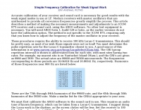
 Accurately determining an antenna's feedpoint impedance is crucial for optimal performance, especially when experimenting with new designs or making adjustments. While SWR meters provide basic information, a full complex impedance measurement reveals the resistive and reactive components, which are essential for proper matching. Modern antenna analyzers, like the _Palstar ZM30_ or MFJ259B, simplify this task, but measurements taken through a transmission line require careful interpretation due to impedance transformation. This resource details a calibration method to precisely account for the effects of the feedline. It explains how a transmission line can significantly alter the measured impedance, illustrating this phenomenon with a Smith Chart example where an 80m antenna's [22 + j6] Ohms feedpoint impedance transforms to [82 + j45] Ohms after a 10m line. The guide demonstrates using a transmission line calculator applet, such as the one by W9CF, to reverse this transformation. It outlines the process of calibrating a specific length of RG174 coax, showing how an initial 26ft estimate was refined to **25.85ft** to accurately predict a known 22 Ohm load, significantly improving accuracy over uncalibrated results.
 -
-
 Controlling amateur radio transceivers remotely often requires dedicated software to interface with the radio's CAT (Computer Aided Transceiver) system. CATSPAW is a software utility specifically developed by N2OHZ for the Yaesu FT-100, facilitating computer-based control over various radio functions. The software provides an interface for adjusting parameters such as frequency, mode, and other operational settings, which can be particularly useful for remote station operation or automated tasks. While the specific features and user interface details are not extensively documented on the download page, the primary function centers on providing a digital control layer for the _FT-100_. This allows operators to integrate the transceiver into a larger station setup that might include logging programs or digital mode applications, enhancing the overall operational flexibility. The utility's design focuses on direct control, leveraging the radio's internal command set. As a downloadable executable, _CATSPAW_ represents a common approach to radio control software from its era, offering a direct link between a personal computer and a specific transceiver model.
 -
 An home made vertical dipole antenna made with simple material. The antenna has a total length of aproximately 16 feet. In this article appeared on June QST 2019, the author explain how he reached the optimal confirugation changing and adjusting the lower part of the antenna, trimming and spacing correctly the copper wire. PDF File to downloas
 -
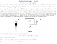
 A 4 AMP / 18V regulated power supply schematic, designed by _ON6MU_, provides a detailed circuit diagram for constructing a robust power source. The design focuses on delivering a stable 18-volt output at up to 4 amperes, crucial for powering various amateur radio equipment. This resource presents a clear visual representation of component interconnections, including rectifiers, filter capacitors, and voltage regulation stages, essential for DIY enthusiasts building their shack infrastructure. The schematic's clarity facilitates understanding the power flow and component roles within the circuit. This circuit design offers a practical solution for hams needing a reliable 18V supply, potentially useful for driving specific transceivers, amplifiers, or accessory circuits. While specific performance measurements or comparisons to other designs are not detailed, the schematic itself serves as a foundational blueprint. Builders can adapt or modify the _power supply_ to suit their particular needs, such as integrating overcurrent protection or fine-tuning the output voltage with adjustable regulators. The straightforward presentation makes it accessible for those with basic electronics knowledge to assemble and troubleshoot.
 -
 Presents a QRP AM/CW transmitter project specifically designed for the 10-meter band, utilizing a crystal oscillator and a collector-modulated AM oscillator. The design employs a 2N2219(A) transistor in a Colpitts configuration, generating 100 to 350 mW of RF output power depending on the 9-18 Volt supply voltage and modulation depth. Frequency stability is maintained by a 28 MHz crystal, with fine-tuning possible via a Ct1 trimmer capacitor for approximately 1 kHz adjustment. The resource details the RF oscillator stage, implemented with a 2N2219 NPN transistor, emphasizing frequency stability and low power dissipation. It also covers the amplitude modulation stage, managed by a 2N2905 PNP transistor, which impresses audio information onto the carrier. Selective components (C3, C4, C7, C5) enhance voice frequencies within a +/- 5 kHz bandwidth, and modulation depth is controlled by R2 and R3. The project includes a 3-element L-type narrow bandpass filter (Ct3, L3, C10) to suppress harmonics and ensure a clean output signal. The project provides a complete schematic diagram, a comprehensive parts list including specific capacitor, resistor, and inductor values, and construction notes for the coils (L1, L2, L3). It also offers practical advice on enclosure requirements, suggesting an all-metal case or a PVC box with graphite paint for RF shielding. Operational parameters such as current draw (27mA@9V to 45mA@16V) and input impedance (50 Ohms) are specified, alongside guidance on antenna matching and the importance of a valid amateur radio license for 10-meter band operation.
 -
 This handy and cheap portable dipole can be folded and backpacked, carried in use, and adjusted to a very wide range of frequencies by KV5R
 -
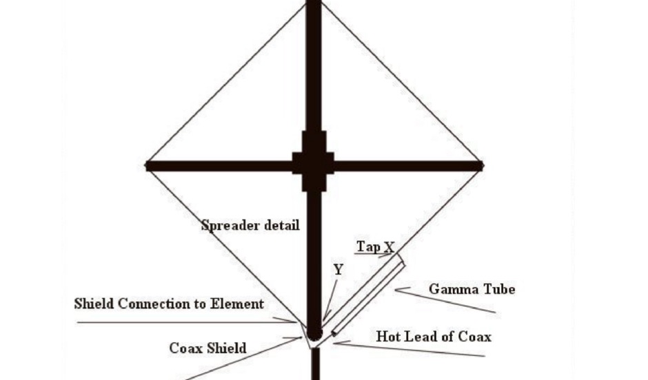 A two meter Quad antenna project with detailed instructions on how to adjust the Quad gamma match
 -
 The Elecraft K2 transceiver requires specific modifications for optimal soundcard digital mode operation, particularly for PSK31. The original article, circa 2001, details initial challenges with manual PTT and speech compression settings. A key modification involves adding headphone audio and a compression disable signal to the K2's microphone jack, utilizing pins 4 and 5. The **COMP0** signal, active low, is shorted to ground via a non-inverting open collector switch circuit, comprising two resistors and two transistors, mounted on the SSB board near U3. This circuit provides effective control of an analog signal line with good noise immunity. The switchbox itself repurposes a computer COM port switch, using only two of its original connectors and four of the nine poles. It integrates a microphone preamplifier, a PTT circuit built with 'flying leads' construction, and RCA jacks for soundcard connections. A trimpot adjusts the audio drive to the K2. The central DB9 connector links to the K2's mic connector via a shielded RS232 serial cable, ensuring proper grounding and signal routing. An external footswitch PTT jack is also included. Further enhancements include a **noise-canceling microphone** preamp based on a QST December 2000 article, adapted for Heil mic elements. This preamp, built with pseudo-Manhattan style construction, provides a gain of approximately 2 by changing emitter resistors (R9 and R16) from 680 ohms to 330 ohms. A 10-ohm series resistor and 47 µF capacitor on the +5V supply mitigate noise spikes.
 -
 Demonstrates the adaptation and construction of a 7-element DK7ZB Yagi antenna for the 4-meter band (70 MHz), utilizing components from a defunct 2-meter CUE DEE Yagi. The resource details the modifications made to the original DK7ZB design to fit the shorter CUE DEE boom length, specifically adjusting element lengths for 6mm rod elements while reusing existing mounting holes for the reflector and last director. It provides precise element lengths for the reflector, dipole (12mm aluminum tube), and five directors, along with a note on cutting elements for transport. The article includes a 4NEC2 simulation file for performance analysis and an SWR plot, confirming the antenna's electrical characteristics. It also specifies the calculation for the quarter-wavelength matching cable using SAT752F coaxial cable, resulting in a 909mm length. Practical application is shown with the finished antenna in operation at JO20XC, listing several activated Maidenhead squares such as JO56PA and JP40KS, validating its effectiveness for portable 70 MHz operations.
 -
 Demonstrates the construction of a custom programming cable for Yaesu VX-7R and VX-5R handheld transceivers, enabling computer interfacing for memory management and frequency coverage adjustments. The resource details a six-transistor circuit design, powered by the computer's RS232 interface, utilizing readily available and inexpensive discrete components. It includes a complete bill of materials, specifying transistors like the _2N2222_ and _2N3906_, diodes, and resistors, along with a matrix board layout for compact assembly within a 75x50x25mm enclosure. The guide provides practical tips for working with matrix board, such as scoring and snapping, track cleaning, and component soldering order. It outlines the specific connection requirements for both the VX-7R (via Yaesu's CT-91 breakout lead with a 2.5mm stereo jack) and the VX-5R (via CT-44 or a four-section jack), detailing signal and ground pinouts. The author successfully tested three circuits, documenting the one with complete two-way communication, allowing users to program their rigs with software like _VX-7 Commander_ and achieve capabilities beyond commercial cables, including band adjustments.
 -
 The 10-minute, 25-second video demonstrates making a QSO via the VO-52 amateur radio satellite, focusing on real-time Doppler shift correction. It features Simon, 2E0HTS, operating a Yaesu FT-847 transceiver and a homebrew dual-band Yagi antenna, specifically a 10-element 435 MHz Yagi for uplink and an IO Loop for 145 MHz downlink. The video visually details the operator's technique for continuously adjusting the uplink frequency to compensate for the satellite's changing velocity relative to the ground station, a critical aspect of successful satellite communication. The demonstration highlights the practical application of Doppler compensation, showing the operator tuning the transmit frequency to maintain a stable received signal from the satellite. This approach contrasts with systems employing automatic Doppler correction or full-duplex operation, providing insight into manual frequency management for satellite passes. The video serves as a direct, observational guide for hams interested in LEO satellite operations, particularly those using non-tracking, manually tuned setups.
 -
 The ZS6BKW multi-band antenna, an optimized variant of the classic G5RV, is presented with detailed construction and tuning instructions. This resource outlines the antenna's design principles, which were developed by _Brian Austin (G0GSF)_ using computer programs and Smith charts to achieve optimal dimensions. It provides specific guidance on calculating and adjusting the lengths of the radiators (L1) and the matching ladder line (L2), emphasizing the critical role of velocity factor (VF) in achieving resonance. The article includes a step-by-step procedure for empirically determining the VF of ladder line using an antenna analyzer, ensuring accurate physical lengths for the matching section. It details the tuning process for the radiators, offering practical tips for incremental adjustments to achieve the best SWR curve. The resource presents SWR measurement results obtained with an _AIM-4170C_ analyzer across multiple bands, alongside predicted SWR graphs from an AutoEZ model. It confirms successful contacts on 80, 40, 20, and 17 meters, including a **17-meter DX contact** to Italy. EZNEC and AutoEZ models for the ZS6BKW antenna, covering 80 through 6 meters, are provided for download, allowing further analysis and customization. The document specifies component details, such as the use of Wireman 554 ladder line and #14 AWG THHN copper wire, and discusses the antenna's performance characteristics, noting high SWR on 15 and 30 meters but successful tuning on 6 and 80 meters with an external tuner.
 -
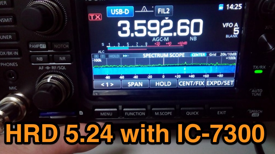 The Icom IC-7300 is a popular HF transceiver among amateur radio operators, known for its advanced features and ease of use. However, integrating it with software like Ham Radio Deluxe (HRD) can be challenging due to compatibility issues. This guide provides step-by-step instructions on how to configure the IC-7300 to work seamlessly with HRD 5.24, the last freeware version available. It covers the installation of necessary drivers, setting up virtual COM ports, and configuring audio settings for digital modes. To begin, users must download and install the Icom USB driver, which creates a virtual serial COM port for communication between the radio and the computer. The guide details how to check for this new port and adjust the CI-V address settings to ensure proper communication. It also explains how to set up the soundcard settings in HRD for digital modes, allowing operators to transmit and receive audio effectively. Following these instructions will enable IC-7300 owners to maximize their radio's capabilities with HRD.
 -
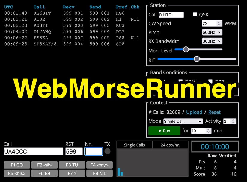 Web Morse Runne is an online CW (Morse code) contest simulator developed by DJ1TF - Thomas Fritzsche. This tool allows users to practice their Morse code receiving and sending skills in a simulated contest environment. Key configurable parameters include CW speed, with options ranging from 300Hz to 900Hz, and RX bandwidth, adjustable from 100Hz to 600Hz. Users can also set a monitor level and simulate various band conditions. The interface includes counters for calls and QSOs per hour, along with a timer. Pre-defined function keys are available for common contest exchanges such as F1 (CQ), F3 (TU), F6 (B4), F7 (?), and F8 (NIL). The simulator is designed for ham radio operators looking to improve their CW contesting proficiency.
 -
 A system designed to automatically tune small transmitting magnetic loop antennas, particularly beneficial for **contest operations** where rapid frequency changes are common. The core of the system involves a PC-based control application, AutoCap, written in C#, which monitors antenna SWR via an external meter and commands a motor interface to adjust the loop's variable capacitor. The software is compatible with Windows and Linux via the Mono framework, offering a graphical user interface for monitoring system status, SWR, power, and motor commands. Key components include one or more magnetic loop antennas equipped with DC or stepper motors for capacitor adjustment, an SWR meter with data output (such as the Telepost LP-100A or a homebrew serial/USB SWR meter), the AutoCap PC software, and a motor interface. The most effective motor interface utilizes an **Arduino-based controller** with custom firmware, providing precise control over both simple DC motors and stepper motors, and supporting features like motor braking for finer adjustments. The system allows for configurable SWR thresholds, pulse widths, and motor effort settings to optimize tuning speed and resolution. Optional radio integration provides frequency hints, enabling the algorithm to learn the relationship between motor actions and resonant frequency, thereby speeding up initial tuning responses. The software also supports antenna profiles, allowing operators to save and recall specific configurations for different loops, including accumulated frequency hint data.
 -
 Digital Smart antenna (DiSA) Automatically Adjusts over a wide band of frequencies.
 -
 Designing and constructing portable wire antennas for HF operations, this resource explores several configurations including the _foldback dipole_ for space-constrained setups and an inductively shortened dual-band dipole for 20m and 40m. It details the calculation of inductance for shortened elements, providing a Visual Basic 6.0 program screenshot that illustrates determining coil parameters like turns and length for a **25.5 uH** inductor. The document emphasizes practical considerations such as adjusting wire lengths for optimal SWR, noting that a dual-band dipole achieved SWR below 2:1 on both 20m and 40m, with careful adjustment bringing it under 1.5:1. Further, the resource describes a half-wave antenna matched with a coaxial stub, a method often referred to as the _Fuchskreis_ in German amateur radio circles, to transform the high feedpoint impedance to 50 Ohms. This monoband solution, for a 20m application, uses a stub length of **2.98m** (0.216 lambda multiplied by coax velocity factor) and a shorted stub of approximately 48cm. The coaxial stub design is highlighted for its resilience to ground proximity, allowing it to be rolled up or laid on the ground with minimal SWR impact, making it highly suitable for portable QRP operations.
 -
 Find out how much to adjust the length of a quarter wave whip or a half wave dipole rather than the outright cut-and-try method.
 -
 Accurate calibration of your receiver and sound card is necessary for good results with the weak signal modes in use at LF. Modern receivers with master oscillators that are synthesized to provide all conversion frequencies greatly simplify the process. This article describes a method of making the necessary measurements and adjustments to an ICOM R75 receiver and a sound card, using the ARGO software
 -
 The resource details the construction of a multiband trap-style Inverted-V antenna designed for operation on 3.5 MHz, 7 MHz, 14 MHz, 21 MHz, and 28 MHz. It presents specific winding data for the traps, including the number of turns, wire gauge, and coil former dimensions, crucial for achieving resonance on the target bands. The document provides a parts list and a diagram illustrating the antenna's physical layout and trap placement. It outlines the process for building the traps using PVC pipe formers and specifies the required capacitor values for each trap. The design emphasizes a practical approach to achieving multiband operation with a single feedline, a common goal for HF operators with limited space. The document includes a table with antenna segment lengths for each band, allowing for precise replication of the design. It also offers insights into tuning and adjustment, ensuring the antenna performs optimally across the designated amateur radio bands.
 -
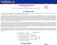 The use of dummy load is mandatory for off-air adjustment of the transmitters. Build one.
 -
 The **136kHz Vertical Antenna** at G3YMC employs a Butternut HF2V structure, standing 10m tall. It integrates a 6.5mH loading coil to achieve resonance, with a matching transformer for impedance adjustment. The antenna's configuration includes top loading via a 12m horizontal wire, enhancing capacitive impedance. Initial measurements indicated a high impedance of around 300 ohms, necessitating a transformer for a 50-ohm match. Despite challenges with ground losses, the vertical antenna has shown improved performance in specific directions, filling nulls present in the previous loop antenna setup. The tuning remains broad, with variations due to environmental factors affecting the matching. Ongoing adjustments and comparisons with the loop antenna will continue to refine its effectiveness.
 -
 The NB6Zep Antenna, an electrically shortened 80-meter end-fed wire, addresses space constraints for low-band operation by integrating two loading coils into a 37-foot wire. This design, modeled with _EZNEC_, explores configurations like the quarter-wave sloper and inverted-L, with the latter providing a more vertical radiation pattern and practical backyard deployment. The resource details specific coil construction, recommending 21 uH coils made from _BW coil stock #3026_ or similar, and outlines wire segment lengths for optimal tuning. Performance analysis indicates a radiating efficiency of approximately 27% with good ground conductivity, resulting in a signal typically 3-4 dB down compared to a full-size quarter-wave vertical. The antenna exhibits a narrow bandwidth, around 50 kHz, due to its high Q, necessitating a tuner for broader band operation. Feedpoint impedance is low, with ground resistance playing a critical role in achieving a usable SWR. The article emphasizes the importance of an effective ground rod at the feedpoint for proper operation and tuning, suggesting an antenna analyzer for precise adjustments. It confirms the antenna's suitability for DX, citing successful contacts from Oregon to the East Coast and Hawaii on a 160-meter variant, making it a viable option for urban operators seeking low-angle radiation on 80 meters.
 -
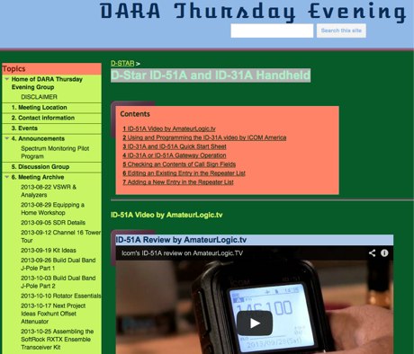 Manually programming D-Star handheld transceivers like the _Icom ID-51A_ and _ID-31A_ can be a straightforward process, enabling operators to configure repeaters, simplex frequencies, and D-Star specific settings without relying on computer software. This method is particularly useful for field operations or when quick adjustments are needed, allowing hams to set up callsign routing, DR mode, and reflector links directly from the radio's interface. Understanding the menu structure and key sequences is crucial for efficient on-the-fly programming. Operators often find manual programming invaluable for activating new D-Star repeaters encountered during travel or for participating in local nets where specific G2 or G3 gateway configurations are required. While software like _CS-51_ offers convenience for bulk programming, the ability to manually input frequencies and D-Star parameters ensures operational flexibility. This approach also helps hams troubleshoot connectivity issues by verifying individual settings directly on the transceiver, ensuring proper D-Star registration and gateway access.
 -
 This sweeper built for a narrow bandwidth filter adjustment, use a simple 555 version sawtooth wave generator.
 -
 Demonstrating the construction of a short dipole antenna tailored for the 60 meter band, this resource provides detailed instructions for radio enthusiasts with limited space. The design incorporates inductive loading using two inductors (L1/L2) made from PVC tubes, allowing for effective operation on 5 MHz. The antenna consists of 12 meters of wire, divided into four sections, with specific dimensions and materials outlined for optimal performance. Results from users indicate that this antenna can significantly enhance DXing capabilities on the 60 meter band. Feedback from operators suggests that while the design is effective, adjustments may be necessary based on individual setups, such as coil diameter and wire gauge. Many users report successful construction and operation, with some experimenting with variations to improve resonance. The practical application of this antenna design has led to successful contacts and improved signal quality, making it a popular choice among 60 meter band operators.
 -
 The **Solarcon A99** vertical antenna, a half-wave over a quarter-wave variable mutual inductance design, primarily serves the 11-meter CB band but also finds use on 10 and 12 meters for amateur radio operators. Its simple construction, consisting of three fiberglass sections and a 16 AWG radiating element, makes it an accessible option for new operators or those seeking an easy-to-install base station antenna without complex mounting requirements. Despite claims of 9.9 dBi gain being widely considered exaggerated, and a manufacturer rating of 2000 watts power handling often viewed with skepticism (with 300 watts suggested as a practical limit), the A99 maintains popularity due to its low cost and ease of deployment. It typically tunes to a 1.2-1.3 SWR out of the box, requiring minimal adjustment via its two tuning rings. Its high angle of radiation allows for effective local communication even when mounted at low heights, such as 8-10 feet off the ground. However, the A99 is known for significant RF bleed-over issues, particularly when operated with higher power or mounted close to residential electronics. While its internal design is often described as cheap, the antenna exhibits remarkable durability, frequently lasting a decade or more in various weather conditions. Its affordability and straightforward setup continue to make it a go-to choice for many radio enthusiasts.
 -
 Improper tank adjustment and excessive drive are equally harmful to component life, and either can create splatter
 -
 The Icom AH-4 autotuner operates efficiently across multiple HF bands, providing seamless automatic tuning for antennas from 3.5 MHz to 54 MHz. Its robust design allows for outdoor installation, making it suitable for field operations and fixed stations. The unit interfaces with Icom transceivers via a control cable, enabling automatic band switching and tuning. The AH-4 is capable of handling up to 120 watts of RF power, ensuring compatibility with most amateur radio setups. Its weather-resistant casing and compact form factor make it a versatile choice for operators requiring reliable performance in diverse environments. Field tests demonstrate the AH-4's ability to maintain low SWR across its operational range, enhancing signal quality and transmission efficiency. Compared to manual tuners, the AH-4 offers significant time savings and ease of use, particularly in rapidly changing band conditions. Its integration with Icom radios simplifies operation, eliminating the need for manual adjustments. The autotuner's performance is consistent with other high-end models, providing a cost-effective solution for amateur operators seeking dependable tuning capabilities without sacrificing performance.
 -
 Constructing a high-power 70cm solid-state amplifier presents unique challenges, particularly when aiming for 500 watts output using modern LDMOS devices. This resource details the author's experience building a 70cm amplifier based on a _Freescale MRFE6VP5600H_ transistor, initially from an RFHAM kit. It meticulously outlines the necessary modifications to achieve advertised performance, including optimizing input and output matching, correcting bias circuitry, and ensuring proper output balun connections for stability. The author shares specific adjustments, such as trimming the prototyping board for better transistor fit, drilling additional mounting holes for improved heat sinking, and replacing original matching capacitors with a single _20pf MIN02 metal mica_ for superior output. A critical fix involved jumpering gate decoupling pads to balance the push-pull transistor halves, which increased output to 580W and improved IMD. The resource also highlights a crucial correction to the output balun connection, initially reversed in the _Dubus_ article schematic, which resolved intermittent stability issues. Test results are provided, showing input power, output power, and drain current at 50V, demonstrating the amplifier's performance after modifications. This practical account offers valuable insights for hams undertaking similar high-power UHF amplifier projects, especially those working with LDMOS devices and kit-based constructions.
 -
 Details the construction of an **HF converter** designed by M1GEO, George Smart, specifically to extend the frequency range of the FunCube Dongle Pro (FCD) for amateur radio reception. The FCD natively covers 64 to 1,700 MHz, but this project enables reception from 0 Hz to 64 MHz by up-converting signals to the FCD's operational range. It employs a **double-balanced mixer** with a 100 MHz local oscillator (LO) to translate incoming HF signals; for instance, a 1 MHz signal appears at 101 MHz within the FCD's passband. The design incorporates a 7th-order Chebyshev low-pass filter with a 62 MHz cutoff frequency at the input to mitigate image frequencies, ensuring cleaner spectral presentation. George provides the schematic, PCB masks, and Gerber files for replication, noting that Far Circuits also offers PCBs. The resource includes test results for the low-pass filter and measurements of LO leakage, identifying -36.8 dBm at 100 MHz as a potential sensitivity concern. M1GEO discusses potential improvements, such as adjusting the mixer's LO drive, adding a balance pot, or incorporating a post-mixer high-pass filter to reduce LO breakthrough. Audio recordings from 40m and 17m demonstrate the converter's performance with WRplus SDR software.
 -
 The m0xpd keyer project utilizes a PIC16F628A microcontroller, offering Iambic A and B modes, adjustable speed from 5 to 40 WPM, and variable weight control. It incorporates a sidetone generator with adjustable frequency and volume, along with a PTT output for transceiver control. The design includes a 16-pin DIL IC socket for the PIC, a 3.5mm stereo jack for the paddle, and a 3.5mm mono jack for the PTT output. Powering the keyer requires a 9V DC supply, which is regulated down to 5V for the PIC. The circuit board layout is designed for through-hole components, facilitating home construction. A detailed schematic and a parts list are provided, guiding builders through the assembly process. The project also discusses the firmware programming for the PIC16F628A, essential for the keyer's functionality. Construction details cover component placement and wiring, ensuring proper operation. The keyer's compact size makes it suitable for portable or shack use, providing a reliable CW interface.
 -
 This graphics-intensive program reveals the load on the output of a matching-network, based on measurements of the components in that network. Adjust the network (tuner) for a flat input, measure or look up the network component values and you will immmediately see the R and jX values of the load on the network, presented as both a schematic with the component values and as a Smith Chart normalized to the specified system impedance.
 -
 This handy and cheap portable dipole can be folded and backpacked, carried in use, and adjusted to a very wide range of frequencies.
 -
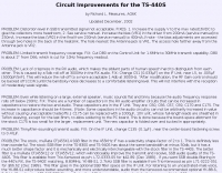 The page provides circuit improvements for the Kenwood TS-440S transceiver, addressing issues such as distortion in SSB signals, limited transmit frequency coverage, lack of crispness in RX audio, and flat audio response. The fixes include adjusting bias, cutting specific components, and changing capacitors to improve performance.
 -
 Demonstrates the _RoMac Automatic CW Identifier 2012_ software, a Windows application designed to automate station identification and provide a tuning pulser. It can send CW identification via a sound card's audio output or by keying a radio's manual CW jack using a serial port's DTR line. The software also supports CAT commands for various Kenwood, Yaesu, Flex, and Elecraft radios, enabling automatic mode and frequency changes for ID transmission. It integrates with USB audio-capable radios like the Icom 7300 and Yaesu FT-991, simplifying connectivity with a single USB cable. The application features a fully programmable interface, adjustable CW speed from **5 to 35 WPM**, and ID intervals from **5 to 30 minutes**. The integrated "Pulse Tuner" function allows for safe amplifier and antenna tuner adjustments by sending short audio tones or rapid CW keying, with an adjustable duty cycle from 1% to 100%. It offers compatibility with a wide range of transceivers and amplifiers, and a schematic for a basic sound card interface is included for users without existing setups.
 -
 137 kHz propagation analysis details ground wave and sky wave mechanisms, drawing heavily from **CCIR Rec. 368-6** for ground wave field strength predictions and **CCIR Rep. 265-7** for sky wave modeling. The resource presents field strength values for 1 W ERP at varying distances, considering ground conductivity and permittivity for ground wave, and ionospheric height (70km daytime, 90km nighttime) for sky wave. Key factors like ionospheric focusing (factor "D"), reflection coefficient ("RC"), and antenna ground pattern factors ("Ft", "Fr") are quantified for 137 kHz, enabling calculation of sky wave field strength. Practical coverage ranges are derived for 137 kHz, showing useful ground wave coverage up to 1600 km over seawater and 1100 km over average ground, assuming a -9 dBuV/m noise floor. Sky wave coverage extends beyond 2200 km during night-time and winter daytime, but is negligible during summer daytime at solar minimum. The document also compares ground wave and sky wave strengths, identifying crossover distances at 550 km (night-time), 750 km (winter daytime), and 1250 km (summer daytime), where interference fading can occur. Adjustments for solar maximum conditions are provided, indicating 2-11 dB higher sky wave values depending on distance and season.
 -
 Electroswitch Electronic Products specializes in the design and manufacture of various switch types, including rotary, toggle, pushbutton, and rocker switches, as well as encoders and indicator lights. The company provides commercial and MIL-spec compliant components, detailing features such as spring return, push/pull to turn, adjustable stop, concentric shaft, and keylock configurations for their rotary switch lines. Specific product series like the M5-series enclosed frame rotary switches are highlighted, demonstrating their engineering capabilities. The resource offers a Rotary Switch Configurator to assist customers in selecting appropriate components based on application requirements. It categorizes switches by construction, such as enclosed frame, open frame, military grade, sealed, subminiature, blade, and power options for rotary switches. Toggle switches are presented in miniature, full-size, military grade, and sealed variants, while pushbutton switches include ultra-miniature, miniature, standard, and sealed types. Further product details cover rocker switches in subminiature, miniature, and sealed configurations, alongside thumb switches. Encoder offerings include magnetic and mechanical types with options like concentric shafts and push-to-turn functionality. Indicator lights are available for both commercial rectangular panel mount and MIL-spec applications, featuring configurations such as Press-to-Test, Watertight, EMI Shielded, and Dimmable options.
 -
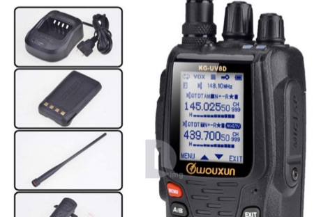 Wouxun KG-UV8D Standard Programming Software. Used to adjust or expand the frequency range to the full authorized range of the radio and not beyond. 134-174MHz 400-519MHz This software will Not add the 2.5kHz step.
 -
 A different implementation of the G7FEK HF multiband antenna with some adjustments and modifications
 -
 Linear amplifiers cold adjustments with network analyser (VNA)
 -
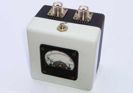 Measuring antenna current with and RF Ammeter