Search results
Query: antenna 40 m
Links: 559 | Categories: 11
Categories
- Antennas > 40M > 40 meter Dipole Antennas
- Antennas > 40M > 40 meter Loop Antennas
- Antennas > 40M > 40 meter Magnetic Loop Antennas
- Antennas > 40M > 40 meter Vertical Antennas
- Antennas > 40M > 40 meter Delta Loop Antennas
- Antennas > 40M > 40 meter Yagi Antennas
- Antennas > 40M
- Radio Equipment > HF Vertical Antenna > Butternut HF2V
- Radio Equipment > HF Vertical Antenna > Cushcraft R8
- Antennas > Morgain
- Antennas > Vertical
-
 A wire yagi antenna for 20 and 40 meters band suitable for outdoor and field day operations
 -
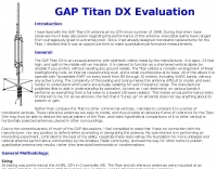 GAP Titan DX Evaluation, antenna for 10m 15m 20m 40m 80m
 -
 The Flower Pot Antenna project details a portable dual-band antenna primarily operating on 10 meters, with secondary resonance near the 30-meter band. Construction involves winding RG58 coaxial cable uniformly around a large plastic flower pot, approximately 70cm high with a 60cm top diameter. The design eliminates the need for radials, contributing to its compact and lightweight nature. Key construction steps include soldering the inner conductor to the shield at one end of the wound cable and connecting the wound cable's shield to the rig cable's inner conductor at the base. An LC network, comprising a variable capacitor (0-200pF) and an inductor (10 coils, 5cm diameter, 2mm wire), is inserted between the wound cable's inner conductor and the rig cable's shield. Tuning is performed with an antenna analyzer, adjusting cable length and the variable capacitor for optimal impedance on 10 meters. The antenna performs effectively when installed horizontally.
 -
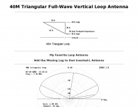 A 40 meters band full wave antenna project plan with model, adding the Missing Leg to the Inverted-L Antenna
 -
 This Delta Loop is a three-sided antenna suspended high in the air by vertical supports, such as tall evergreen trees. Recommended height is 40 feet or more at highest point, but higher is better.
 -
 Alinco's factory in Toyama, Japan, holds ISO9002/140001 certification, underscoring its commitment to quality manufacturing processes for amateur radio equipment. The company produces a diverse range of products, including HF transceivers, mobile VHF/UHF radios, handhelds, and scanners, serving both new and experienced operators within the ham radio community. Their product line extends beyond transceivers to encompass essential accessories such as antenna tuners and power supplies, which are crucial for complete station setups. These offerings support various operating environments, from portable field operations to fixed home stations, ensuring versatility for radio amateurs. Alinco, Inc. Electronics Division is headquartered at Yodoyabashi Dai-Bldg 13F, 4-4-9 Koraibashi, Chuo-ku, Osaka 541-0043 Japan, maintaining a global presence in the amateur radio market.
 -
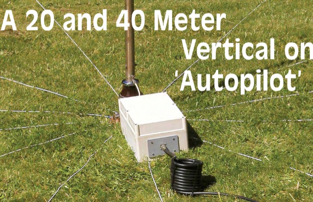 A 20 and 40 meter vertical on Autopilot by K6MHE PDF File
 -
 Short dipole antenna for 40 meter ham band. Can be put up in the space required for a 20 meter dipole.
 -
 A coil loaded dipole antenna for 40 and 80 meters band by I2CN
 -
 The 80-meter loop antenna, measuring 86 meters (282 feet) of wire, effectively operates across 8 HF bands from 80 through 10 meters, despite its length being a compromise for specific bands. This design prioritizes a "low enough" SWR across multiple bands, aiming for lower SWR values on higher frequencies due to increased feedline losses. A 200-ohm feedpoint impedance provides a workable SWR on every band, with feedpoint impedances ranging from 100 ohms for lower bands to 300 ohms for higher bands. Radiation patterns for the 80-meter loop, mounted at 15 meters high, show a maximum gain of 7.6 dBi at a 90-degree takeoff angle on 80 meters, and up to 12.9 dBi at a 10-degree takeoff angle on 12 meters. This configuration supports regional contacts on 80 meters and provides good DX performance on higher bands. Practical construction notes emphasize using robust supports like trees, ensuring wire slack with _egg insulators_ for wind resilience, and employing an oversized 2 kW 4:1 _balun_ to safely handle higher SWR conditions, even with 100W transceivers. Feedline losses are minimized using _LMR-400_ coax or ladder line, with power transfer efficiency between 80% and 95%. Antenna simulations were performed using _xnec2c_, and the provided NEC file is compatible with other NEC2 derivatives. The antenna is tunable on 6 of 8 bands with an internal ATU and all 8 bands with an external autotuner like the LDG AT-200 Pro.
 -
 A dual-bander for 80M and 40m. An Extended Double Zepp (EDZ) is a 5/4 wavelength center-fed dipole. This article will introduce the Half-Extended Double Zepp (HEDZ) which has characteristics that a lot of amateur radio operators should find quite interesting
 -
 Simple and cheap antenna for 40/80 meter band in Italian
 -
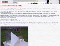 This Antenna is not really practical for AO-40 reception, but horn antennas have a number of qualities useful in microwave antenna testing and noise figure measurements.
 -
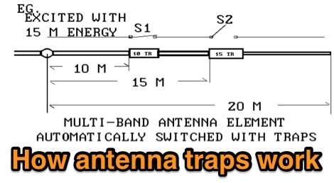 An interesting article about homebrewing antenna traps for multiband antennas by VE3GK
 -
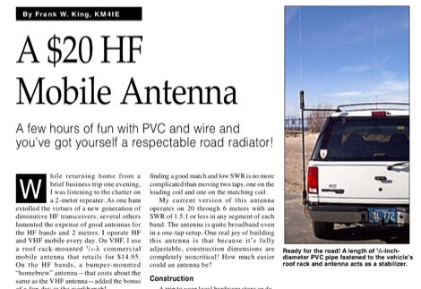 A few hours of fun with PVC and wire and you have got yourself a respectable road radiator. The antenna consists of little more than some PVC pipe topped by a RadioShack replacement whip antenna and a couple of coils made from a small roll of #14 house wire.
 -
 Drawings pictures and notes on a rotary dipole antenna for 30 and 40 meters band
 -
 One is an EFHWA for 20-40 meters, and the other is a matching unit for the antenna by n0lx
 -
 This antenna is intended as a simple, inexpensive solution for the newcomer to experiment across the 40m band (7.0-7.2MHz) when only restricted space is available
 -
 Modified version of the Telerana antenna which was orginially featured in the July 1979 issue of QST. The array is suspended within a framework made of fiberglass poles emanating from a central hub with the ends tied together with light weight rope around the perimeter. 10-15-20-30-40 meter band coverage
 -
-
 40 meters band Delta loop antenna plan that is vertically polarised
 -
 ZZ Wave Net is a 40 & 80 meter full wave loop designed to fit on a city lot. ZZ Antenna is a folded dipole bent into an inverted V loop
 -
 Over 30 distinct shortwave (SW) receiver models are reviewed, offering insights into their performance, features, and user experiences. These evaluations, contributed by readers of the Usenet newsgroup **Rec.radio.shortwave**, cover a wide array of portable and tabletop radios, including popular units like the Grundig YB-400, Sony ICF-SW77, and various Realistic DX series models. Each review details aspects such as frequency range, tuning steps, SSB functionality, antenna performance, and construction quality, often comparing them to other receivers or ham transceivers like the Icom 725. For instance, the Grundig YB-400 review highlights its 144-30000 kHz AM/SSB coverage, direct keypad entry, and 40 station memories, noting its useful narrow bandwidth and tone switch for adjacent signal separation. It also discusses the **SSB mode** stability and the limitations of its 1 kHz frequency resolution for precise zero-beating. The review further details antenna performance, including the effectiveness of the built-in whip, the provided 7m reel antenna, and the potential for overload with larger outdoor antennas. Other reviews delve into specific issues, such as the Sony ICF-SW77's frequency display inaccuracies and timer malfunctions, or the Realistic DX-342's compact size and surprisingly good MW DXing capabilities despite its analog tuning. The collection provides practical, user-generated feedback on sensitivity, selectivity, audio quality, and ergonomic features, helping shortwave listeners understand the real-world performance and quirks of these receivers.
 -
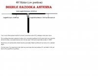 A double bazooka antenna plan for the cw portion of the 40 meter band
 -
 Demonstrates the construction and on-air performance of the _NB6Zep_ antenna, a modified 20-meter Extended Double Zepp design optimized for multi-band operation from 40 through 10 meters. The resource covers basic design principles, including dimensions of 66 feet horizontal and 5 feet vertical elements, and specifies open ladder line or TV twin lead for the transmission line. It details material selection for low-cost wire antenna construction, such as 18 AWG wire for the legs and ceramic or plastic insulators, along with practical tips for soldering connections and insulating against moisture. The author, NB6Z, shares insights from extensive _EZNEC_ modeling to optimize the antenna's total length for a 40-meter half-wave dipole footprint and feed line length for direct tuner connection. The article presents field results, including successful _PSK31_ contacts from Oregon to the East Coast on 40 and 30 meters with 50 watts, even at a low height of 6 feet. It provides detailed performance characteristics for each band, noting the _NB6Zep_'s highest gain (over 3 dB) and sharp, medium-angle lobes on 20 meters, which yielded strong DX reports to locations like Korea, Japan, and Argentina. For 17 and 15 meters, it describes a butterfly-like pattern with broad lobes, while 12 and 10 meters exhibit narrow, directional lobes in an "X" configuration. The author also shares personal experiences operating successfully for over a decade in an antenna-restricted environment using the NB6Zep and other stealth wire antennas.
 -
 The Bruce array is a simple, often-forgotten wire antenna array that is advantageous for 80 and 160 meters, where typical gain antennas are very large. This bi-directional broadside vertical array is only 1\4 lambda high and does not require a ground system. It offers substantially greater SWR bandwidth than the half-square or bobtail curtain. A 4-element Bruce array used by N6LF showed a gain of about 4.6 dB compared to a 1\4 lambda vertical with 8 elevated radials, with a 2:1 SWR bandwidth greater than 400 kHz. The antenna is simple and its dimensions are flexible.
 -
 Presents a catalog of **QRP** transceivers, antenna tuners, and related accessories for amateur radio operators. The product line includes the ZM-2 antenna tuner, designed for efficient impedance matching across HF bands, and the NW-series QRP transceivers, offering low-power CW operation. Additionally, the site details various ladder line insulators and specialized connectors, emphasizing robust construction for field deployment and home station use. Each product listing provides specifications, operational parameters, and pricing information. Compares the features of different **QRP transceiver** models, such as the NW-40 and NW-20, highlighting their respective band coverage and power output capabilities. The ZM-2 tuner's performance is detailed with typical SWR reduction figures for various antenna types, demonstrating its utility for portable and fixed stations. Customer testimonials and product images illustrate the practical application and build quality of EMTECH's offerings, providing insights into their durability and ease of integration into existing amateur radio setups.
 -
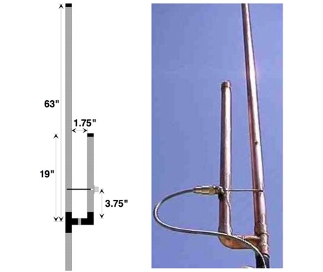 A simple dual band VHF UHF jpole antenna Projects by Dale Kubichek
 -
 This antenna is easy to build and suitable for broadband work, satellite work and terrestrial work.
 -
 A bazooka antenna project for the 7 Mhz, includes dimension for to homebrew your own bazooka for HF bands
 -
 Attic Fan dipole antenna that allow to operate QRP from 40 metres to 10 metres, specifically 40, 20, 17, 15 & 10 meter band
 -
 The N2CKH travel special 300 Ohm ladder line convertable antenna
 -
 Manual for R7, 10 12 15 16 20 30 40 meters band antenna
 -
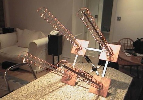 A homebrew project of a quadruple helix antenna system based on G3RUH 16 turn helix antenna for 2.4 GHz.
 -
 Catalogs a diverse array of Software Defined Radio (SDR) projects and realizations, systematically classified by their sampling methodologies and underlying hardware architectures. The resource delineates projects into categories such as those utilizing soundcard sampling of traditional transceiver audio outputs (Type Ia), mono soundcard sampling of intermediate frequencies (Type R1x-x-xx), stereo soundcard sampling of I/Q IFs (Type Q1x-x-xx), dedicated stereo audio ADC sampling of I/Q IFs (Type Q2x-x-xx), direct antenna RF signal sampling with off-the-shelf acquisition boards (Type R3x-x-xx), dedicated RF ADC sampling of analog IFs (Type R2x-x-xx), dedicated RF ADC sampling of direct antenna RF signals with ASIC-based processing (Type R4x-A-xx), FPGA-based processing (Type R4x-F-xx), and specialized IF chipsets combining ADC and DDC functions (Type Dxx-S-xx). Each entry provides a brief description, often including pricing, availability of source code, and specific hardware components like ADCs, DACs, DDS, and FPGAs. The compilation presents various practical applications, from PSK31 and Packet radio implementations to adaptations of the DRM standard for amateur radio bandwidths, such as Hamdream and WinDRM. It features specific hardware designs like the SoftRock-40 for the 40-meter band, the Firefly SDR for 30m and 40m, and more complex systems like the Quicksilver QS1R, which employs a 16-bit 130 Msamples/s ADC and an Altera Cyclone III FPGA. The resource also lists sample processing software, RF front-end designs, and academic/commercial SDR initiatives, offering insights into different approaches for I/Q conversion and digital signal processing in SDR systems.
 -
 This multiband wire antenna it is an off centre fed dipole, with 10 feet of vertical radiator, needs no tuner on 40m, 20m and 10m and works fine on all bands above 40m with a tuner, and even below 40m on 60m, and 80m.
 -
 Multiband Center-Loaded Off-Center-Fed Dipole (CL-OCFD) antenna that work on 80m 40m 30m 20m 15m 10m. The Center-Loaded Off-Center-Fed Dipole (CL-OCFD) antenna, developed by Serge Stroobandt, offers a versatile solution for amateur radio enthusiasts, covering multiple HF bands (80, 40, 30, 20, 15, and 10 meters) without the need for an antenna tuner. This innovative design utilizes a capacitor for resonance on the 80-meter band and a resistor to manage static charges. The CL-OCFD enhances bandwidth and simplifies operation, making it a significant advancement on OCF Dipole design.
 -
 Demonstrates the construction and performance of an updated ZS6BKW multiband dipole, a variant of the _G5RV_ antenna, specifically designed for HF operation. The article details a real-world installation using 13.5m copper wire elements and 12.2m of 450 Ohm ladder line, configured as a sloping inverted-V with the apex at 10m and ends at 4m above ground. It covers the critical aspect of impedance matching, incorporating an 8-turn choke balun at the feedline transition to RG-58U coax to mitigate RF common mode current. Measurements confirm favorable SWR readings below **1.3:1** on 7.1 MHz, 14.11 MHz, 18.06 MHz, and 24.8 MHz, indicating effective resonance across 40m, 20m, 17m, and 12m bands. The installation also shows usable SWR dips on 3.55 MHz (5:1), 29.02 MHz (2:1), and 50.84 MHz (3:1), extending its utility to 80m, 10m, and 6m with an antenna tuning unit. Initial on-air results report clear reception of stations over **5000km** away, validating its DX potential.
 -
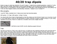 An easy to make trap dipole antenna for 40 and 20 meters
 -
 A delta loop wire antenna plan for the 7 MHz band (40 meters) that is quick to setup and work with
 -
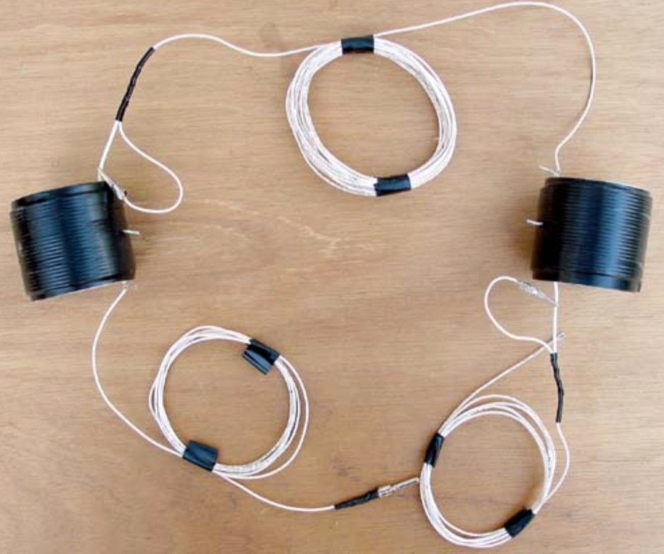
 Four band lightweight antenna, that rolls up into an small Grundig antenna case by N0LX
 -
-
 Selecting an appropriate antenna system for shortwave broadcasting involves evaluating various types based on performance, cost, and operational parameters. This resource details the critical specifications for broadcast antennas, including average and peak power ratings, directivity, takeoff angle (TOA), horizontal beamwidth, and gain, emphasizing that a 100-kW transmitter requires an antenna rated for 150 kW average and 400 kW peak. It clarifies that low TOA signals travel thousands of kilometers, while high TOA is for local coverage, and nearly all modern shortwave broadcast antennas are horizontally polarized. The article explores specific antenna types, such as Log-Periodic Antennas (LPAs), which offer wide frequency ranges (e.g., 2-30 MHz) and directional patterns with 11 dBi gain, costing from $20K to over $100K for multi-curtain versions. Dipole arrays, also known as curtain antennas, are prevalent in international broadcasting, featuring steerable beams (±15° and ±30°) and mode-switching capabilities to alter TOA, with high/low pairs costing over $1 million. Fan dipoles are noted for omnidirectional patterns, smaller size, and lower cost for low-power applications, while rhombics, though simple, require resistive termination and incur several dB of I2R losses. Balun considerations are crucial, as most communications baluns are not rated for the higher average and peak powers of AM broadcast transmitters. Modern shortwave antennas utilize durable materials like Alumoweld wire rope for radiators and support elements, avoiding copper, fiberglass, or materials prone to stretching or deterioration. Feeder systems for high-power stations often require tapered-line baluns to convert 50-ohm unbalanced power to 300-ohm balanced for connection to the antenna.
 -

-
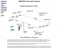
 The total length of this antenna is 41m, height is about 11m, and diameter of element is 2mm. JA7KPI modified this antenna originally used as Inverted-V type of 80m band Dipole. Works on 40 - 80 meters band with acceptable swr.
 -
 This page describes a homebrew 80/40 meter trap vertical antenna. Includes an interesting antenna raising system that allow easy setup and tuning.
 -
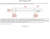
 The 30/40 meter **vertical antenna** project by IK4DCS details the construction of a shortened, self-supporting design, reaching a total length of 5 meters. The antenna incorporates a linear loading section and a coaxial cable trap for 30 meters, based on the "Antenne Volume 2°" text by Nerio Neri (page 223). The design uses six radials, three for each band, positioned at approximately 90° inclination and at least one meter above the roof or ground, connected via a 1:1 balun at the feed point. Mechanical construction utilizes aluminum tubing, with a 2.30-meter primary radiator section (30 mm diameter) joined to a second part using a Teflon insert and a PVC sleeve for rigidity. The linear load, approximately 3.70 meters long, accounts for a 30% physical shortening of the quarter-wave element. A capacitive load, made from three 50 cm radials, is integrated into the 40-meter top section for fine-tuning. Final adjustments involved radial inclination for 40 meters, as initial testing showed increased SWR and interference on 30 meters due to nearby resonant structures. The author emphasizes the importance of clear space for optimal performance and provides drawings and photos to clarify the build process.
 -
 Indoor multiband dipole with EZNEC data files for simulation and analysis. Includes details on construction, tuning, SWR plots, and software usage. This page includes two different dipoles, a first version for 20-10 meters and an extended version covering 40-10 meters allowing a full coverage of most used ham radio HF Bands.
 -
 This project started as a result of renewed interest in 40 meters coupled with the desire for an antenna system that would be more effective than the simple dipole.
 -
 Article by DK5WL describes a multi-band DX antenna for the 160m-40m amateur radio bands with low visibility but great performance for long distance communication.