Search results
Query: antenna 80 meter
Links: 220 | Categories: 2
Categories
-
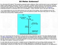
 This 80/160 meter antenna is constructed from six 12 foot aluminum tubes to form a slip-up mast antenna some 60 feet high by K0RWU
 -
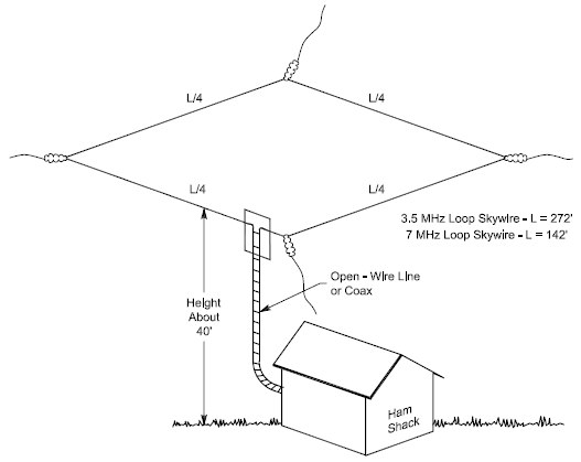 An horizontal full wave wire loop antenna for the 80 meters band by W4HM
 -
 The IK-STIC 2 is a vertical, all band, antenna that is over 25 feet tall yet weighs under 5 pounds. Based on a telescopic pipe or a fiberglass fishing pole, using a tuner it can easily cover the amateur radio HF bands from 40 - 10 Meters
 -
 The Joystick antenna was used many years ago as an all band vertical HF antenna under restricted space situations that would cover from 80 meters thru 10 meters with a tuner and was a great commercial success Some hams even had success with it on 160 meters.
 -
 A 40-meter reversible _Moxon rectangle_ antenna project details its construction and performance, featuring 51-foot long sides and 7.7-foot turned-in sections. The design incorporates a 16.5-foot boom, with elements spaced 1.1 feet apart, constructed from #14 covered wire. It utilizes two double-pole relays for switching between NE and SW directions, achieving F/B ratios up to 40 dB on CW and 30 dB on SSB, with distinct reflector stub settings for each mode. This antenna replaced a full-size 2-element Yagi, demonstrating comparable forward gain while offering superior F/B ratios and directional flexibility. _EZNEC_ modeling indicates only 0.2 dB less forward gain than the Yagi. The system uses no baluns, relying on half-wave feedlines and switched stubs for impedance matching. The antenna is tree-supported at 45 feet, with its effective radiation height modeled at 80 feet due to local terrain, enhancing its performance over a nearby lake.
 -
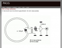
 VE3HCR article of a home made loop antenna for 80 meters band
 -
 This very large moxon antenna resonate on 80 40 and 10 meters, has been used for CQWW 2006 by a YU team project
 -
 The basic antenna is a vertical monopole, using elevated radials to complete the ground plane by k5oe
 -
 Here are construction plans of a Turnstile antenna that can be used for space communication on the 2 meter amateur radio band. Specifically for 145.80 mHz
 -
 A delta loop antenna project for the 40 meters band, include dimensions 80 meters band, with construction details, schematic and tuning instructions
 -
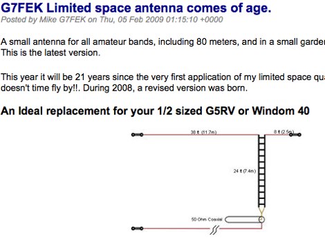 A small antenna for all amateur bands, including 80 meters, and in a small garden without the compromise. An ideal replacement for those half size antennas such as the 1/2 size G5RV and Windom 40
 -
 A really simple receiving antenna for 80 and 160 meter dxing by WA2WVL
 -

-
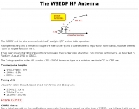 G3YCC article pn the W3EDP end-fed antenna for 80 to 20 meters bands
 -
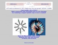 Mesh constructed with enamelled wire 0.5 mm diameter For installing a support (plastic rope 2 mm) is needed. Antenna used on Solomon Isl in 1995 H44/DJ9RB
 -
 This is a resonant, half-wave, vertical antenna. It takes up little space in the back yard, was designed for operation on a single frequency 80 meter PSK net, and is reasonably inexpensive to construct by Chuck Hines, K6QKL
 -
 Antenna data, and design note for this horizontal loop antenna resonating on 80 Meters by K0ZE
 -
-
 KN4LF article about a 1/4 wave fan inverted L antenna for 80 and 160 meters band
 -
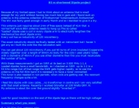
 This article describe a small single wire antenna running on the side of the building allow operations on 80 meters band
 -
 Doublet multiband antenna for 80 to 10 meters band by
 -
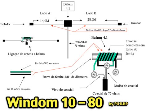 Project of a windom multiband antenna for 10 to 80 meters in portuguese
 -
-
 The G5RV antenna, a popular multi-band wire antenna, typically employs a center-fed design with a specific length of 300-ohm or 450-ohm open-wire line acting as an impedance transformer, feeding a coaxial cable run to the shack. Its overall length for 80-10 meters is approximately 102 feet (31 meters) for the flat-top section, with a 34-foot (10.36 meter) matching section. The original design by Louis Varney, G5RV, aimed for efficient operation on 14 MHz (20 meters) as a 3-half-wave antenna, with the matching section providing a good match to 50-ohm coax on that band. While the G5RV offers multi-band capability, its performance varies across bands, often requiring an antenna tuner for optimal SWR on bands other than 20 meters. The matching section's length is critical for its impedance transformation properties, influencing the feedpoint impedance presented to the coaxial cable. Variations like the G5RV Junior and ZS6BKW utilize different flat-top and matching section lengths to optimize performance for specific band sets or to achieve a lower SWR without a tuner on certain bands, demonstrating the adaptability of the basic G5RV concept.
 -
-
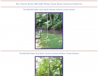
 Article on the HF dual band antenna with construction details and how to add 160 meters to the HF2V
 -
 An easy to build single wire antenna for 160 and 80 meters with a better than 2 to 1 swr across the 80 meter band by K5GP
 -
 A 40 ft vertical dipole antenna that can cover HF Bands from 80 to 10 meters winding a dipole in a 12m HD telescoping fiberglass pole
 -
 Homebrew a vertical antenna for 40 and 80 meters band based on popular HF2V model by DL7JV
 -
 A vertical antenna for 40 and 80 meters band with no need of antenna tuner, based on a telescopic fiberglass mast of 48 feet by N8NSN
 -
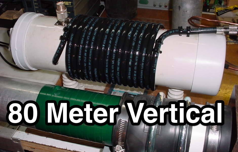
 Presents the design and construction of the OK2FJ Bigatas, a portable, automatically tuned vertical antenna covering 80 through 10 meters. It details two distinct control systems: one utilizing BCD band data from Yaesu FT-857/897 transceivers, and another employing voltage level sensing for the Yaesu FT-817. The resource provides specific instructions for building the antenna's radiating element, loading coil with switchable taps, and the control circuitry, emphasizing the use of readily available components. The article outlines the physical construction of the antenna, including the use of duralumin tubes for the radiator and a PVC tube for the coil form. It specifies coil winding details, tap points, and the integration of radial wires for ground plane operation. The control electronics section provides schematics and component lists for both the BCD decoder (using a 74LS42 IC) and the voltage comparator (using an _LM3914_ bargraph driver), enabling rapid, automatic band switching without the minute-long tuning delays common in other systems. Crucially, the antenna achieves rapid band changes, with typical SWR values centered on common operating segments, such as **3.7 MHz** for 80m SSB. It also discusses modifications for CW operation on 80m and the trade-offs between antenna efficiency and full-range automatic tuning on higher HF bands, where manual adjustment of radiator length is suggested for optimal performance on 15m, 12m, and 10m. The resource includes construction photos and a discussion of cable requirements for reliable operation.
 -
 JJ0DRC's HF multi-band delta loop antenna project, initially conceived during the waning peak of Cycle 23, addresses the common challenge of achieving effective DX operation from a small residential lot in Japan. Dissatisfied with a ground plane antenna's performance in SSB pile-ups, the author sought a beam-like solution without a tower, drawing inspiration from a JJ1VKL article in CQ Ham Radio Sep. 2000. The antenna, constructed in October 2000, employs two 7.2-meter fishing rods (37% carbon fiber, reinforced with cyano-acrylate glue and aluminum tape) and 1mm enameled wire, fed by an Icom AH-4 external antenna tuner. While the exact beam pattern remains unmeasured, JJ0DRC observed a significantly higher callback rate compared to dipole antennas, particularly on higher bands. The system's circumference length of 15-20m is crucial for maintaining a good beam pattern across HF bands, though performance on lower bands like 80m, 40m, and 30m becomes less directional as the length deviates from a full wavelength. Ongoing maintenance addressed degradation issues, including aluminum tape cracking and wire breakage at connection points due to strong winds (often exceeding 10-15m/s in winter). The author reinforced rod connections with IRECTOR PIPE SYSTEM components and INSU-ROCK ties, and improved wire attachment methods using Cremona rope and epoxy bond to enhance durability.
 -
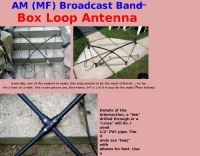
 A ranking of receiving antennas based on noise being evenly distributed in all directions. These rankings are most accurate in the frequency range of AM broadcast, 160 or 80 meter bands
 -
 A multiband antenna that can work from 80 to 10 meters in this illustrated docuemnt by G8ODE
 -
 3 Band vertical Marconi-antenna for the bands 40, 80, 160 meters with a ground net of wires as radials.
 -
 An inverted V antenna for 40-80 with loading coils. This antenna is a full size on 40 and a shortened 80 by KG0ZZ.
 -
 A schematic design of the W3DZZ antenna in portugues with description of trap building
 -
 YF1AR 80 to 40 meter vertical antenna project
 -
 An easy to build single wire antenna for 160 and 80 meters with a better than 2 to 1 swr across the 80 meter band
 -
 A three-frequency multi-band dipole that can be extended easily to additional bands. This article includes a multiband fan-dipole antenna for 80-40-20-10 meter band.
 -
 This is a popular antenna design as the performance is very good across the HF bands and requires little or no tuning. It is a dipole fed off center with a 4:1 current balun at the offset feedpoint. The antenna shown covers 80, 40, 20 and 10 meters with 15 meters and WARC bands
 -
 An home made trapped dipole antenna for 40 and 60 meters band by 2E0HTS
 -
 Homebrew a 1/4 wave 80 meter vertical using aluminium tubing
 -
 A self supporting vertical antenna for 80 meters by W9OY include pictures and construction details
 -
-
 An 87ft inverted L portable antenna working on 80 40 30 20 15 meters band
 -
 Operating a ZS6BKW antenna often involves understanding its lineage from the _G5RV_ design, with specific modifications by ZS6BKW to optimize performance on several bands. Through computational analysis and field measurements, the antenna's dimensions were refined to allow operation on 10, 12, 17, 20, and 40 meters without an antenna tuner. For 80, 30, and 15 meters, a tuner is necessary, though efficiency on 30 and 15 meters is noted as not particularly high. The physical configuration consists of two 13.755-meter radiating elements fed by a 12.20-meter section of 450-ohm ladder line. Tuning the antenna on the 20-meter band is critical, and any deviation in the ladder line's characteristic impedance necessitates recalculating the element lengths. The design is also referenced in the 12th edition of _Rothammel's Antennenbuch_, page 219. Proper common mode current suppression is crucial at the transition from ladder line to coaxial cable. This can be achieved with a common mode choke, such as several turns of coax wound into a coil or over a ferrite toroid like an Amidon T130. While a 1:1 balun is an option, it may introduce issues.
 -
 A vertical antenna specifically designed to work with the 80 meter CW beacon keyer
 -
 Yet another G5RV antenna plan to build a G5RV Antenna for 80 to 10 meters usage
 -
 A 90-foot vertical antenna constructed from **aluminum irrigation tubing** is detailed, focusing on its innovative raising and lowering mechanism. The resource describes a **45-foot ginpole** system, allowing a single operator to erect or lower the antenna in minutes. It covers the mechanical design, including the pivot base, insulated joints for the tubing sections, and guy wire attachment points. The antenna consists of two 30-foot sections of 4-inch tubing and one 30-foot section of 2-inch tubing, stacked with the smaller diameter at the top. The electrical design incorporates PVC "condulet" boxes at the 30-foot and 60-foot points, housing relays to change the effective height for multi-band operation on 160, 80, 40, and 30 meters. Ferrite rod inductive chokes are used for DC control and to tune out gap capacitance. The antenna is fed with 1000 feet of open wire line, connected to a matching transformer comprising stacked toroids and a coaxial/toroidal balun. Grounding is achieved with a 3x3 foot grid of 16-gauge tinned copper wires with soldered crossovers.