Search results
Query: antenna length
Links: 269 | Categories: 0
-
 Wound on a 3 foot length of PVC pipe, the long loopstick antenna was an experiment to try to improve AM radio reception without using a long wire or ground.
 -
 One of the most important considerations when designing and building a Yagi antenna is the method used to attach the elements to a boom. This is true because the boom influences the electrical length of the elements. In this article JH Reisert explain with drawings techniques on mounting yagi antenna elements to a boom
 -
 The total length of the inverted L is 240 feet, which is 7/16th of a wave length long. It has a 92 foot horizontal linear load section 1 foot above ground that terminates into a home-brewed parallel network tuner by KN4LF
 -
 A homemade Magnetic Loop antenna from a spare 3m length of RG213 working from 30m to 15m with a 130pF tuning capacitor
 -
 A shorten Dual-Band Dipole with overall length of about 11 m. For this antenna traps are substituted by inductors, in order to cover the 10 & 40 m. Bands.
 -
 A High Efficiency Extended Length Mobile Antenna The antenna itself is 3.42 meters or 11 feet 2 inches long from the top of the mounting spring to the tip.
 -
 End-Fed Half-Wave Antennas (EFHWAs) are analyzed for their utility in portable QRP operations, emphasizing their simplicity, efficiency, and predictable radiation patterns compared to other portable antenna types. The discussion contrasts EFHWAs with vertical antennas, random length wires, and center-fed dipoles, highlighting the common pitfalls of each, such as ground system dependency for verticals and feedline issues for dipoles. The article details the electrical half-wavelength calculation using the formula L (Ft) = 468/F(MHz) and explains how EFHWAs can be resonant on harmonic frequencies, enabling multiband operation. Various deployment configurations are presented, including the inverted L, inverted Vee, sloping wire, and vertical setups, each with specific advantages for radiation angle and polarization. For instance, a vertical EFHWA offers a low angle of radiation suitable for DX contacts without requiring an extensive ground system. The resource also addresses the counterpoise requirements, suggesting a quarter-wavelength wire or connection to a metallic structure for decoupling. A schematic diagram for a simple parallel-tuned circuit tuner, based on the _Rainbow Bridge/Tuner_ design, is provided, detailing component values for 30 and 40 meters, including a 6 microhenry toroidal inductor and a 20-100 picofarad mica compression capacitor. The tuner's adjustment process for SWR matching is also outlined.
 -
 It is very easy to create a simple 1/2 wave dipole, all you need is some lengths of wire such as the core of some mains flex or even a straightened out metal coat hanger, some co-ax cable and a connector for your scanners antenna input
 -
 This PDF document, authored by KT4QW in October 2004, details the construction and modeling of a dual-band, horizontally polarized hanging rectangular loop antenna for **10 and 17 meters**. The design, adapted from *The ARRL Handbook*, utilizes _NEC4WIN95_ software for scaling and optimization, targeting a 50 ohm feedpoint impedance. The resource includes a bill of materials, step-by-step construction instructions, and a discussion of the antenna's radiation characteristics. It presents NEC-generated elevation and azimuth patterns, comparing the loop's performance to a half-wave horizontal dipole at the same height and frequency. The 17-meter element is centered at 18.140 MHz for low SWR across the phone band, while the 10-meter element is centered at 28.500 MHz. Construction involves 14-gauge stranded copper wire and Schedule 40 PVC spreaders, with the total wire length calculated by the formula: Length in feet = 1005/MHz. The feedpoint impedance can be adjusted by modifying the rectangular aspect ratio. The document specifies hoisting the antenna to at least a half-wave above ground for testing. It notes that a balun was tested and found to have no measurable effect on SWR or radiation characteristics. A 2-meter scale model is presented to illustrate the physical design, and a "rotator" string is incorporated for directional adjustment up to 90 degrees.
 -
 WorldRadio Article on Petlowany antennas base on this principle: if a length of wire is wound into a spiral-shaped coil and excited by a radio frequency current connected to the innermost portion of the coil, it will then, and only then, exhibit RF characteristics that closely approximate those of a resonant linear wire of the same length
 -
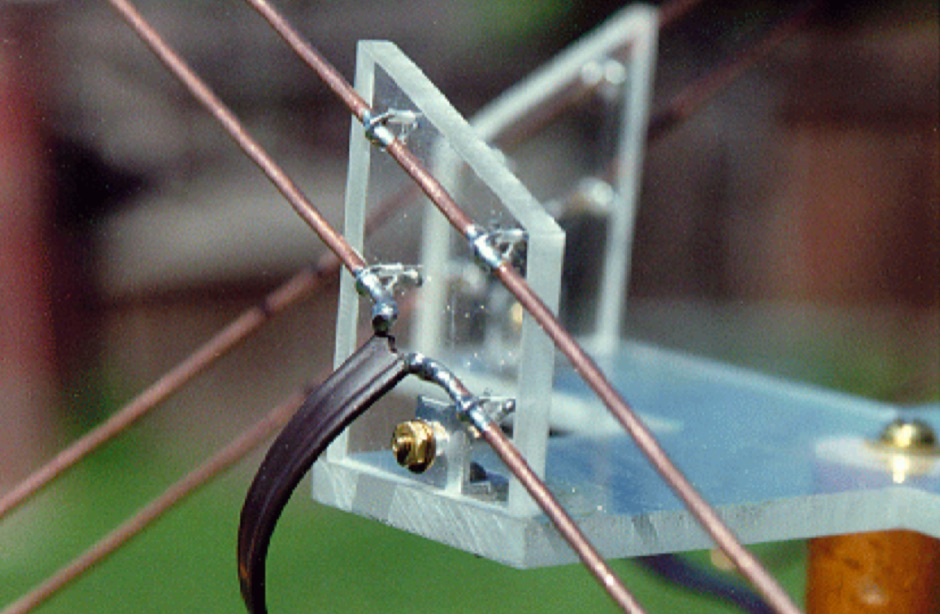 The ultimate satellite Omni Antenna by Howard Sodja, W6SHP. The Lindenblad antenna consists of four half wave folded dipoles slanted 30 degrees to the horizon, oriented 90 degrees to each other in azimuth, spaced 0.3 wavelength apart
 -
 A potpourri of 160-Meter vertical antennas and modeling issues, inverted-L, 3-element parasitic array, 1/4-wavelength monopole
 -
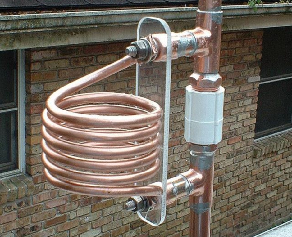
 The octoloop antenna is a length of 25 pair telephone wire inside an octagonal loop shield of 3/4 hard copper pipe
 -
 The Super J Pole antenna is a co-linear vertical consisting of a number of half wave length vertical elements separated with half-wave length stubs (Tuning stub) feed with a folded matching stub by vk6ysf
 -
 The document details the optimization and construction of the _Maria Maluca_ antenna, a compact 6-band (20m-6m) directional beam. It presents a comparative analysis of shortwave antenna principles, highlighting the efficiency gains achieved by using an open feeder line and tuner as a resonant unit, contrasting this with the losses associated with traps or capacitive loads in multiband antennas. The resource specifically revisits an older South American 2-element design for 10, 15, and 20 meters, applying modern NEC-based software to develop a six-band version. Performance data is meticulously tabulated, showing impedance, free space gain, gain at 12m height, elevation angle, and front-to-back (F/B) ratio for each band from 20m through 6m. For instance, on 15m, the antenna achieves 5.1 dBd free space gain and 13.72 dB F/B ratio. The construction section provides practical guidance on element assembly using aluminum pipes and hose clamps, detailing the use of a heavy-duty glass fiber reinforced polyamide rod for electrical separation and bending strength. It also specifies the use of 450-ohm _Wireman_ line CQ 552 for the transmission line. The document includes diagrams for rod fixing, an air-wound balun, and a vertical elevation diagram for the 15m band, illustrating its DX qualification. It also discusses the antenna's suitability for portable and expedition operations, noting its compact transport dimensions (max 1.50m length, 12 lb weight) and quick assembly time (under 15 minutes). The author, Dipl.Ing. Helmut Oeller, DC6NY, is identified as a source for material kits.
 -
 The G5RV antenna, a popular multi-band wire antenna, typically employs a center-fed design with a specific length of 300-ohm or 450-ohm open-wire line acting as an impedance transformer, feeding a coaxial cable run to the shack. Its overall length for 80-10 meters is approximately 102 feet (31 meters) for the flat-top section, with a 34-foot (10.36 meter) matching section. The original design by Louis Varney, G5RV, aimed for efficient operation on 14 MHz (20 meters) as a 3-half-wave antenna, with the matching section providing a good match to 50-ohm coax on that band. While the G5RV offers multi-band capability, its performance varies across bands, often requiring an antenna tuner for optimal SWR on bands other than 20 meters. The matching section's length is critical for its impedance transformation properties, influencing the feedpoint impedance presented to the coaxial cable. Variations like the G5RV Junior and ZS6BKW utilize different flat-top and matching section lengths to optimize performance for specific band sets or to achieve a lower SWR without a tuner on certain bands, demonstrating the adaptability of the basic G5RV concept.
 -
 Design your owm HF shiortened dipole. Includes a diagram of a lumped-constant loaded dipole antenna that is intended to fit in available space, rather than requiring a full 1/2 wavelength, at a specified frequency
 -
 Presents the design and construction of the OK2FJ Bigatas, a portable, automatically tuned vertical antenna covering 80 through 10 meters. It details two distinct control systems: one utilizing BCD band data from Yaesu FT-857/897 transceivers, and another employing voltage level sensing for the Yaesu FT-817. The resource provides specific instructions for building the antenna's radiating element, loading coil with switchable taps, and the control circuitry, emphasizing the use of readily available components. The article outlines the physical construction of the antenna, including the use of duralumin tubes for the radiator and a PVC tube for the coil form. It specifies coil winding details, tap points, and the integration of radial wires for ground plane operation. The control electronics section provides schematics and component lists for both the BCD decoder (using a 74LS42 IC) and the voltage comparator (using an _LM3914_ bargraph driver), enabling rapid, automatic band switching without the minute-long tuning delays common in other systems. Crucially, the antenna achieves rapid band changes, with typical SWR values centered on common operating segments, such as **3.7 MHz** for 80m SSB. It also discusses modifications for CW operation on 80m and the trade-offs between antenna efficiency and full-range automatic tuning on higher HF bands, where manual adjustment of radiator length is suggested for optimal performance on 15m, 12m, and 10m. The resource includes construction photos and a discussion of cable requirements for reliable operation.
 -
 This resource details the computer-optimized design of the _ZS6BKW_ multiband dipole, an evolution of the classic _G5RV_ antenna. It begins by referencing the original 1958 RSGB Bulletin article by Louis Varney G5RV, explaining the operational principles of the G5RV's flat-top and open-wire feedline on 20m and 40m, noting its impedance transformation characteristics for valve amplifiers of that era. The article then transitions to the rationale for optimizing the design for contemporary solid-state transceivers requiring a 50 Ohm match. The core of the project involves using computer modeling to determine optimal lengths for the flat-top and matching section, aiming for a VSWR of less than 2:1 on multiple HF bands. It discusses the process of calculating feedpoint impedance based on antenna length and frequency, referencing professional literature from Professor R.W.P. King at Harvard University. The analysis also considers the characteristic impedance (Z(O)) of the open-wire line, identifying a broad peak of adequate values between 275 and 400 Ohms. Specific design parameters for the improved ZS6BKW are presented, including a shorter flat-top and a longer matching section compared to the original G5RV, with a velocity factor of 0.85 for the 300 Ohm tape. The article confirms acceptable matches on 7, 14, 18, 24, and 28 MHz bands when erected horizontally at 13m, and also discusses performance in an inverted-V configuration, noting frequency shifts. The author, Brian Austin ZS6BKW, emphasizes the antenna's suitability for modern 50 Ohm coaxial cable without a balun.
 -
 JJ0DRC's HF multi-band delta loop antenna project, initially conceived during the waning peak of Cycle 23, addresses the common challenge of achieving effective DX operation from a small residential lot in Japan. Dissatisfied with a ground plane antenna's performance in SSB pile-ups, the author sought a beam-like solution without a tower, drawing inspiration from a JJ1VKL article in CQ Ham Radio Sep. 2000. The antenna, constructed in October 2000, employs two 7.2-meter fishing rods (37% carbon fiber, reinforced with cyano-acrylate glue and aluminum tape) and 1mm enameled wire, fed by an Icom AH-4 external antenna tuner. While the exact beam pattern remains unmeasured, JJ0DRC observed a significantly higher callback rate compared to dipole antennas, particularly on higher bands. The system's circumference length of 15-20m is crucial for maintaining a good beam pattern across HF bands, though performance on lower bands like 80m, 40m, and 30m becomes less directional as the length deviates from a full wavelength. Ongoing maintenance addressed degradation issues, including aluminum tape cracking and wire breakage at connection points due to strong winds (often exceeding 10-15m/s in winter). The author reinforced rod connections with IRECTOR PIPE SYSTEM components and INSU-ROCK ties, and improved wire attachment methods using Cremona rope and epoxy bond to enhance durability.
 -
 This is a simple calculator for solving the antenna wire catenary between to end points given the design wind speed, mass per unit length of the wire, wire diameter and Gross Breaking Strength of the wire.
 -
 Presents a comprehensive guide for constructing a broadband Hex Beam antenna, a popular directional array for HF operation. This design offers a compact footprint and excellent gain characteristics, making it suitable for limited space installations while providing significant performance advantages over omnidirectional antennas. The resource details the specific dimensions for a five-band Hex Beam covering 20, 17, 15, 12, 10, and 6 meters, emphasizing the critical element spacing and wire lengths required for proper resonance and pattern. It outlines the construction of the center post, spreaders, and wire elements, along with the feed point assembly, ensuring proper impedance matching. The project aims for a forward gain of approximately **5.5 dBi** on most bands, with a front-to-back ratio often exceeding _20 dB_. Building this antenna requires careful measurement and assembly, but the resulting performance provides a substantial upgrade for DXing and contesting.
 -
 This article refers mainly to the old Cushcraft 1/4 wavelength AV series of antennas (12AVQ, 14AVQ etc) hence the references to radials. The R series (R5, R7 etc) are 1/2 wavelength antennas, and the radials are NOT 1/4 wavelength resonant.
 -

-
 The ZS6BKW wire antenna, a variant of the G5RV, utilizes a specific 13m (42.6 ft) length of 450-ohm window line as its matching section, feeding a 28.5m (93.5 ft) flat-top element. This design aims for lower SWR on 40m, 20m, 17m, 12m, and 10m compared to a standard G5RV, often achieving SWR values below 1.5:1 on these bands without an antenna tuner. The feedpoint impedance transformation provided by the window line allows for direct connection to 50-ohm coax on multiple bands. F4FHH's experience involved constructing the ZS6BKW and evaluating its performance against an _OCF dipole_ (Off-Center Fed) on various HF frequencies. The article includes observations on SWR readings and operational effectiveness, highlighting the ZS6BKW's suitability for multi-band operation. The antenna's overall length, including the flat-top and window line, is approximately **41.5 meters** (136 feet), making it a significant wire antenna for fixed station use. Comparative analysis with the OCF dipole provided practical insights into the ZS6BKW's advantages and limitations, particularly concerning bandwidth and tuner requirements.
 -
 The Grid Yagi (or Grid Quad) is a high performance yagi antenna that can be built with readily obtainable inexpensive materials. Described here is a 6 element 2 meter version with a boom length of about 1 wavelength, shown
 -
 Based on DL6UW Yagi antenna's design-formula The forward gain is 13.6 dBi (about 11.5 dBd) and it's pretty small, about 1,5 m in length
 -
 The half wave dipole antenna is a simple and practical antenna model that consists of a half wavelength long centre fed conductor.
 -
 Helical antennas invented by John Kraus give a circular polarized wave. They are one of the easiest to design. Find a tube with a circumference equal to one wavelength, and wrap wire in a helix spaced a quarter wavelengt
 -
 The Crossed Field Antenna (CFA) is one of the applications of Correction of Maxwell's Equations which was used over 150 years ago which was proved these days that the Magnetic Field Source is only the Displacement Current not the Conduction Current . These Corrections was made by an Egyptian Doctor Engineer Fathi Kabbary , who reached the New Correct Theory which shows that the height and efficiency of the antenna doesn't depend on the wavelength
 -
 Operating a ZS6BKW antenna often involves understanding its lineage from the _G5RV_ design, with specific modifications by ZS6BKW to optimize performance on several bands. Through computational analysis and field measurements, the antenna's dimensions were refined to allow operation on 10, 12, 17, 20, and 40 meters without an antenna tuner. For 80, 30, and 15 meters, a tuner is necessary, though efficiency on 30 and 15 meters is noted as not particularly high. The physical configuration consists of two 13.755-meter radiating elements fed by a 12.20-meter section of 450-ohm ladder line. Tuning the antenna on the 20-meter band is critical, and any deviation in the ladder line's characteristic impedance necessitates recalculating the element lengths. The design is also referenced in the 12th edition of _Rothammel's Antennenbuch_, page 219. Proper common mode current suppression is crucial at the transition from ladder line to coaxial cable. This can be achieved with a common mode choke, such as several turns of coax wound into a coil or over a ferrite toroid like an Amidon T130. While a 1:1 balun is an option, it may introduce issues.
 -
 Loop antennae have been used from ELF to UHF since the beginning of radiocommunications. At low frequencies, the main problem for loop antennae is to have enough sensitivity; the antenna being very small respect to the wavelength the collected energy is also small. To increase the output level the loop may be made resonant, so loosing it%u2019s intrinsic aperiodic characteristics.
 -
 This project will enable you to build a monoband long wire inverted vee with 3/4 wave length sides that will have a bit of gain
 -
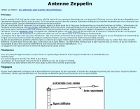 It consists of a radiating wire with a length equal to the half-wave of the fundamental frequency for which the antenna is cut.
 -
 Presents a detailed construction guide for a **Quadrifilar Helix Antenna** (QHA) optimized for 137 MHz, specifically for receiving weather satellite transmissions. The resource outlines the author's experience building previous QHA designs, highlighting challenges with tuning and nulls, and then focuses on a refined design by John Boyer, documented by Steve Blackmore, which proved easier to build and yielded superior reception. The guide provides precise element dimensions, including 1.5m of 32mm PVC pipe for the mast and 8mm soft copper tubing for the helix elements. It specifies lengths for horizontal tubes (190mm, 90mm) and helix elements (903mm, 1002mm), along with instructions for drilling, assembly, and forming a **balun** by wrapping RG58 coax around the mast. The text emphasizes critical steps like ensuring elements are square and twisting in the correct direction to avoid phase issues. It includes references to original QST articles by Buck Ruperto (W3KH) and the WxSat program for decoding satellite transmissions, contextualizing the antenna's purpose. The article concludes with a sample NOAA 12 image from September 1998, demonstrating the antenna's reception capabilities.
 -
 This resource details the conversion of an 80m elevated vertical antenna to include 160m operation, focusing on a relay-switched design over a trap-based approach. It presents specific feedpoint impedance values, such as **32 ohms** for 80m and **14 ohms** for 160m, and discusses the challenges of SWR drift encountered with the prior trap system during RTTY contesting. The article thoroughly explains the design choices for elevated radials, referencing _N6LF QEX data_ to debunk common myths regarding radial length and height, demonstrating that non-resonant radials can offer superior current uniformity. The construction section provides practical insights into building the vertical, including guying strategies, material selection from scrap pipe, and weatherproofing the relay assembly. It highlights the use of a common mode choke for the relay switching line, measuring approximately 5K ohms on both 160m and 80m, and details the L/C matching network's role in achieving a 50-ohm match at the end of a 300-foot RG-11 run. The author describes a precise VNA-based radial trimming procedure, achieving resonant values within a 3 KHz range. The content emphasizes the practical application of theoretical antenna principles, particularly concerning the interaction between the vertical element, cap hats, and the matching network. It offers a candid assessment of component selection, such as using junkbox parts and acknowledging the need for future upgrades to static drain resistors. The article serves as a comprehensive case study for advanced antenna builders tackling multi-band vertical designs.
 -
 Demonstrates the design and construction of a 9-element Yagi antenna for the **70 cm band** (432 MHz), based on the DK7ZB concept. The resource details EZNEC+ calculations for a single antenna, providing gain, sidelobe suppression, and front-to-back ratio figures. It also presents a comprehensive analysis of stacking two such antennas, including optimal stacking distance (1000 mm) and the resulting performance enhancements for the stacked array, such as an increased gain of 17.03 dBi. The article includes detailed drawings, wire file dimensions in millimeters, and azimuth/elevation plots for both single and stacked configurations. Practical construction steps are documented with original photographs, illustrating element mounting, the **28 Ohm matching system** using two quarter-wave 75 Ohm transmission lines, and the critical N-connector wiring. It also covers the iterative process of fine-tuning the driven element length to achieve a return loss of 20 dB, validating the EZNEC+ simulation results with actual measurements.
 -
 A simple quarter-wave length vertical for 40m band using a 12 m spiderpole
 -
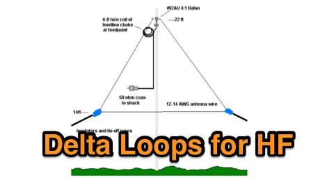 Planning and modelling Delta Loop antennas for all the ham radio HF bands include calculated wire lengths at each mid-band
 -
 Presents a construction project for a linear-loaded 40-meter rotatable dipole, detailing the design evolution from mid-element coils to 300-ohm twinlead loading. It covers material selection, including repurposed fishing poles and EMT conduit, and outlines the assembly process for the antenna elements and mounting plate. The resource provides specific measurements for element lengths and linear loading sections, along with SWR plots demonstrating the antenna's resonance at 7.035 MHz with a 1.1:1 SWR, and bandwidth up to 7.120 MHz below 2:1 SWR. The article documents the antenna's performance during various RTTY and CW contests, including the SARTG RTTY and SCC RTTY contests in August 2006, and the ARRL DX CW and CQWW WPX RTTY contests in February 2007. It reports successful operation at 500-1000W, noting improved performance after replacing a faulty coax cable. Specific DX contacts from British Columbia, including stations in Europe and South Africa, are listed, illustrating the antenna's capability despite its shortened length and relatively low height of 55 feet. The content highlights practical considerations such as weatherproofing the connections and supporting the fiberglass elements to prevent sagging. It also includes a brief comparison to an inverted-V at similar height and a ground-mounted vertical, noting the rotatable dipole's quieter reception. The author shares insights into the iterative design process and tuning adjustments made to achieve optimal resonance.
 -
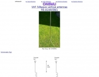 By Guy, de ON6MU, At VHF, both the 1/4-wavelength monopole and the 5/8-wavelength monopole antennas are widely used.
 -
 The ZS6BKW antenna, a popular multiband wire antenna, offers improved band matching compared to the traditional G5RV. This construction guide details the process, beginning with specific dimensions: 13.11 meters (43 feet) for the 450-ohm ladder line and initial dipole arm lengths of approximately 14.8 meters each. It emphasizes the critical role of an _antenna analyzer_ for accurate tuning, particularly for determining the velocity factor of the ladder line and achieving a 1:1 impedance match. The article outlines the materials required, including a 1:1 current balun, 450-ohm window line, wire for the dipole arms, and a 50-ohm non-inductive resistor for testing. It provides a step-by-step procedure for cutting the ladder line to its electrical half-wavelength, explaining how to calculate the velocity factor using measured and free-space frequencies. For instance, a measured 50-ohm impedance at 12.54 MHz with a calculated free-space half-wavelength frequency of 11.44 MHz yields a velocity factor of 0.91. Final adjustments involve hoisting the antenna to its operational height and fine-tuning the dipole arm lengths to achieve optimal SWR, specifically targeting 14.200 MHz. The _ZS6BKW_ design is noted for its performance on 80m, 40m, 20m, 10m, and 6m, though it is not optimized for 15m operation. The author, _VK4MDX_, shares practical tips for durable construction using stainless steel wire and cable clamps.
 -
 Demonstrates the design and construction of a compact, portable multi-band mini-delta loop antenna, specifically optimized for /P (portable) operations from remote locations like Scottish islands. The resource covers the theoretical underpinnings of half-wave loops, contrasting closed and open configurations, and then details the application of a folded dipole principle to achieve a 50-ohm match for direct coax feed. It presents empirical formulas for calculating element lengths, considering the velocity factor of common wire types, and provides a detailed example for a 20m (14.175 MHz) version. The article includes a comprehensive table of dimensions and allowances for a five-band (20m, 17m, 15m, 12m, 10m) mini-delta beam, along with construction hints for the central support and balun. It specifies a 1:1 trifilar balun wound on a ferrite rod and describes the antenna adjustment process using an _MFJ-259B Antenna Analyser_. Initial test results indicate an SWR of 1:1 at resonance and a bandwidth of approximately 240 kHz on 20m, even at a low height of five feet above ground. The distinctive utility lies in its focus on a practical, easily deployable beam antenna for portable DXing, offering a viable alternative to more complex or larger arrays.
 -
 The Vee Beam antenna project presents a versatile solution for hams, enabling operation across all eight High Frequency bands (80m to 10m) with significant gain on 20m to 10m. This easy-to-construct antenna utilizes two long wires at an angle, enhancing directional performance and minimizing ground losses. With a low visual profile, it is discreet and effective for various applications. The design allows for optimal leg lengths and included angles, ensuring robust performance while maintaining simplicity in construction and operation. The V Beam antenna is an aerial that you can use on all eight High Frequency amateur bands (80, 40, 30, 20, 17, 15, 12 and 10m) with an antenna tuner, and which gives significant gain on the five bands from 20 to 10 meters band.
 -
 One of the most useful antennas in the repertoire is the Marconi or quarter wave grounded vertical antenna. Its invention made it possible to halve the length of antennas, simplifying communications, especially at HF and below.
 -
 Demonstrates the design principles and performance characteristics of **corner reflector antennas**, emphasizing their high gain and directional properties. It covers critical design factors such as the corner angle and the spacing between the radiating dipole and the reflector vertex. The resource explains how reducing the corner angle increases gain but lowers feed impedance, making matching more challenging. Practical angles of 90 degrees or 60 degrees are discussed, with 90 degrees offering easier impedance matching despite slightly lower gain. Details key design considerations, including reflector side length exceeding two wavelengths and reflector width greater than one wavelength for a half-wave radiator. It specifies reflector construction using wire netting, sheet metal, or parallel metal spines spaced less than 0.1 wavelength. The article provides a table with general dimensions for UHF and VHF bands, noting typical impedance values of 50 to 75 ohms and expected SWR of 1.7:1 on the lower band edge. Adjustable radiator-to-vertex spacing is highlighted as crucial for final tuning.
 -
 This document details the design and construction of a Vinecom 6N4 dual-band Yagi antenna for the 50MHz (6-meter) and 70MHz (4-meter) amateur radio bands. The antenna features 9 total elements (4 elements for 50MHz, 5 elements for 70MHz) on a 4.236-meter aluminum boom. Computer simulations using MMANA software predict 7.21 dBd gain on both bands with front-to-back ratios of 16.01dB (6m) and 15.37dB (4m). The design uses 12.7mm diameter elements mounted on a 32mm square boom, weighing 5.7kg total. Practical measurements with an MFJ-269 analyzer confirmed good SWR performance across both bands after element length adjustments.
 -
 The G5RV multiband HF antenna, designed by Louis Varney (G5RV) in 1946, is a popular compromise antenna offering good overall performance on most HF bands when paired with an external antenna tuner. The basic full-size G5RV measures 102 feet across the top for 80 through 10 meter operation and is fed at the center via a 34-foot low-loss feed-stub. This interaction between the radiating section and the feed-stub facilitates matching across 80-10 meters with a standard tuner, often eliminating the need for ladder line directly to the shack. The antenna's design center frequency is 14.150 MHz, configured as a 3/2-wave dipole on 20 meters, with its 102-foot length derived from long-wire antenna formulas. Construction details emphasize the matching section, which can be open wire, ladder line (window-type), or TV twin lead. Each type has a specific velocity factor (VF) affecting its physical length for an electrical half-wave on 14 MHz; for instance, open wire requires 33.7 feet (VF 0.97), ladder line 31.3 feet (VF 0.90), and TV twin lead 28.5 feet (VF 0.82). The article provides formulas for calculating these lengths and discusses the antenna's behavior on individual bands, from 3.5 MHz where it acts as a shortened dipole, to 28 MHz where it functions as two three-half-wave long-wire antennas fed in-phase. Practical construction notes include recommendations for vertical descent of the matching section, sealing the coax junction, providing strain relief, and winding a coaxial choke coil to mitigate common mode current. The resource also presents dimensions for double-size (204 ft) and half-size (51 ft) G5RV versions, along with their corresponding matching section lengths for various line types, making it a versatile reference for hams considering this classic wire antenna.
 -
 A bowtie antenna is a type of antenna that reputedly provides higher gain at lower radiation angles than a center-fed dipole antenna at heights considerably less than 1/2 wavelength above ground.
 -
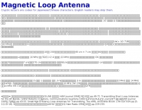 Although a magnetic loop antenna(aka small loop antenna) is very compact, its efficiency is close to a half-wavelength dipole if carefully built.