Search results
Query: calculation
Links: 89 | Categories: 3
-
 A multi tool Windows program that has been designed to offer the EMC RF and Radio Engineer a large variety of tools for Attenuation calculation, VSWR analysis, FIR Filter calculations, EMC system configuration, Radar testing , RF Filter calculation and much more without the need of a live internet connection.
 -
 The Tri-pole antenna, a clever modification of a standard dipole, allows for dual-band operation by integrating a third element. This design effectively shortens the overall dipole length by 10 to 20 percent, simplifying antenna rotation and offering a compact footprint. KK4OBI's article delves into the operational principles, using a 6 and 10-meter Tri-pole as a primary example, and provides comprehensive instructions for constructing any Tri-pole antenna within the 6 to 15-meter range. Key to the Tri-pole's performance is its off-center feed, necessitating a common mode choke at the feed point for optimal tuning and reduced noise. The author outlines a methodical approach to determining element dimensions, starting with a vertical element frequency calculated as 0.47 times the sum of the desired upper and lower band frequencies. This calculation, along with K-values derived from trend lines, guides the initial lengths for the horizontal arms, demonstrating how a 10m-6m Tri-pole can achieve a total horizontal length 78% shorter than a conventional 10-meter dipole. Tuning and balancing are critical, with the article detailing adjustments to arm lengths and the vertical element to achieve balanced SWR values, as validated through 4NEC2 simulations. Radiation patterns are analyzed at various elevations, showing gains around 5.7 dBi and favorable take-off angles for DX contacts. Construction details specify aluminum tubing dimensions, U-bolts, and an SO-239 connector, emphasizing the importance of a ferrite-based choke for wideband operation.
 -
 This paper presents the method of calculating the maximum usable frequency (MUF) and field strength of radio waves reflecting 2 times at the F2 ionosphere layer under inhomogeneous conditions of the ionosphere. The comparison between predicted and measured MUF has shown that the proposed method significantly increases the accuracy of calculation MUF.
 -
 DF0WD/DL4YHF's Longwave Overview details amateur radio operations on the 135.7 to 137.8 kHz segment in Germany. The author outlines the "inofficial" European band plan, specifying segments for QRSS, TX tests, beacons, conventional CW, and data modes. Early LF activities at DF0WD began with a 20-watt CW transmitter, later upgraded to a homemade linear transverter capable of 100 watts, driven by an Icom IC706 on 10.137 MHz. The station's antenna system includes a 200-meter wire, approximately 10 meters above ground, supported by football field light-masts. Despite its length, the antenna's efficiency is noted as very low due to the immense wavelength of about 2.2 km. The author's experience highlights the significant challenge of achieving effective radiated power (EIRP) on LF, estimating DF0WD's EIRP at around 80 milliwatts based on field strength measurements from PA0SE. DF0WD/DL4YHF has successfully worked numerous countries on 136 kHz CW, including DL, F, G, GI, GM, GU, GW, HB9, HB0, LX, OE, OH, OK, OM, ON, OZ, PA, and SM. The author also mentions ongoing efforts to log contacts with CT, EI, LA/LG, and to complete a two-way QSO with Italy, demonstrating persistent activity on this challenging band.
 -
 This page delves into the Inverted V antenna, a source of myths among ham radio operators. The author explores the behavior of this antenna type with a focus on a 20m half-wave dipole positioned 10m above the ground. From Pythagoras to high school math, the article simplifies the calculation of dimensions and angles for setting up an Inverted V antenna. It includes a spreadsheet for calculating hypotenuse length and angles, crucial for antenna setup. Additionally, it provides insight into the radiation pattern of a 'flat' half-wave dipole at 10m height. Useful for hams planning to optimize their antenna setup. In Norwegian.
 -
 Calculate distance, bearing and more between Latitude/Longitude points. This page presents a variety of calculations for latiÂtude/longiÂtude points, with the formulas and code fragments for implementing them.
 -
 Determining the characteristic impedance (Z) of an unknown coaxial cable, a common challenge for many radio amateurs, can be resolved with a straightforward method. The impedance of a coaxial cable is derived from its inductance and capacitance, and importantly, these values are independent of the cable's length or the operating frequency. This means that measuring a random length of cable, such as 20 meters, provides sufficient data for calculation. The core of this technique involves an LC-meter to obtain the inductance (L) in microHenries (uH) and capacitance (C) in microFarads (uF). The impedance is then calculated using the formula Z = L/C. For instance, a measurement yielding L=1.2uH and C=450pF (0.00045 uF) results in an impedance of 51.6 Ohms, closely matching **RG-58** specifications. Similarly, a TV coaxial cable with L=1.8uH and C=320pF (0.00032 uF) calculates to 75 Ohms. While the accuracy of this method, depending on the LC-meter's tolerance, is approximately 10%, it proves sufficiently precise for practical determination of unknown coaxial cable impedance, as noted by Makis, SV1BSX, who credits Cliff, K7RR, for the formula's dissemination.
 -
 Coax Velocity Factor in Baluns, Does it Matter? Test results show coaxial cable velocity factor does not always enter into stub length calculations especially in the world of Baluns
 -
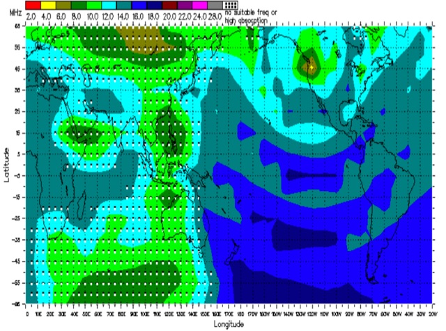
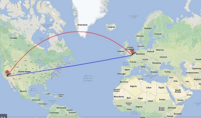
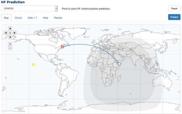 Online HF Communication prediction system provided by the Australian Governament Buerau of Metereology allow to predict usable frequency rage for radiocommunications between two stations allowing to specify frequency and date range. This tool allow calculation with different methods and algorithms
 -
 This article shares the author's experience with building antennas. After putting a large magnetic loop project on hold, they decided to try a base-loaded vertical antenna. The author explains how they chose to design a new antenna from scratch, aiming for a frequency of 7 MHz. They describe the calculations needed to find the right coil inductance and how they used 3D-printed parts for the construction. The article wraps up with results from their initial tests, showing good communication on different bands and highlighting the success of their design.
 -
 Here is a formula and calculator for creating a loaded (shortened) quarter wave vertical or balanced dipole. The calculation refers to either a loaded 1/4 wave or a loaded dipole
 -
 First released in 1988, _SWLog_ is a comprehensive suite of applications providing logging and remote control for both amateur radio and shortwave, utility, and broadcast listening. It integrates program schedules from sources like _HFCC_, _ILGRadio_, and _EiBi_ for broadcast reception, while also linking with amateur radio logbooks such as _ClubLog_, _eQSL_, _QRZ_, and _LoTW_. The software supports radio control for various transceivers, including _Flex_, Icom, Yaesu, and Kenwood, alongside interfaces like _FLRig_, _OmniRig_, and _HamLib_. Mobile applications for Android and iOS facilitate on-the-go logging and remote control, seamlessly transferring logs without manual ADIF export. _SWLog_ leverages an enterprise-grade relational database (SQL Server) for robust data management and analytics, enabling features like mapping QSOs by band or state. It offers specific integrations for _POTA_ monitoring, displaying active spots with real-time propagation and automatic radio tuning. The application's scalability allows multiple users to log to a centralized database, suitable for Field Day or DXpeditions. The user interface features modern aesthetics with light, dark, and gray themes, the latter optimized for outdoor visibility during activities like _POTA_ or _SOTA_. The Plus Edition, available for an annual fee, expands capabilities with advanced QSL integration, additional map providers, and enhanced propagation calculations using _VOACAP_.
 -
 This article describes the construction of a 9,50 m long dipole for the 30 m band (10.1 MHz to 10.15 MHz). It was designed to be mounted ca. 6Â m above ground inside an attic. The calculations were performed by OE1MEW
 -
 The HB9CV antenna calculator aids amateur radio enthusiasts in designing antennas for VHF and UHF bands. By inputting the working frequency, users can obtain crucial dimensions like dipole lengths and distances. The tool, based on the HFSS antenna model, provides data on impedance, VSWR, and gain, optimizing front/back radiation ratios. It includes tips for fine-tuning using a Г-matching balun and compensating capacitor, ensuring effective performance and minimal VSWR for enhanced radio communications and direction finding.
 -
 The Saturn PCB Toolkit is the best freeware resource for PCB-related calculations you can find. It incorporates many features that PCB designers and engineers are in regular need of like current capacity of a PCB trace, via current, differential pairs and much more. Please download our PCB Toolkit today for free and enjoy!
 -
 Coil64 (Coil32) is a versatile tool for calculating single-layer inductance coils used in various electronics, such as matching circuits and amplifiers. The online calculator enables users to estimate the number of turns, winding dimensions, and select the appropriate wire type for home-brewed RF inductors. It employs Bob Weaver's equation, factoring in wire corrections, and allows for the calculation of Q-factor and self-capacitance. Coil64 is compatible across multiple platforms, including Windows, Linux, Mac-OS, and Android.
 -
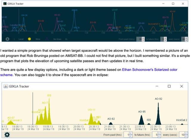 KlaTrack is a Windows-based software application designed to assist amateur radio operators with satellite communication by predicting spacecraft visibility. It provides a simple interface to determine when specific satellites will be above the local horizon, a critical factor for successful two-way contacts via amateur radio satellites. The program processes _Two-Line Element_ (TLE) data to calculate orbital mechanics, offering a practical tool for satellite operators to plan their operating windows. It supports real-time tracking and displays essential pass information. This utility simplifies the complex task of satellite tracking, allowing operators to focus on making contacts rather than manual orbital calculations. While specific gain figures or distances are not quantified, the software's core function directly supports achieving successful satellite QSOs by providing precise pass predictions. It is particularly useful for operators engaging in activities like working the International Space Station (ISS) or other low-Earth orbit (LEO) satellites, where short pass times and precise timing are crucial for maximizing contact opportunities.
 -
 This article describes the phases for the construction of a Yagi antenna. The calculations of the parameters are made using 4NEC2 software. This type of antenna is used for transmissions and receptions of electromagnetic waves. The project shown here refers to the frequency of 433.92 MHz.
 -
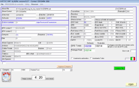 ARTIC is a specialized software tool designed for amateur radio operators participating in VHF contests, offering log checking functionalities. It specifically caters to Italian and Swiss VHF contests, such as the IAC (Italy) and SWAC (Switzerland), ensuring adherence to contest rules and accurate score calculation. The software is developed by IK2FTB and provides a dedicated platform for post-contest log analysis. This resource includes download links for various versions of the ARTIC software, with updates noted for different contest years and rule sets. For instance, versions like ARTIC 2022 and ARTIC 2023 are available, reflecting ongoing development and adaptation to evolving contest parameters. The page also features links to related contest resources and information, providing a centralized hub for VHF contesters to manage their logs and verify their entries.
 -
 Online antenna calculator for a basic 3 elements yagi uda directional antenna. The described antenna design offers a front-to-back ratio of at least 20 dB, a gain exceeding 7.3 dBi, and a bandwidth (SWR < 2) of approximately 7% around the center frequency. It has an input impedance of 50 ohms when using a straight split dipole, which can be substituted with a folded dipole of the same length, increasing the impedance to 200 ohms. A matching balun is required for coaxial feeder connection, and the boom should be made of a dielectric material, like wood.
 -
 This DIY guide details constructing a 5-element Yagi antenna for VHF frequencies. Yagi antennas offer directional signal transmission/reception compared to omnidirectional ones. The guide covers material selection (aluminum, screws, etc.), design using software or formulas, and step-by-step assembly including cutting elements, drilling holes, and attaching the coaxial cable. While calculations are provided for a 146 MHz design, adjustments are necessary for different frequencies. Safety precautions and potential result variations are emphasized.
 -
 Presents a detailed construction guide for a 9 dB, 70cm collinear antenna, utilizing readily available _RG58/U_ coaxial cable and PVC pipe for housing. The resource outlines the critical calculations for ½ wavelength sections at 444 MHz, incorporating the coaxial cable's velocity factor of 0.66, which yields a section length of 223 millimeters. It specifies the preparation and soldering of eight such half-wavelength sections, each cut to 231mm to allow for trimming, forming the core of the array. Further instructions detail the integration of a ¼ wave element (169mm #16 solid wire) at the top and a ¼ wave aluminum tube (160mm, 5/16 inch) at the bottom, crimped to the feed point's braid. The guide also addresses RF common mode current suppression by suggesting the use of _FT50-43_ toroids on the feedline. Final assembly steps cover mounting the antenna within ¾" PVC pipe using a wooden dowel, waterproofing connections, and initial SWR checks. The article also discusses scaling the design for different element counts and other VHF/UHF bands.
 -
 A 5/8 λ antenna, often thought to be ideal for all frequencies, has unique characteristics that don't universally apply. First introduced for medium-wave radio, it works optimally at 225° antenna length over ideal ground, yielding high efficiency. However, at VHF and higher frequencies, it offers no advantage over other antennas due to real ground conditions and complex matching requirements. DIY calculators provide only rough estimates, useful as a starting point for simulations, not for precise builds.
 -
 This article focus on the radiation angle of vertical antennas and the fundamentals of electromagnetic wave propagation. The calculation of antenna length at 145 MHz is followed by an explanation of electromagnetic wave speed and the link between wavelength, frequency, and velocity. Author discusses the 5/8th wave vertical antenna, namely its performance and the influence of radiation angle on signal transmission. Figures and analogies demonstrate how different antenna types produce distinct radiation patterns. This highlights the importance of selecting the right antenna for a certain purpose, such as local traffic or dxing. The article discusses a variety of factors that affect antenna performance, including SWR, propagation conditions, and equipment dependability
 -
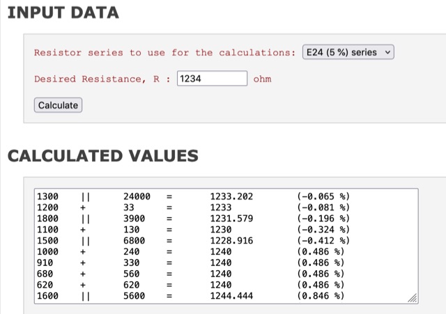 If you need a non-standard resistor value you could probably realize a close match using two resistor. If you use two resistor in series it is quite easy to figure out which values give the best match; on the other hand, using a parallel connection it is not so easy (at least for me) to find a good combination. This resistor calculation tool shows which combinations of two resistors (series or parallel) gives a match better than the closest standard value, for the E12 (10%), E24 (5%) and E96 (1%) series.
 -
 This program simplifies the complex jumper calculations for the PRF1520 radio, which can be a pain to determine manually. It supports common crystal frequencies and channel spacings, advising if a desired frequency is achievable. A recent feature allows determining unknown frequencies of a newly obtained radio by setting the jumper positions and other parameters.
 -
 Delta loop antennas, particularly the 30 meter variant, offer unique advantages in terms of vertical polarization and omni-directional coverage. The construction process detailed by VE3VN highlights common mechanical and electrical challenges faced by amateur radio operators. Key design considerations include minimizing interaction with existing contest band antennas, achieving low elevation angles for DX chasing, and ensuring the antenna remains off the ground for agricultural clearance. The article provides specific measurements, such as the loop's height and feed point impedance, which are critical for optimizing performance. The use of NEC modeling software illustrates the importance of accurate resonance calculations, revealing how proximity to the tower affects both pattern and impedance. This practical account serves as a resource for hams looking to build effective antennas while navigating typical construction hurdles.
 -
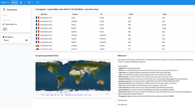 Demonstrates a cloud-based suite of tools for amateur radio operations, eliminating local software installation. The platform integrates a comprehensive logbook with import/export functionality, an _eMap_ application displaying DX spots, user locations, and grayline data, alongside a dynamic band map derived from DX cluster information. It also provides a _vQSL_ system for QSL management and a mailbox with QSO verification. Users can access a Web DX cluster to monitor spots and _DXCC_ status, or connect via Telnet using external programs like _Logger32_ or Ham Radio Deluxe. The cluster supports advanced spot filtering by QRG, spot call, spot from, and origin, with configurable mail alerts based on IARU zone filters. Additional features include a real-time chat for skeds, azimuth/distance calculations from a user's QTH (with QRA locator), a search engine for spot and logbook databases, a band status matrix, and a propagation tool for MUF calculations, leveraging data from N0NBH.
 -
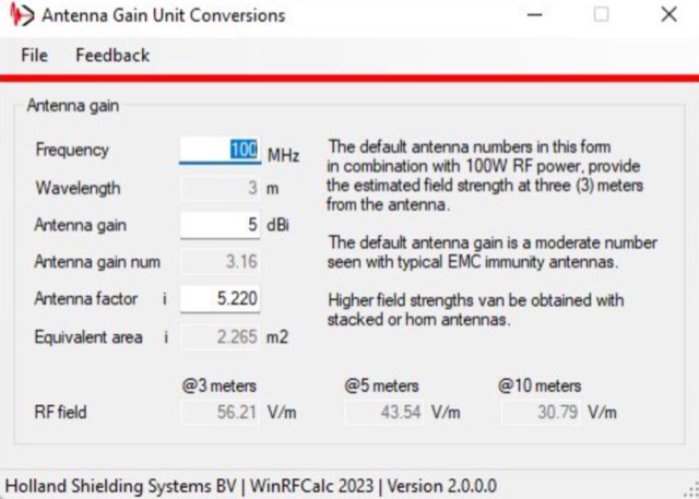
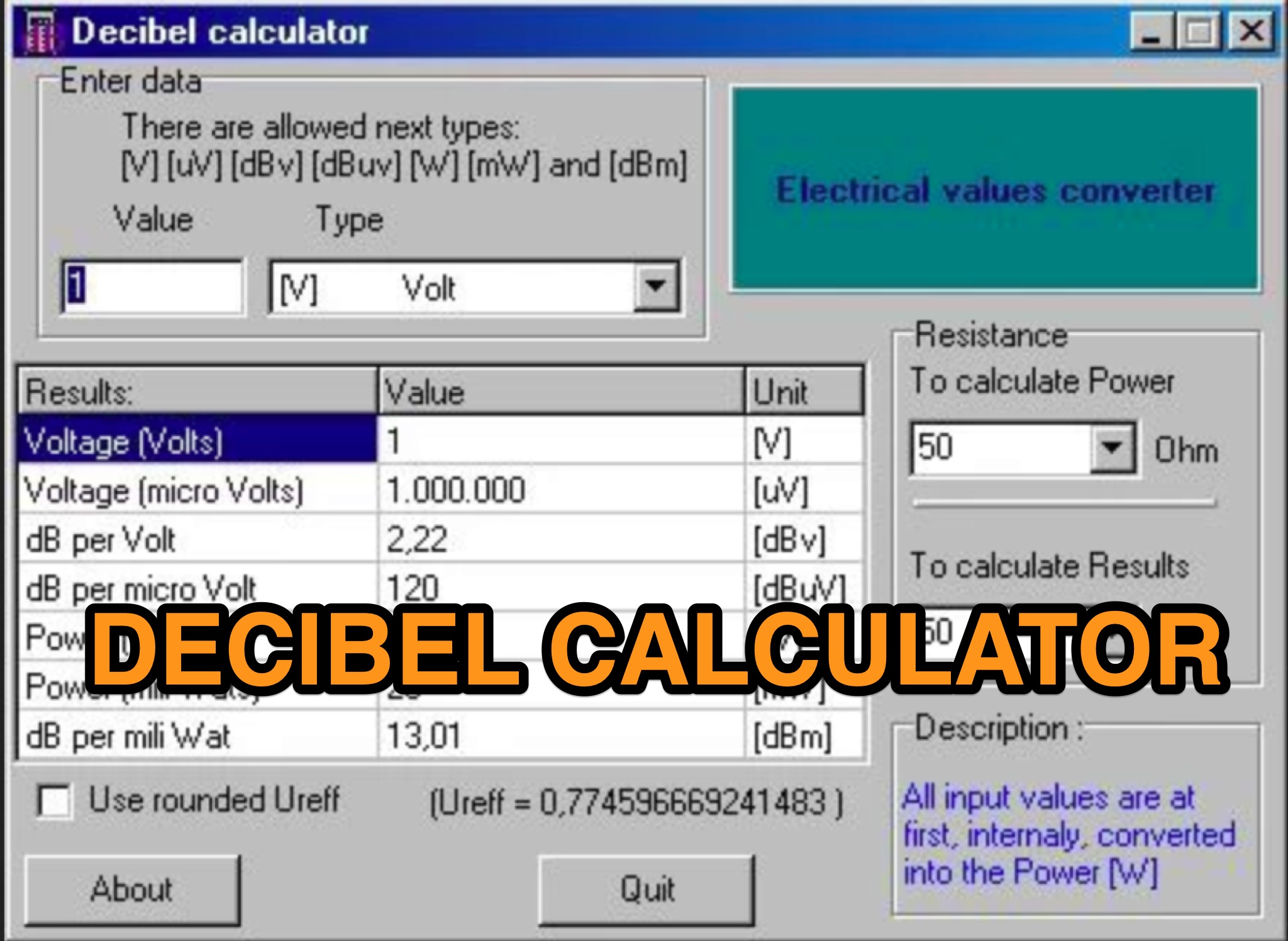 Learn how to easily convert between different units like dBu, dBm, W, mW, V, and uV with the dBCalc application. This small windows program allows ham radio operators to quickly check conversions using input and output resistance. It's a useful tool for anyone dealing with electronic measurements and calculations. Best of all, dBCalc is free to use, making it a convenient solution for amateur radio enthusiasts. This tool simplifies complex conversions and helps hams optimize their equipment setup.
 -
 This article explores the powerful features of AutoEZ as an Excel application working with EZNEC antenna modeling software. The article demonstrates how variables, equations, and formulas enable versatile antenna design and automatic optimization. Through practical examples including dipoles, inverted vees, delta loops, and monopoles, the author shows techniques for achieving resonance, implementing transmission line resonators for broadbanding, and optimizing antennas across frequency ranges. The step-by-step demonstrations cover unit conversion, coordinate calculations, segmentation considerations, and SWR optimization. This practical guide illustrates how AutoEZ extends EZNEC's capabilities, making complex antenna modeling more efficient and accessible.
 -
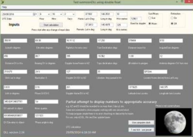 The purpose of the Moon tracking DLL is to provide an easily used platform for the calculation of the position of the sun or the moon and to provide the associated information often required for amateur radio operators interested in EME. DLL works with any of Windows versions of Delphi, Visual Basic, C and versions.
 -
 The Beam project offers various features for controlling antenna rotators, including support for 2 or 4 line LCD displays, software or hardware clocks, open collector drives for azimuth and elevation control, and internal calculations for tracking the sun and moon. It can also track satellites and supports "Flip Mode" for inverted antennas. The 4-line version provides detailed readouts while the 2-line version offers a more compact display. New versions now support PWM and I2C H-bridge modes for adjustable speed control at the end of a move.
 -
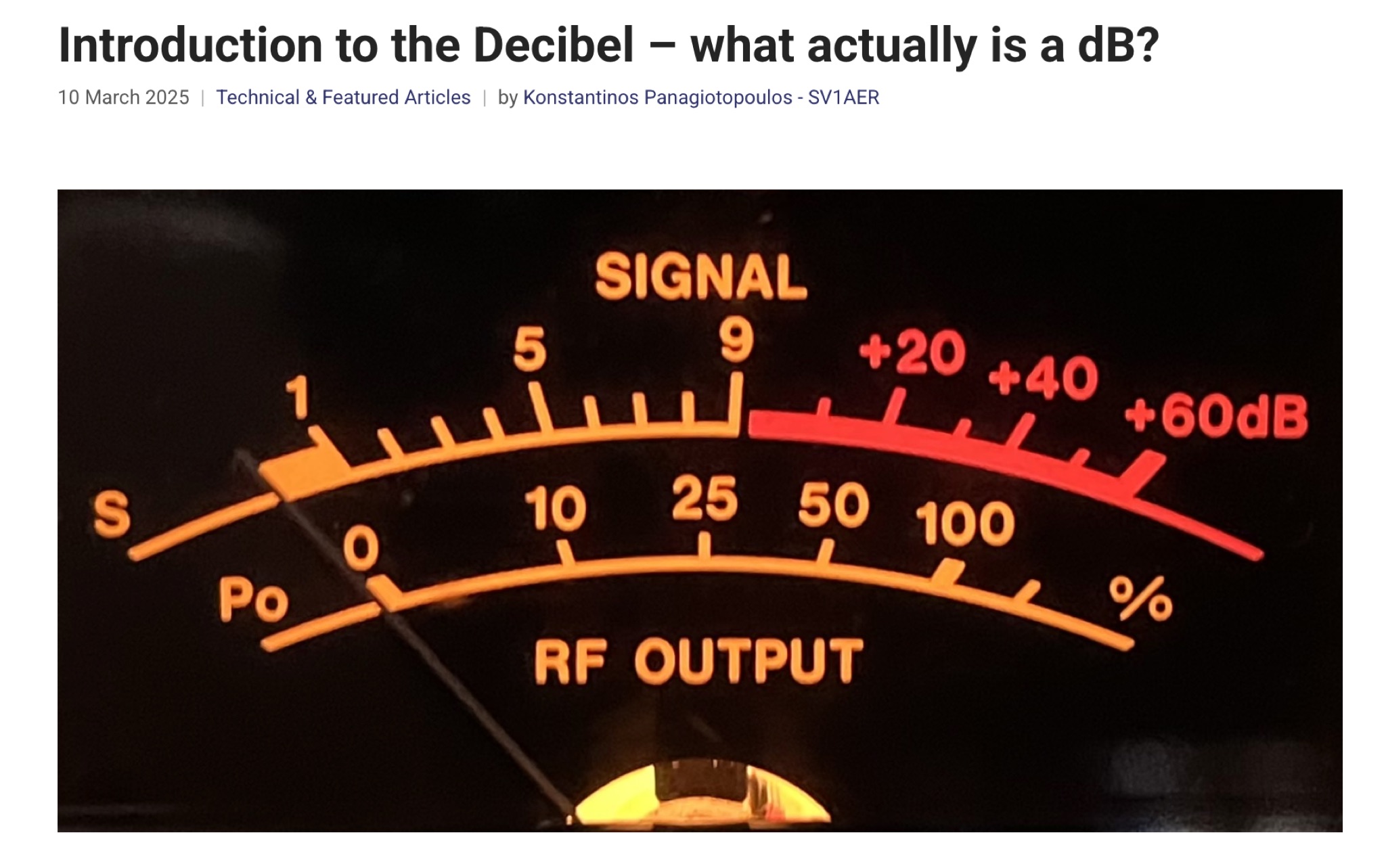 This article provides a comprehensive introduction to the decibel (dB), its logarithmic nature, and its applications in power, voltage, and antenna gain calculations. It explains how dB simplifies comparisons in electronics, telecommunications, and audio perception. The author clarifies key mathematical concepts, including power ratios, voltage doubling, and absolute levels like dBm and dBV. The discussion on S-units and antenna system gain is particularly relevant for radio amateurs. Overall, this is an informative and well-structured guide to understanding and applying decibels in technical fields.
 -
 A full-wave delta loop antenna, approximately 141 feet in total wire length for the 40-meter band, offers a low angle of radiation, which is highly advantageous for DX operations. This design, optimized for both 30m and 40m, leverages a specific circumference calculation of 1005/F, ensuring resonance on both bands through a simple switching mechanism. The antenna's configuration enhances long-distance communication, making it a practical choice for hams with limited space. The resource details the construction process, including the use of a _Ceramic Knife Switch_ for band selection and an _RG-11_ matching section to achieve optimal impedance. It outlines the precise loop lengths required for each band, along with tuning secrets to ensure efficient operation. Requiring a minimum height of 12 feet, this antenna can be supported by a single mast or tree limb, making it suitable for suburban installations where stealth or space constraints are a factor.
 -
 This project outlines a simple, cost-effective 40m band HF dipole antenna design, ideal for beginners. Constructed with insulated copper wire and a 1:1 balun, it offers a 50-ohm impedance, suitable for both 40m and 15m bands due to the harmonic relationship. Calculations account for a K factor, ensuring optimal length and performance. Antenna modeling with 4NEC2 confirms practical access to both bands, though real-world results may vary. Lightweight materials and straightforward assembly make it an accessible and versatile amateur radio solution.
 -
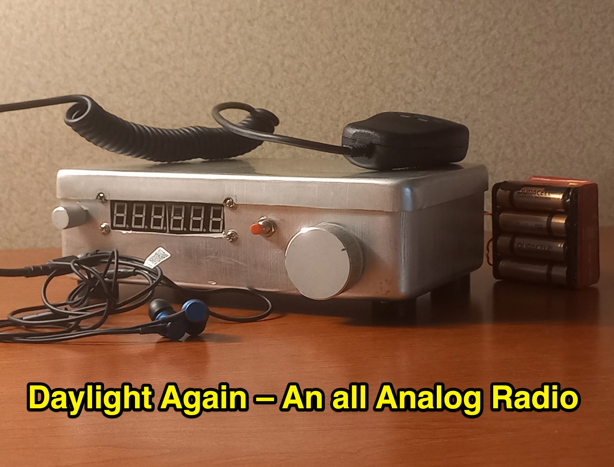 This article discusses a high performance, 7MHz, 5 watt SSB rig, the Daylight Radio, an all-analog radio design from the 1980s that includes a full circuit diagram, IMD NR60 calculations, QER crystal filter, bandpass filter, receiver portion, and more. The author explores the design, components, and functionality of this analog radio for hams interested in vintage or homebrew radio projects.
 -
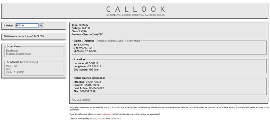 Callook provides a **USA amateur radio callsign lookup service** with data current as of March 25, 2026. The platform allows users to search for valid callsigns and retrieve detailed information, including geographic coordinates sourced from the Bing Maps API. A mathematically calculated **grid square** is derived from these coordinates, though accuracy is not guaranteed due to reliance on external services. The service supports multiple access methods, including a browser search plugin, direct API access with a reference, and plain text output for integration into other applications or scripts. This tool facilitates rapid identification of US amateur radio operators, offering an alternative to other callbook services. Its API access enables developers to integrate callsign lookup functionality into custom applications, streamlining data retrieval for logging software or contest management. The direct presentation of FCC data, combined with grid square calculation, assists DXers and contesters in verifying contact information and location details during on-air operations.
 -
 This page provides a calculator to determine the total line loss and additional line loss in your transmission line based on the level of SWR. It helps hams understand the impact of high SWR on transmission line losses. The calculator allows users to input their SWR level and get accurate calculations of total losses. This tool is useful for ham radio operators looking to optimize their transmission setups and improve overall efficiency.
 -
 This page provides a detailed example of the modeling and analysis of an 80m delta dipole antenna with a 600-ohm bifilar feedline. The model is based on antennas used by the RAF from 1940 to 1970. It covers the original model specifications, conductor mass calculations, resonance frequency observation, geometry adjustment steps, and final antenna dimensions. The content includes theoretical formulas, resonance frequency calculations, and practical steps for adjusting the antenna for optimal performance. Overall, it serves as a practical guide for hams looking to understand and optimize the performance of a delta dipole antenna for the 80m band.