Search results
Query: diagram
Links: 147 | Categories: 5
-
 The Quadlong antenna for the six meter band. This antenna feature a total gain of 6,4 dBd, F/B 21 dB and is also available in 70MHz version. Includes detailed pictures and plot diagrams.
 -
 A SSB CW transceiver for six meters band with schematic and block diagram
 -
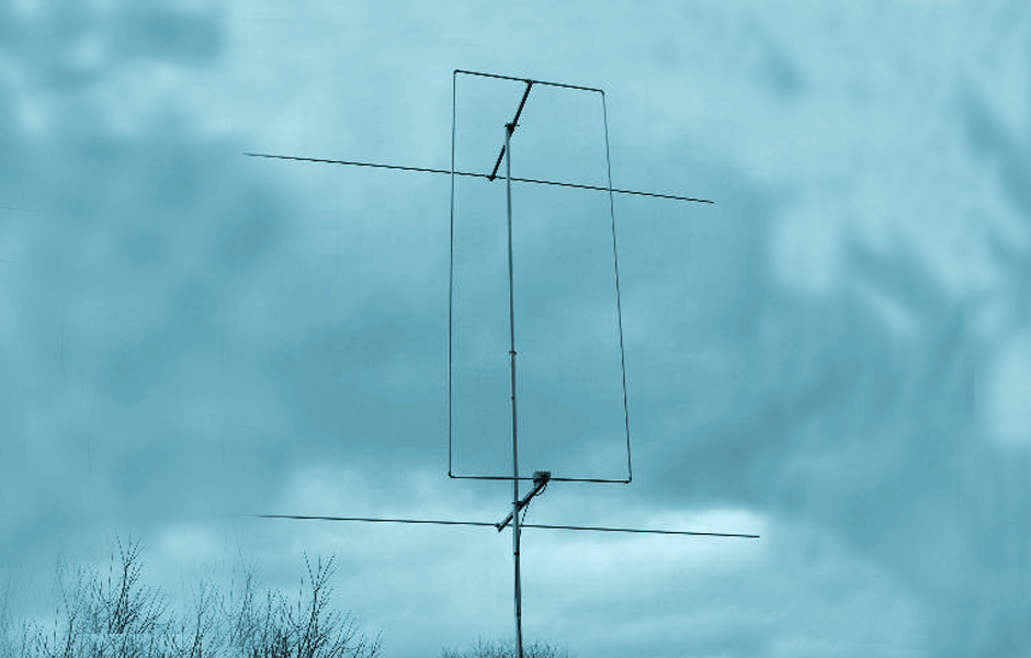
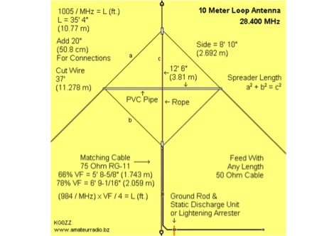 A nice loop antenna project for 28 MHz with schematic diagram, construction details and a complete video instruction
 -
 A 4 AMP / 18V regulated power supply schematic, designed by _ON6MU_, provides a detailed circuit diagram for constructing a robust power source. The design focuses on delivering a stable 18-volt output at up to 4 amperes, crucial for powering various amateur radio equipment. This resource presents a clear visual representation of component interconnections, including rectifiers, filter capacitors, and voltage regulation stages, essential for DIY enthusiasts building their shack infrastructure. The schematic's clarity facilitates understanding the power flow and component roles within the circuit. This circuit design offers a practical solution for hams needing a reliable 18V supply, potentially useful for driving specific transceivers, amplifiers, or accessory circuits. While specific performance measurements or comparisons to other designs are not detailed, the schematic itself serves as a foundational blueprint. Builders can adapt or modify the _power supply_ to suit their particular needs, such as integrating overcurrent protection or fine-tuning the output voltage with adjustable regulators. The straightforward presentation makes it accessible for those with basic electronics knowledge to assemble and troubleshoot.
 -
 One point eight MHz to 30 MHz is the operational bandwidth for this 4:1 Ruthroff voltage balun, designed to interface an unbalanced T-Match network with a balanced antenna system. The project details the construction using a _T200-2_ powdered iron toroid core, tightly wrapped in PVC electrical tape for insulation, and wound with 17 double bifilar turns of 1.25mm enamelled copper wire. This outboard balun offers flexibility, allowing hams to trial various baluns based on antenna system and impedance characteristics, rather than integrating it directly into the tuner. The resource includes a schematic of the balun, a wiring diagram showing winding connections, and a table suggesting alternative toroid cores like the T80-2 or T400-2 with corresponding winding counts. Component sourcing is straightforward, listing items such as the _Amidon_ T-200-2 core, SO-239 connector, and a sealed polycarbonate enclosure from Jaycar. Performance evaluation was conducted using an _AIM 4170C_ antenna analyser, demonstrating efficient 1:4 voltage transformation across the specified HF spectrum. Further efficiency tests involved measuring RF power loss at various frequencies, revealing minimal loss—less than 0.7 dB from 3.6 MHz to 30 MHz, and only 2.0 dB at 1.8 MHz. These measurements, performed under ideal 50-ohm conditions, confirm the balun's effectiveness as a low-loss interface for multi-band antenna systems. The page also links to several other balun and unun projects, including 1:1 current and voltage baluns, and 9:1 voltage ununs, providing a broader context for impedance matching solutions.
 -
 The resource presents a detailed schematic for constructing a dual-band vertical antenna, specifically designed for operation on the 2-meter and 70-centimeter amateur radio bands. It illustrates the physical layout, critical dimensions, and component placement necessary for successful replication. Key elements such as the radiating elements, phasing sections, and feed point are clearly depicted, providing a visual guide for radio amateurs undertaking a homebrew antenna project. The diagram specifies the lengths for the VHF and UHF sections, indicating how these elements are integrated to achieve dual-band functionality from a single coaxial feedline. It also implies the use of common materials readily available to most experimenters, focusing on simplicity and effectiveness in its design. The visual format of a GIF image ensures direct access to the construction details without requiring extensive textual interpretation. This schematic serves as a practical reference for hams interested in building a compact, efficient vertical antenna for local and regional FM communications, offering a proven design for immediate implementation.
 -

-
 Presents a QRP AM/CW transmitter project specifically designed for the 10-meter band, utilizing a crystal oscillator and a collector-modulated AM oscillator. The design employs a 2N2219(A) transistor in a Colpitts configuration, generating 100 to 350 mW of RF output power depending on the 9-18 Volt supply voltage and modulation depth. Frequency stability is maintained by a 28 MHz crystal, with fine-tuning possible via a Ct1 trimmer capacitor for approximately 1 kHz adjustment. The resource details the RF oscillator stage, implemented with a 2N2219 NPN transistor, emphasizing frequency stability and low power dissipation. It also covers the amplitude modulation stage, managed by a 2N2905 PNP transistor, which impresses audio information onto the carrier. Selective components (C3, C4, C7, C5) enhance voice frequencies within a +/- 5 kHz bandwidth, and modulation depth is controlled by R2 and R3. The project includes a 3-element L-type narrow bandpass filter (Ct3, L3, C10) to suppress harmonics and ensure a clean output signal. The project provides a complete schematic diagram, a comprehensive parts list including specific capacitor, resistor, and inductor values, and construction notes for the coils (L1, L2, L3). It also offers practical advice on enclosure requirements, suggesting an all-metal case or a PVC box with graphite paint for RF shielding. Operational parameters such as current draw (27mA@9V to 45mA@16V) and input impedance (50 Ohms) are specified, alongside guidance on antenna matching and the importance of a valid amateur radio license for 10-meter band operation.
 -
 This is a "techie" site, dedicated to presenting service manuals, parts lists, schematic diagrams and other information of value to restorers and technicians who try to keep these radios working
 -
 Color photos, schematic and diagrams for an article written by N2APB for Fall 2000 QRPp. Also the subject of a presentation made at the Pacificon QRP Forum in October 2000.An Integrated and Portable PSK Station for 80 & 20 without using a PC!
 -
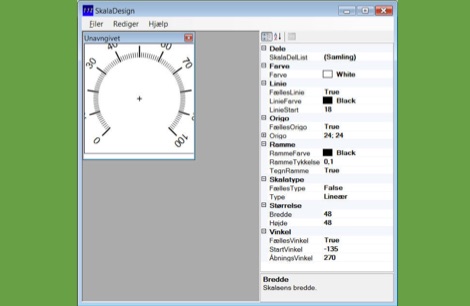 A danish only scale diagrams designer, usefull to draw front panels and dial scale knobs, windows freeware.
 -
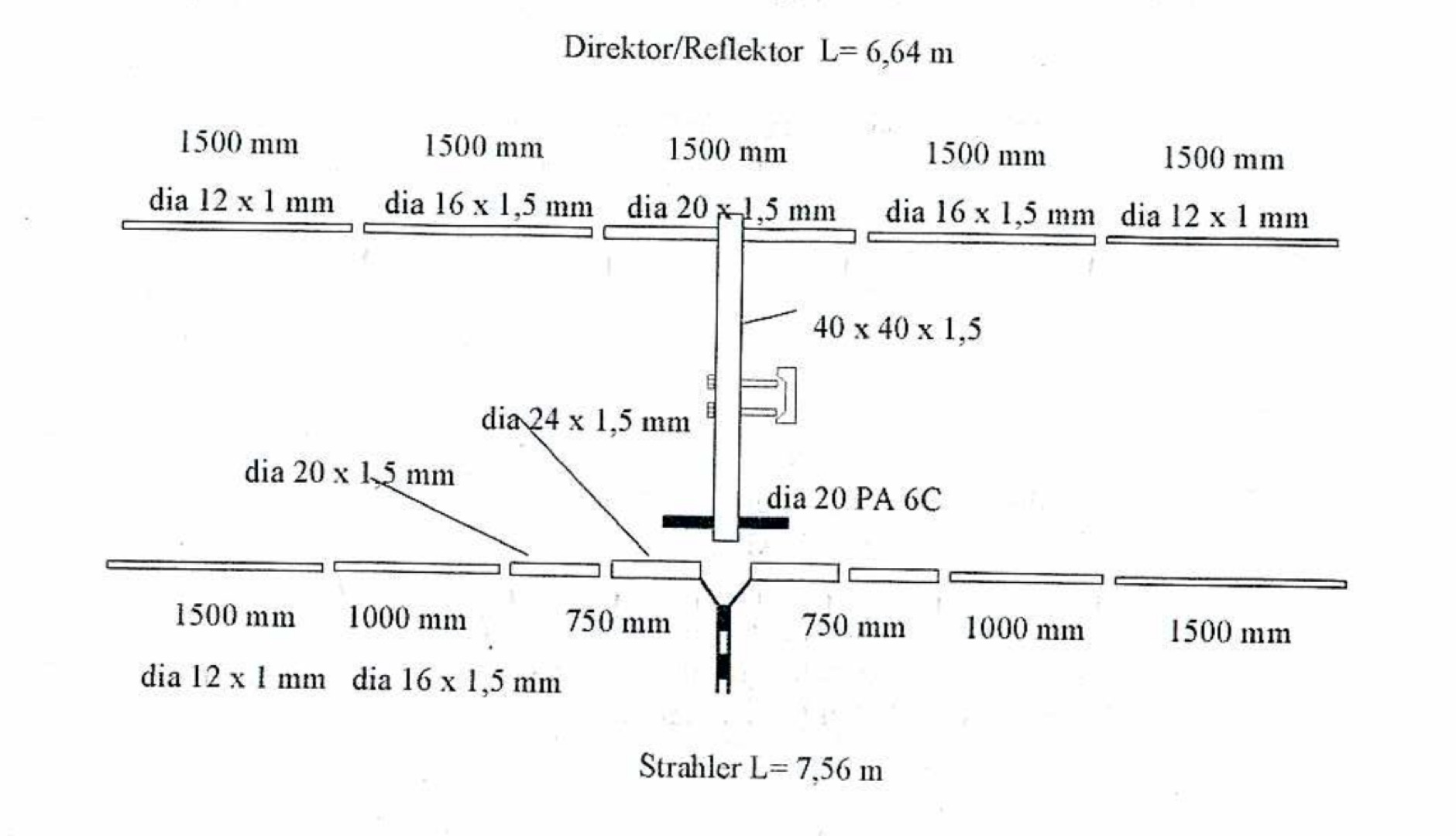
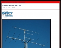 Antenna dimension, diagram and simulation of the ZX Antennen ZX 6-6 Yagi for VHF UHF by DF9CY
 -
 This document details the design and construction of the PA70H, a 50-watt RF amplifier for the 70MHz (4-meter) amateur radio band. Built around the Mitsubishi RD70HVF1 MOSFET transistor, the amplifier delivers 45-55W output with 3-5W input power while operating on 13.8V DC at approximately 7-8A. The PCB design incorporates multiple protection circuits including overcurrent, SWR, and temperature control. The amplifier features various control modes including GND PTT, +13.8V PTT, and RF VOX. Two versions are available: PA70HLI (requiring 100mW input with additional driver) and PA70H (for 3-5W input). The comprehensive documentation includes circuit diagrams, assembly instructions, and performance data showing successful operation from both 100mW and 3.5W input sources.
 -
 This PDF document details the construction of a **70 MHz** Big Wheel antenna, a horizontally polarized omnidirectional array. The design utilizes three full-wave loops, each approximately **2160 mm** in diameter, arranged in a triangular configuration. The resource provides mechanical dimensions for the antenna elements and a comprehensive bill of materials, specifying component quantities and types, such as M8 stainless steel bolts, 15x15x1.5 mm square aluminum tubing for spacers, and 8 mm aluminum rod for the arcs. The central hub is constructed from two 160x160x8 mm aluminum plates, with four 40 mm long polyamide insulators supporting the radiating elements. The feed system incorporates a 50 mm diameter aluminum pipe for mounting and a matching stub constructed from a 120x20x2 mm aluminum sheet, connected via M8x10 mm bolts. The resource includes a diagram illustrating the mechanical dimensions and assembly points, including the N-connector fixing point and the center conductor attachment. The project was published on May 25, 2011, by Peter OE5MPL and Rudi OE5VRL. DXZone Focus: PDF | 70 MHz Big Wheel | Mechanical Dimensions | **2160 mm** loop diameter
 -
 A PDF File of a Maria Maluca multiband HF antenna with schematic diagram, dimension and plan
 -
 Electro-Voice Model 664 (EV 664) cardioid microphone, wiring diagram, pictures and data sheet
 -
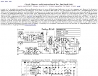 Circuit Diagram and Construction of the Bartling RX-40 Joachim Munch DF4ZS
 -
 Examines the historical role of telegraphy within Canadian railway operations, detailing the evolution of communication systems crucial for train dispatch and coordination. It covers the technical substance of railway telegraphy, including equipment, operational procedures, and the personnel involved, such as agents and operators. The resource provides insights into the **F59PH locomotive** history, development, and components, alongside diagrams of various parts like antennae and traction motors. The content also explores the practical application of these systems by documenting specific railway events, such as the CPR Galt Sub operations from 1895-1971 and GO Transit's operational history. It includes photo galleries, schematics, and diagrams of locomotives and cab cars, offering a visual and technical comparison of different railway equipment. The site also features information on **GO Transit** rolling stock, including MP40s and commuter coaches, providing a historical context for railway communication and transportation.
 -
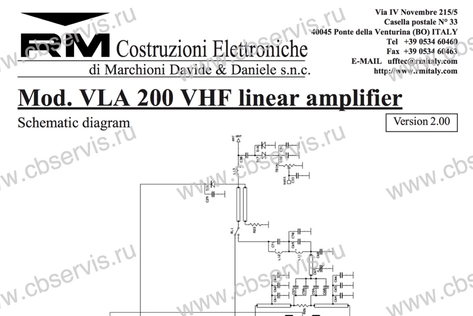 Schematic diagram of the VLA 200 power amplifier by RM Italy
 -
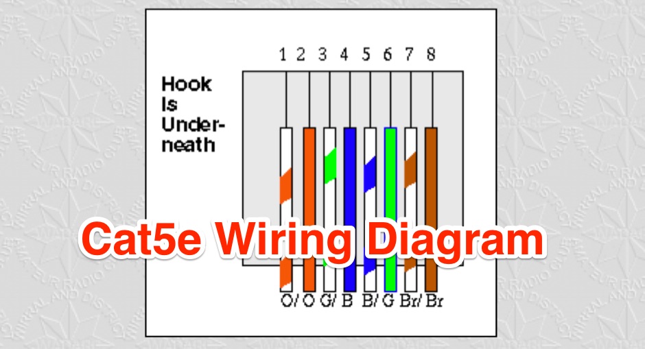 CAT5 T-568B Colour Code for RJ-45 Plug
 -
 Schematic diagram and description of a magnetic loop antenna that works from 10 to 20 meters band, made from junk
 -
 The resource details the construction of a multiband trap-style Inverted-V antenna designed for operation on 3.5 MHz, 7 MHz, 14 MHz, 21 MHz, and 28 MHz. It presents specific winding data for the traps, including the number of turns, wire gauge, and coil former dimensions, crucial for achieving resonance on the target bands. The document provides a parts list and a diagram illustrating the antenna's physical layout and trap placement. It outlines the process for building the traps using PVC pipe formers and specifies the required capacitor values for each trap. The design emphasizes a practical approach to achieving multiband operation with a single feedline, a common goal for HF operators with limited space. The document includes a table with antenna segment lengths for each band, allowing for precise replication of the design. It also offers insights into tuning and adjustment, ensuring the antenna performs optimally across the designated amateur radio bands.
 -
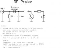
 A home made field strength meter wit detailed pictures and schematic diagram by W4ZT
 -
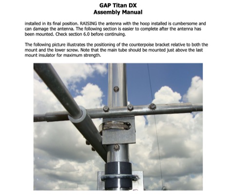 This manual is an edited version of the GAP supplied document, complete with diagrams, pictures and assembling notes by Mitch Baum AE2A. This is 29 pages document in PDF Format.
 -
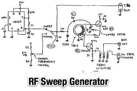 A simple RF sweep generator circuit diagram by JF1OZL
 -
 Collection of several Crystal Radio receiver circuits with schematics diagrams and pictures
 -
 The page provides detailed instructions on how to build a 60 meter End Fed Half Wave Antenna Tuner, with large pictures and diagrams. It is aimed at amateur radio operators looking to construct their own antennas for the 60 meter band.
 -
 Kenwood schematics diagrams in high resolution format, includes Kenwood TS-830S , TS-820S and TS-520S
 -
 This online project guide details the construction of a homebrew boom microphone system. It details the assembly of a microphone shell from a 3/4" PVC pipe section and an end cap, requiring a drilled hole for a snug fit of the electret or condenser mic element. The internal wiring schematic specifies a **2.2 K** resistor and a **47 uF** polar capacitor for signal conditioning, with a circuit diagram provided for integration with IC-706 series transceivers. The guide outlines the use of CAT-5 cable for internal connections, incorporating strain relief at the rear of the mic shell, and an inline 3.5 mm jack to facilitate an external _PTT_ line, designed for a foot-mounted switch. Further construction involves fabricating a microphone shock mount from a 2-inch PVC connector, detailing the creation of four "fingers" and the insertion of screw-eyes for attaching elastic bands, which are twisted 180 degrees for tensioning and vibration isolation. A foam wind screen is also incorporated into the microphone assembly, secured with adhesive. The boom arm itself is repurposed from an articulated architect lamp, with the original lamp assembly converted into a **60 watt** resistive load for testing power sources. Microphone cabling is secured to the boom arm using wire ties, ensuring sufficient slack at hinge points to maintain articulation. The boom base is mounted to a bookshelf, requiring specific positioning to achieve proper microphone placement in front of the operator. Performance evaluation of the microphone system is conducted through on-air audio signal reports from other amateur radio operators. DXZone Focus: Online Project Guide | Boom Microphone Construction | Electret Mic Element | PTT Line
 -
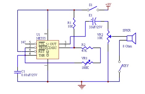 This code practice oscillator project uses a 555 timer IC. Includes a Schematic Diagram of the morse code oscillator
 -
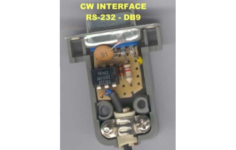 A RS-232 to DB9 CW Radio interface with schematic diagram to connect your pc running CT by K1EA or Writelog to your keyer.
 -
 Christoph Petermann DF9CY DRM demonstration receiver project including Circuit Diagram and component list
 -
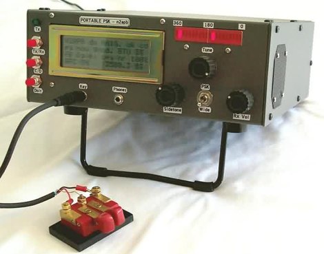 Integrated PSK station for 80 & 20 meters without using a PC Pictures and diagrams by N2APB
 -
 An introduction to RF mixes and their main characteristics, article with diagrams and illustrations by VA3IUL
 -
 The WB5RVZ Genesis Radio G40 build log documents the construction of a 5W QRP 40m SDR transceiver kit, detailing each phase of assembly from power supply to RF filtering. It provides specific component lists, parts placement diagrams, and testing procedures for stages like the local oscillator, Tayloe detector, and RX op-amps. The resource highlights discrepancies between documentation versions and offers practical advice for builders, including a "virtual build" approach to preemptively address potential ambiguities in component identification and placement. It also addresses a specific "VK6IC Fix" for early board revisions, involving trace cuts and jumper wires for improved performance. The build log presents measured voltages and expected current consumption for various stages, such as the 4.9-5.0 Vdc on the 5V rail and under 100mA for RX current. It outlines critical adjustments like image rejection tuning, a common procedure for direct conversion receivers. The resource also includes practical tips for handling components like the 2N3866 transistor and its heatsink, emphasizing pre-assembly. It details the winding of two 1.45 uH toroidal inductors on T50-6 cores with 17 turns of #20 AWG wire, crucial for the RF path.
 -
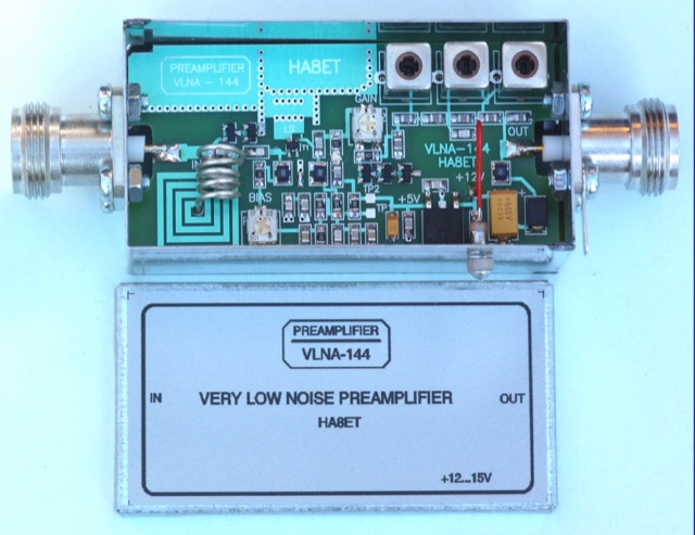 An home made low noise preamplifier project for 144 MHz, with detailed circuit diagram. The VLNA-144 preamplifier has been Published on DUBUS 4 2019
 -
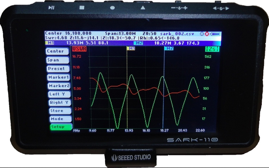 The SARK-110 is a completely new design concept for an Antenna Analyzer. This is a truly pocket size device, so you can take it anywhere. It offers a gorgeous 3" high-resolution, active-matrix color display that allows information-rich diagrams, works from 0.1 to 230MHz
 -
 A NiCAD Battery Charger with Current and Voltage Limiting
 -
-
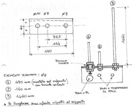 A multiband J-Pole antenna project that cover 144,220 and 430 MHz. The articles includes several pictures of this multi-band antenna, including handmade schematics and diagrams, project is mainly in Italian
 -
 Schematic diagram for a high voltage power supply by W4NFR
 -
 In this article the author shows the receiving loop antenna for 160 meters band installed at his QTH. Diagram and movie available. Article in in Turkish but can be translated in english
 -
 DTMF Keypad for radios without one. A project with picture and schematic diagrams to homemade a DTMF keppad
 -
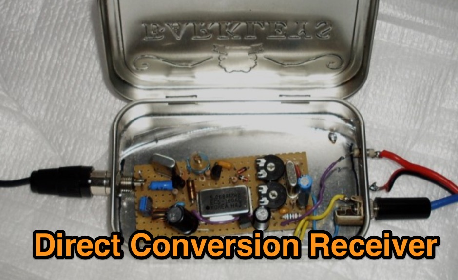 A schematic diagram of a homemade direct conversion receiver for 30 meters band
 -
 Presents the full owner's manual for the _Drake R-4C_ communications receiver, specifically a late version edition. This resource outlines the comprehensive operational instructions, covering everything from initial setup and tuning to advanced features and controls. Hams can reference detailed diagrams and explanations for proper signal reception across various amateur bands. The manual includes critical information for alignment procedures, ensuring the receiver performs to its optimal specifications. It details the steps required for calibrating the internal circuitry, which is essential for maintaining sensitivity and selectivity over time. My experience with vintage Drake gear confirms the value of these original documents for accurate adjustments. Furthermore, the document provides insights into troubleshooting common issues and performing routine maintenance. It serves as an authoritative guide for anyone operating or servicing this classic piece of amateur radio equipment, helping to preserve its functionality for years of DXing and ragchewing.
 -
 This DIY vertical multi-band Windom antenna offers a practical and effective solution for amateur radio enthusiasts seeking a versatile and compact antenna for HF communications. Its simplicity of construction, multi-band capability, and favorable performance make it a valuable addition to any radio shack. The article provides detailed instructions on constructing the antenna and balun, along with diagrams and component specifications. Field tests demonstrated successful contacts with stations across Europe and North America on 14, 18, and 28 MHz. The antenna exhibited comparable performance to a W3DZZ dipole and outperformed a Cobweb antenna on 18 MHz. Low noise levels were observed, effectively suppressing background noise.
 -
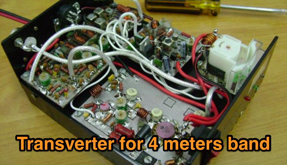 A 70 MHz Transverter project with a block diagram and schematics
 -
 Schematic diagram of a two tone audio oscillator by VK3YE
 -
 This battery charger circuit is regulated and adjustable to make this circuit able to charge the mosto NiCAD battery.
 -
 Station QRP presents various **circuit diagrams** for constructing low-power AM vacuum tube shortwave transmitters, catering to enthusiasts interested in vintage radio technology. The resource details schematics ranging from simple to more complex designs, enabling hams to build their own QRP AM transmitters for operation on frequencies like 6.925 kHz AM. It emphasizes the use of vacuum tubes, providing a technical foundation for understanding and replicating classic shortwave broadcasting methods. The content is geared towards those who enjoy the hands-on aspect of electronics and the unique characteristics of tube-based RF circuits. Building these transmitters allows operators to experience the nostalgia of early shortwave radio, with the site specifically mentioning a pioneer station on 6.925 kHz AM. The designs facilitate experimentation with low-power AM transmission, offering practical application for homebrew projects. The focus on QRP (low power) operation aligns with a segment of the amateur radio community that values efficiency and minimalist setups, providing a distinct alternative to modern solid-state transceivers.