Search results
Query: front
Links: 106 | Categories: 3
-
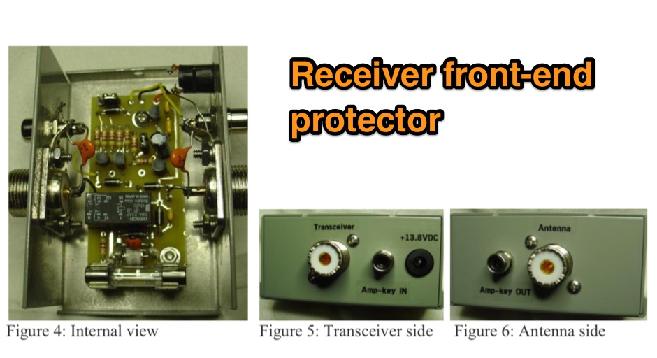 A transceiver front-end protector in high signal level environments. An homemade RF limiter to protect your receiver front-end from high radio frequency.
 -
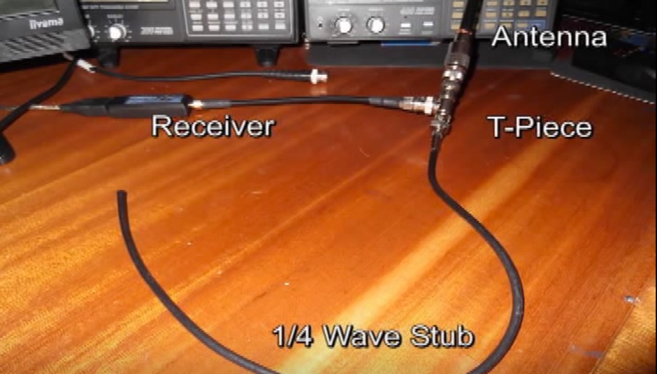 Cutting out the noise using a simple coax filter to improve the poor front end filtering
 -
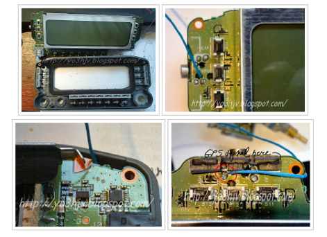 A custom modification RC-D710 GPS-INSIDE mod.
 -
 Optimizing weak signal reception on the HF bands, particularly in the presence of strong local QRM, often necessitates specialized receiving antenna systems. This resource details the _HI-Z Antennas_ product line, focusing on phased vertical arrays designed for superior noise rejection and directivity. It covers components such as the 4-Square and 8-Element array controllers, which allow for rapid switching of receive patterns, and dedicated low-noise preamplifiers to improve system sensitivity. The site also presents various bandpass filters, crucial for mitigating out-of-band interference and enhancing the dynamic range of the receiver. The HI-Z systems are engineered to provide significant front-to-back and side rejection, often yielding **20-30 dB** of attenuation to unwanted signals, which is critical for DXing and contesting. Users can achieve a notable reduction in local noise, allowing for the discernment of signals that would otherwise be buried. The array controllers facilitate quick pattern changes, enabling operators to null out interference or peak weak signals from distant stations, effectively extending the reach of their receive capabilities by improving the signal-to-noise ratio.
 -
 Getting squeaks and squawks from your H-T? Are pagers crunching your mobile rig's front end? Here's how intermod happens--and how to fight back!
 -
 The _Sci.Electronics FAQ: Repair: RFI/EMI Info_ document, authored by Daniel 9V1ZV, provides a detailed analysis of computer-generated RFI/EMI, focusing on its impact on radio reception. It identifies common RFI sources such as CPU clock rates (e.g., 4.77 MHz to 80 MHz), video card oscillators (e.g., 14.316 MHz), and even keyboard microprocessors, all of which generate square-wave harmonics across HF and L-VHF regions. The resource outlines a systematic procedure for pinpointing RFI origins, including disconnecting peripherals and using a portable AM/SW receiver with a ferrite rod antenna to localize strong interference sources. The document categorizes RFI mitigation into shielding, filtering, and design problems, offering practical solutions for each. It recommends applying conductive sprays like _EMI-LAC_ or _EMV-LACK_ to plastic casings of radios, monitors, and CPUs to create effective Faraday cages, emphasizing proper grounding and avoiding short circuits. For filtering, the guide suggests using line filters, ferrite beads, and toroids on power and data lines, and small value capacitors (e.g., 0.01 uF for serial/parallel, 100 pF for video) to shunt RFI to ground. It also discusses the use of bandpass, high-pass, low-pass, and notch filters on the receiver front-end or antenna feed to combat specific in-band noise.
 -
 This online project guide details the construction of a homebrew boom microphone system. It details the assembly of a microphone shell from a 3/4" PVC pipe section and an end cap, requiring a drilled hole for a snug fit of the electret or condenser mic element. The internal wiring schematic specifies a **2.2 K** resistor and a **47 uF** polar capacitor for signal conditioning, with a circuit diagram provided for integration with IC-706 series transceivers. The guide outlines the use of CAT-5 cable for internal connections, incorporating strain relief at the rear of the mic shell, and an inline 3.5 mm jack to facilitate an external _PTT_ line, designed for a foot-mounted switch. Further construction involves fabricating a microphone shock mount from a 2-inch PVC connector, detailing the creation of four "fingers" and the insertion of screw-eyes for attaching elastic bands, which are twisted 180 degrees for tensioning and vibration isolation. A foam wind screen is also incorporated into the microphone assembly, secured with adhesive. The boom arm itself is repurposed from an articulated architect lamp, with the original lamp assembly converted into a **60 watt** resistive load for testing power sources. Microphone cabling is secured to the boom arm using wire ties, ensuring sufficient slack at hinge points to maintain articulation. The boom base is mounted to a bookshelf, requiring specific positioning to achieve proper microphone placement in front of the operator. Performance evaluation of the microphone system is conducted through on-air audio signal reports from other amateur radio operators. DXZone Focus: Online Project Guide | Boom Microphone Construction | Electret Mic Element | PTT Line
 -
 Arizona near space research - promoting science and education by exploring frontiers in amateur radio and high altitude balloons.
 -
 Constructing a compact directional antenna for the 17-meter band, this resource details the build process for a Moxon rectangle, a two-element Yagi variant with folded-back elements. It covers the antenna's evolution from the _VK2ABQ beam_ and provides specific dimensions for a version built using fishing pole whips. The content includes a discussion of the antenna's radiation pattern, feedpoint impedance, and its inherent front-to-back ratio, which is often superior to a standard two-element Yagi. Practical considerations for element spacing and material choices are also addressed, alongside a visual representation of the antenna's physical layout. Performance data presented includes a comparison showing the Moxon rectangle's **2.5 dB gain** over a half-wave dipole and a front-to-back ratio of **20 dB**. The resource also touches upon the antenna's relatively wide bandwidth for a two-element beam and its suitability for portable operations due to its compact footprint. It offers insights into optimizing the design for specific operating conditions and discusses the advantages of its lower take-off angle compared to omnidirectional wire antennas, making it effective for DX contacts on the 17-meter band.
 -
 Moxon is a rectangle shaped directional antenna, originally designed by Les Moxon G6XN. There are couple of advantages of using this antenna. It is small in size, Easy to mast, Balanced to 50 Ohms, Near 1:1 SWR, Excellent Front to Back (F/B) ratio, Large bandwidth
 -
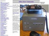 A small (FT-817) I.F. radio driving a 100w transverter with a 1db nf front end.
 -
 The **Escort** series Tactical Carrying System provides robust protection and enhanced portability for popular HF transceivers, addressing the need for secure field operation and transport. These systems, designed for models such as the Yaesu FT-857D/891, FT-991, FT-817/818ND, and Icom IC-706/703/7000, IC-7300, feature military-grade construction with front panel protection and versatile carrying strap attachment points. Operators can confidently deploy their rigs in various environments, from SOTA activations to casual field days, knowing their equipment is safeguarded against bumps and impacts. Beyond tactical carriers, Portable Zero LLC also produces the **Sherpa Pack** for the Yaesu FT-817 and the Field Power 12 and Field Power 3 Battery Cases. These accessories complement portable operations by providing essential power solutions and additional carrying options, facilitating extended off-grid activity. Established no later than 2013, Portable Zero LLC manufactures its products in the USA, leveraging CAD design and CNC precision laser cutting for consistent quality. The company's commitment to enhancing portable amateur radio operations is evident in its specialized product line, available in finishes like Black Texture and OD Green.
 -
 CRAM - Club Centro Radioaficionados Montevideo, CX1CCC, Montevideo, Uruguay
 -
 A cavity filter, often a critical component in _duplexer_ designs, functions as a sharply tuned resonant circuit, allowing only specific frequencies to pass while attenuating others. These filters are essential for maintaining signal integrity in environments where multiple transmitters and receivers operate simultaneously on closely spaced frequencies, such as in repeater stations. The article details how these filters, sometimes referred to as _notch filters_, achieve high Q factors, which are crucial for their performance. Understanding the principles of cavity filters is fundamental for any amateur radio operator involved in repeater operation or designing custom RF front-ends. The discussion covers the basic circuitry and operational characteristics that enable these devices to provide significant isolation, often achieving **-80 dB** or more between transmit and receive paths. This level of isolation is vital for preventing receiver desensitization and intermodulation distortion. Properly tuned cavity filters ensure that a repeater can transmit and receive simultaneously on different frequencies without self-interference, a common challenge in VHF/UHF operations.
 -

-
 Elk Antennas to give the Ham log periodic antennas with the best gain, directivity, and front to back ratio possible for the size and price.
 -
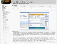 KComm, a logging and communication program, was specifically engineered for Elecraft K2, K3, and KX3 transceivers, leveraging the Lazarus cross-platform development tool. It operates natively on Windows XP and can be compiled for Linux, with potential for macOS, prioritizing low resource usage for casual DXers and contest participants. The software integrates with external applications like Fldigi for diverse digital modes and CW Skimmer for advanced Morse decoding, enhancing its functionality beyond basic logging. The design philosophy of KComm emphasizes utilizing the physical radio controls for operational adjustments, rather than replacing the transceiver's front panel. It facilitates keyboard CW operation via the Elecraft serial protocol and capitalizes on the K3 and KX3's built-in decoders for RTTY and PSK31. Additionally, KComm supports PSK31, PSK63, and PSK125 through the AE4JY PSK Core DLL on Windows and integrates with PSKReporter.info for spotting. While not a dedicated contest logging or award tracking program, KComm supports ADIF and Cabrillo export for casual use, allowing logs to be imported into other software. The author, G4ILO, ceased all software development, providing KComm "as is" without further support or updates; however, the source code is available under the GNU GPL for community continuation.
 -
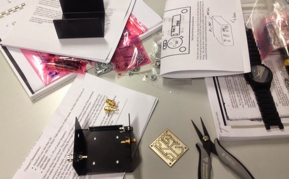
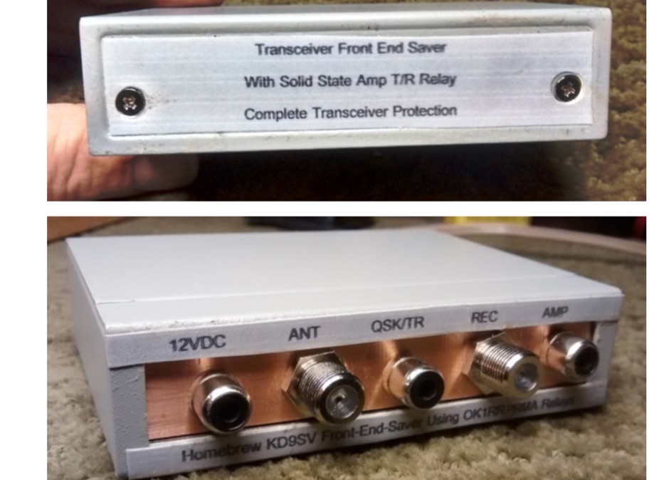 Homemade RF limiter project, to protect the K3 receiver front-end for high radiofrequency based on the original KD9SV project.
 -
 The simple and convenient way to a custom front panel - even for single units. Custom-designed front panels and enclosures for electronic equipment.
 -
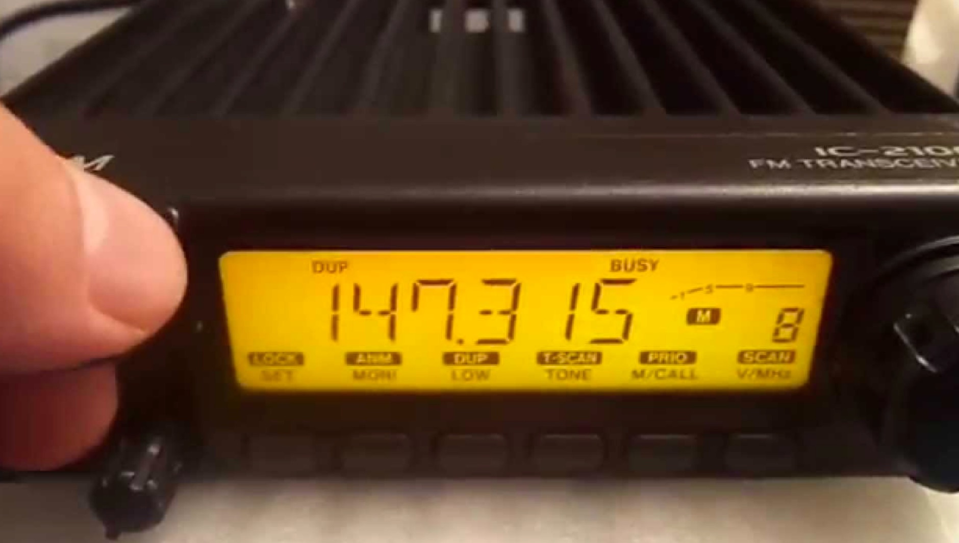 Six Steps for Programming your IC-2100H from the front panel of radio. Using these steps you should have no trouble entering either simplex or repeater frequencies and saving them.
 -
 It is very compact, low noise and directive with an impressive 20 to 25 dB front to back
 -
 A 0-30 MHz step attenuator, constructed from switchable Pi attenuation pads, provides a practical tool for evaluating receiver sensitivity and calibrating S-meters. The design utilizes readily available 5% tolerance resistors, with values derived from paralleled components to achieve specific attenuation steps. A schematic (Fig 1) illustrates the circuit, including PCB pad shielding, while a table details required and actual resistor values, along with percentage differences. Measurements of voltage input versus output at various frequencies are used to calculate dB attenuation, presented in a graph (Fig 4). The resource includes formulas for determining output voltage from a known input and a comprehensive 0-40 dB voltage multiplier table, which is crucial for precise signal level management. The project also references external attenuator calculators and equations for further study. Photos (1-3) provide visual guidance for the assembled unit, showing bottom, top, and front views. The project emphasizes the use of **Pi attenuation pads** and **receiver sensitivity** evaluation, offering a hands-on approach to RF signal management.
 -
 RF is causing strange issues on the touch sensor buttons, controlling inputs, volume, channels on Samsung LCD TV. Solution is to disable front touch panel.
 -
 Delivering confidence to confront the most challenging microwave and RF designs. Spectrum Analyzers by Tektronix
 -
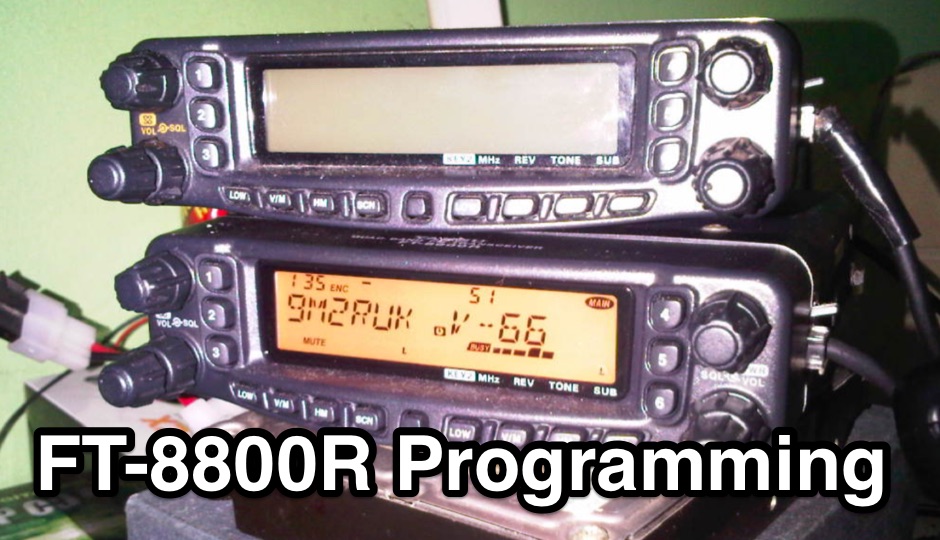 Programming the FT-8800R via the front panel and microphone keypad is not extremely difficult. Already having a list of local repeaters in CHIRP, the addition of a USB cable would allow you to coordinate the memory layout across multiple radios with ease.
 -
 AN-SOF is a professional comprehensive software tool for the modeling and simulation of antenna systems. AS-SOF allows to describe antenna geometry, Choose construction materials, Describe the environment and ground conditions, Describe the antenna height above ground, Analize radiation pattern and front-to-back ratio, Plot directivity and gain, Analize input impedance and VSWR,Predict antenna bandwidth
 -
 This article presents an innovative homebrew antenna design utilizing surplus ladder line as a receiving antenna for HF and MF bands. The Ladder Line Antenna (LLA) transforms standard 450-ohm ladder line into a directional, bidirectional, or omnidirectional antenna system through different termination methods. The design, which requires minimal space and height, achieves 6-10dB front-to-back ratio on 40-160m bands using a 33-foot length. This DIY wire antenna project offers an efficient, low-profile solution for amateur radio operators, featuring broadband operation without ground radials and easy installation below fence height.
 -
 Liberia 2011 5M2TT DX Pedition Official web site
 -
 Operating in a Single Operator Two Radios (SO2R) setup, especially with beverage antennas, often exposes the receiving radio's front-end to significant RF energy from the transmitting radio. This resource details a practical, homebrew receiver protection circuit designed to mitigate this risk. The core of the design involves a non-inductive 2W 22 Ohm carbon composition resistor in series with the RX antenna line, followed by two stacks of four fast-switching diodes (e.g., _1N914_) configured in opposite polarizations. This arrangement effectively clamps the incoming voltage to approximately 2.8 V peak-to-peak, safeguarding sensitive receiver input components. The series resistor plays a crucial role by absorbing excess power, preventing the diodes from exceeding their current ratings and potentially failing open, which would leave the receiver unprotected. The author, _N4KG_, measured up to 50 watts of coupled power between 80M slopers on the same tower, highlighting the necessity of such protection. The design is presented as a cost-effective solution to prevent damage to receiver input transformers, with the author noting successful protection of a receiver even after a resistor showed signs of overheating. This simple circuit can be integrated via a transverter plug, offering a robust defense against high RF input.
 -
 If You are using a separate receive antennas then you need a good protection circuit to eliminate the possibility of blowing out the receiver front-end while using these auxiliary receive antennas specially on low bands.
 -
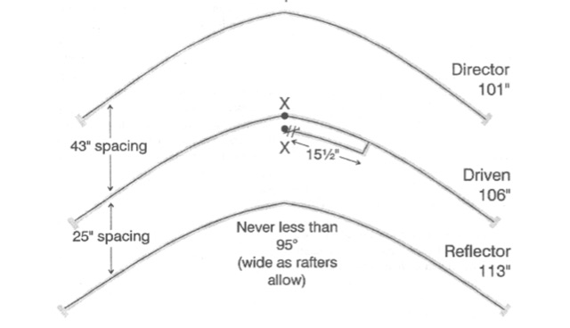
 In this article, Steve G0UIH presents a straightforward guide for constructing a lightweight 15m 3 Element Yagi antenna with impressive performance metrics. With a focus on ease of construction and efficiency, the design boasts a nearly 8.2dbi forward gain and 30db front to back ratio. Utilizing readily available materials and a hairpin match for impedance matching, this Yagi offers broad bandwidth and simple tuning for optimal operation across the 15m band.
 -
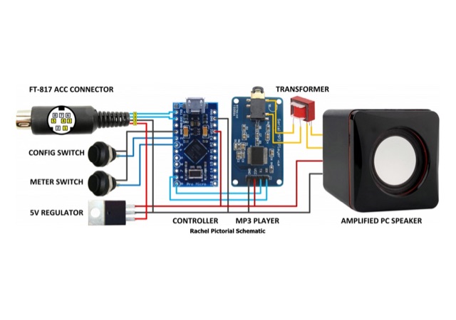 This construction project is for anyone wanting to give this popular little radio a voice of its own. This Speech synthesiser reads out the current frequency, mode and menu settings whenever they are changed via the front-panel controls
 -
 The HB9CV antenna calculator aids amateur radio enthusiasts in designing antennas for VHF and UHF bands. By inputting the working frequency, users can obtain crucial dimensions like dipole lengths and distances. The tool, based on the HFSS antenna model, provides data on impedance, VSWR, and gain, optimizing front/back radiation ratios. It includes tips for fine-tuning using a Г-matching balun and compensating capacitor, ensuring effective performance and minimal VSWR for enhanced radio communications and direction finding.
 -
 This project involves constructing a dual-band Moxon antenna, optimized for ham radio enthusiasts, with functionality on both the 10-meter and 6-meter bands. The antenna is designed to operate using a single 50-ohm feedpoint, acting as a mini-beam on 28 MHz (10 meters) and as a 2-element Yagi on 50 MHz (6 meters). Performance-wise, it offers a 4.0 dBd gain on 10 meters and 4.3 dBd on 6 meters, with impressive front-to-back ratios of 30 dB and 11 dB, respectively. Builders like Aleks (S54S) and Marcio (PY2OK) have successfully brought this design to life using the provided specifications. Aleks noted that bending the corners of the structure proved especially useful during assembly. The project comes with a detailed parts list, highlighting the use of aluminum tubes with different diameters and lengths to form essential components like the reflectors and radiators. For those looking to fine-tune the antenna, adjustments can be made by altering the length of certain parts that fit into larger tubes. The feeding system is equipped with a balun to accommodate different power levels, making the design versatile enough to handle outputs of either 300 watts or 1 kilowatt.
 -
 This design makes the most of having to put an aerial in the attic. This inverted-vee yagi is giving good results at GW0GHF. Directive gain is about 6 dBd. The front-to-back ratio is not brilliant, about 20 dBd.
 -
 Online antenna calculator for a basic 3 elements yagi uda directional antenna. The described antenna design offers a front-to-back ratio of at least 20 dB, a gain exceeding 7.3 dBi, and a bandwidth (SWR < 2) of approximately 7% around the center frequency. It has an input impedance of 50 ohms when using a straight split dipole, which can be substituted with a folded dipole of the same length, increasing the impedance to 200 ohms. A matching balun is required for coaxial feeder connection, and the boom should be made of a dielectric material, like wood.
 -
 This project introduces the Loggi, a hybrid antenna merging the wide frequency coverage of log-periodic dipole arrays (LPDA) with the high gain and front-to-back ratio (F/B) of Yagi antennas. Traditional LPDAs span broad frequencies with moderate gain and low VSWR, while Yagis provide high gain and F/B over narrow bands. By analyzing high-Tau LPDA designs, it was found they could nearly match the gain of VHF/UHF Yagis while maintaining excellent patterns, F/B, and front-to-rear ratios (F/R). Optimizing specific elements for target frequencies (e.g., 144.1 MHz) led to the Loggi, which uniquely features all driven elements without passive directors or reflectors. This design effectively functions as a narrowband optimized LPDA, with front elements acting like Yagi directors and rear elements like Yagi reflectors, thus enhancing gain and directional characteristics while retaining broad frequency versatility.
 -
 This page provides information on designing a lightweight Moxon antenna for the upper HF bands and VHF. The Moxon antenna is a compact version of a 2-element Yagi with folded elements, offering good forward gain and a high front-to-back ratio. It is designed for a single band with a feed-point impedance close to 50 ohms. Hams can orient the antenna horizontally or vertically, with polarization following the configuration, affecting radiation patterns. The page allows users to generate radiation pattern plots, VSWR charts, antenna currents diagrams, and Smith charts for their antennas on different ground types, helping them understand antenna performance in the field.
 -
 The article describes a high-gain, compact beam antenna design for the 2-meter band (144-146 MHz). The NSH 4x4 Boomer is a 4-element antenna that is mounted on a 4-foot boom with an 8.2 dB gain, 1.2:1 SWR, and a front-to-back ratio of 18 db. It is designed for mobile operations and little area, making it perfect for field usage such as disaster management. The design employs regularly spaced parts with a straightforward gamma match for tuning, and the construction materials include a square boom and polished aluminum tubes. In local and portable tests, the antenna worked regularly, achieving contact distances of up to 15 kilometers.
 -
 This page provides construction details for a 4-element 10-meter Yagi antenna with 28 Ohm impedance. It includes information on the elements, positions, diagrams, and data related to frequency, gain, front-to-rear ratio, radiation resistance, SWR, and loss. The content is aimed at hams or radio operators interested in building and optimizing Yagi antennas for the 10-meter band.
 -
 The author describes his experience building and using a Beverage antenna for the 40-meter band. Despite encountering some challenges, the antenna offered some improvements in receiving stations compared to a 3-element inverted Vee antenna. The Beverage antenna showed a significant daytime signal-to-noise ratio improvement and received signals better than the Vee antenna. However, the front-to-back ratio was not ideal, and the transmit power seemed to affect the Beverage antenna. Overall, the author concludes that the Beverage antenna might be more suitable for locations with higher noise levels. The total cost of the antenna was around 30 Euros.
 -
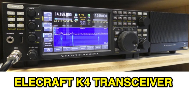 Collection of test reports done by Rob Sherwood on the Elecraft K4D, this version of the K4 does not have the hybrid front-end.
 -
 This is a plan for an optimized element UHF Yagi Antenna for UHF Bands featuring a 9dBd forward gain, a 13 dB front-back ratio, and a bandwith of 10 MHz on the 430-440MHz range.
 -
 This article explores the nuanced design challenges of Band Pass Filters (BPF) in radio receivers, balancing low insertion loss, high stop band rejection, and narrow bandwidth. The focus is on the "Series-Trap, Shunt-C" topology, resonator count impact, and meticulous layout design for superior stop band performance across various frequency bands
 -
 A cost-effective alternative to the Optibeam OB10-3W, a high-performance but expensive tri-band Yagi antenna for the 20, 17, and 15-meter bands. The original Optibeam, featuring three full-size elements on each band, delivers strong forward gain and front-to-back ratio but comes with a high price tag. To address this, a custom design was developed, offering similar performance at a fraction of the cost. Using accessible materials and a simple 1:1 current balun, the homemade version proved highly effective, making it a practical solution.
 -
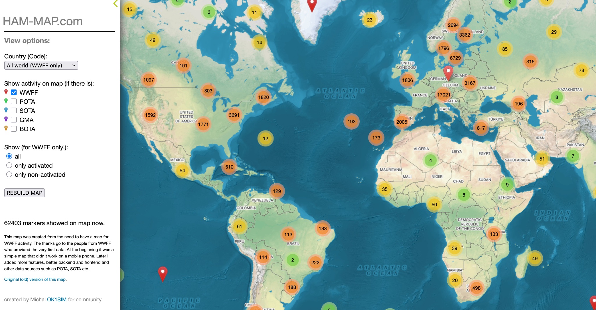 This map was created from the need to have a map for WWFF activity. The thanks go to the people from WWFF who provided the very first data. At the beginning it was a simple map that didn't work on a mobile phone. Later I added more features, better backend and frontend and other data sources such as POTA, SOTA etc.
 -
 The article discusses the evolution of antenna designs, specifically focusing on the upgrade from the W7IUV rotatable Flag to the Waller Flag. Author Pierluigi Mansutti IV3PRK shares insights on modeling these antennas using EZNEC software, detailing their performance in noisy environments. The W7IUV Flag proved effective for receiving signals, while the Waller Flag, developed by NX4D and N4IS, offers improved front-to-back ratios but requires careful consideration of signal levels and noise management. The article emphasizes practical modeling results and interactions between different antenna setups.
 -
 This project involved designing a 7-pole Chebychev broadcast band filter to address severe interference issues caused by a new horizontal loop antenna on the KN-Q7A transceiver. The interference overwhelmed the transceiver’s front end, so a custom filter with a 3.5 MHz cutoff was built using silver mica capacitors and type 6 T130 toroidal cores. Encased in a diecast box with SO239 sockets, the filter blocks strong signals from the broadcast band, achieving over 100 dB attenuation. Tested up to 100W, it reduces interference effectively while maintaining low insertion loss across HF bands.
 -
 Facilitate seamless communication in the world of packet radio with PoPT, a versatile terminal program designed for AX.25 protocol enthusiasts. Operating across multiple platforms, including Windows, Linux, macOS, and Raspberry Pi, it caters to a wide range of users. The program supports various connection methods such as KISS over TCP/Serial and AXIP over UDP, ensuring compatibility with Linux AX.25 devices. This flexibility allows operators to maintain robust connections in diverse environments. Developed with Python 3.11, PoPT is currently under active development, reflecting a commitment to staying at the forefront of technological advancements. Its multi-platform nature ensures that operators can leverage their existing hardware setups without the need for additional investments. The program's ability to handle different connection types makes it a valuable tool for those engaged in packet radio operations, whether for personal experimentation or more structured communication networks. PoPT's ongoing development promises future enhancements and features, making it a dynamic choice for operators looking to explore the capabilities of AX.25 packet radio. Its adaptability and support for modern systems position it as a practical solution for contemporary amateur radio enthusiasts.