Search results
Query: height of antenna
Links: 81 | Categories: 0
-
 This wire antenna for 40 and 20 meter band feature a good SWR. Horizontal side of the antenna is placed at two meters above the ground. Impedance of the antenna are depending by the height of the base from the ground and conditions of the ground
 -
 This web article details the construction of a 4-meter band coaxial dipole antenna, designed for operation between **70.000 MHz and 70.500 MHz**. The resource provides a bill of materials and step-by-step assembly instructions for a half-wave dipole constructed from _RG-58_ coaxial cable. The design specifies a direct 50 ohm feedpoint impedance, eliminating the need for an external matching network. Construction photographs illustrate the stripping and soldering processes for the coaxial cable elements, ensuring proper electrical connection and physical integrity. The article includes specific dimensions for the radiating elements, derived from calculations for the 70 MHz band. The project outlines the physical dimensions required for resonance at 70 MHz, with the outer braid forming one half and the inner conductor forming the other. The feedline connection is directly to the coaxial dipole's center, maintaining a 50 ohm characteristic impedance. While the article does not present SWR plots or VNA sweeps, it focuses on the mechanical construction and dimensional accuracy for achieving a functional 4-meter dipole. The design is intended for fixed station use, with no specific mention of polarization or height above ground, but implies a standard horizontal orientation for dipole operation. DXZone Focus: Web Article | 4m Coaxial Dipole | Construction Guide | 50 ohm Feed
 -
 Describes Atlantic Tower Services (ATS), a company specializing in antenna tower erection and maintenance, operating from Orlando, Florida. ATS offers a range of services including site maintenance, structural repairs, system modifications, and complete tower installations for various communication needs. The company emphasizes its capability to handle diverse tower projects, from routine inspections to complex upgrades, ensuring structural integrity and optimal performance for amateur radio and commercial installations. ATS focuses on delivering reliable infrastructure solutions, supporting the backbone of communication systems. Their service portfolio covers critical aspects of tower ownership, addressing both preventative care and reactive solutions for existing structures. They are equipped to manage projects involving different tower types and heights, adhering to safety standards and operational best practices. Services include **site maintenance** and _structural modifications_.
 -
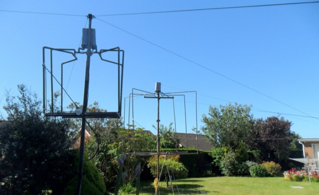 This article describes the development of two tunable antennas each consisting of three interconnected small loops and capable of providing excellent DX performance. The aerials are home-constructed, and located in a very small garden with a minimum of visual impact on the neighbours and are low enough in height to avoid the attention of UK planning authorities.
 -
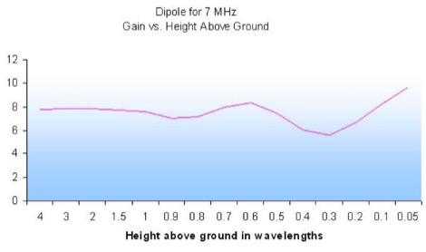 An interesting guide to aerials comparing height, gain and angles
 -
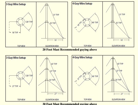 Article based on ROHN engineering specification that will guide on proper guying heights and guy lengths when guying ham radio antenna masts. It will help you determine ahead of time the proper length of guy wires and the distance from the base of the mast to the anchor points
 -
 AN-SOF is a professional comprehensive software tool for the modeling and simulation of antenna systems. AS-SOF allows to describe antenna geometry, Choose construction materials, Describe the environment and ground conditions, Describe the antenna height above ground, Analize radiation pattern and front-to-back ratio, Plot directivity and gain, Analize input impedance and VSWR,Predict antenna bandwidth
 -
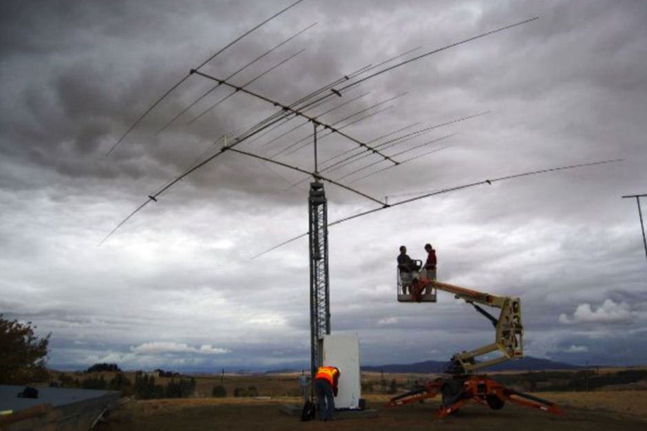 Accessing antennas at great height poses many potential safety hazards. Essentially, climbing ladders or scaling towers, regardless of whether or not a commercial safety harness is fitted, is risky business indeed particularly for those hobbyists in their latter years or not as physically capable as others.
 -
 This article presents an innovative homebrew antenna design utilizing surplus ladder line as a receiving antenna for HF and MF bands. The Ladder Line Antenna (LLA) transforms standard 450-ohm ladder line into a directional, bidirectional, or omnidirectional antenna system through different termination methods. The design, which requires minimal space and height, achieves 6-10dB front-to-back ratio on 40-160m bands using a 33-foot length. This DIY wire antenna project offers an efficient, low-profile solution for amateur radio operators, featuring broadband operation without ground radials and easy installation below fence height.
 -
 An Hentenna project for the six meters band. The standard size of standard hentenna is width 1/6 wavelength x height 1/2. The antenna build in this project is a full wavelenght antenna for the 50 MHz providing a 6.8 dbi gain.
 -
 This page delves into the Inverted V antenna, a source of myths among ham radio operators. The author explores the behavior of this antenna type with a focus on a 20m half-wave dipole positioned 10m above the ground. From Pythagoras to high school math, the article simplifies the calculation of dimensions and angles for setting up an Inverted V antenna. It includes a spreadsheet for calculating hypotenuse length and angles, crucial for antenna setup. Additionally, it provides insight into the radiation pattern of a 'flat' half-wave dipole at 10m height. Useful for hams planning to optimize their antenna setup. In Norwegian.
 -
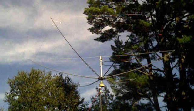
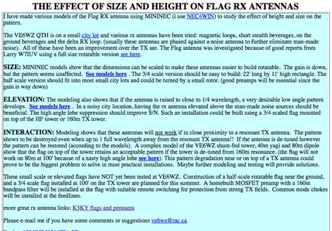 Analysis of flag receiving antennas using MININEC with focus on relation of size and atenna height by VE6WZ
 -
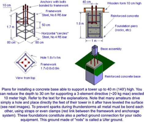 A multiple page article about assembling the antenna system, this section includes informations on constructing of the concrete tower base, starting from setting up correctly the foundations in relation to the antenna height.
 -
 Operating in antenna-restricted communities presents unique challenges for amateur radio operators, often necessitating creative solutions for antenna deployment. This resource details the design and implementation of stealth antennas within a townhouse community in Exton, PA, where external antennas were strictly forbidden by covenants. The author, WB5NHL, describes his setup, which involved locating the shack in the basement and utilizing an unused space under the roofline of a finished third-floor loft for antenna placement. The content specifically addresses the practicalities of routing coax cables three floors and maximizing antenna performance within limited attic space. It covers solutions for multi-band operation, including dedicated sections for 40-10 meter and 80-meter antennas, along with strategies for mitigating potential interference issues. The approach emphasizes full compliance with community covenants, achieving maximum height-above-ground for horizontal antennas, enabling instant band switching, and efficiently utilizing available attic volume. While acknowledging limitations such as potential interference with high power and fixed antenna patterns, the resource provides a detailed account of a functional compromise for restricted environments. Links to individual pages on _coax cables_, _40-10 meter antennas_, _80-meter antennas_, and _interference issues_ offer deeper dives into each specific aspect of the installation.
 -
 Mounting on roof at the right ground level can greately impact on antenna performances because will affect the radiated angle of energy.
 -
 This page presents an online calculator tool for determining the dimensions of various HF wire antennas operating between 1.8-30 MHz. Users input their desired resonant frequency to obtain precise measurements for four popular antenna types: standard flat-top dipole, inverted Vee, quad loop, and equilateral delta loop. The calculator provides comprehensive measurements including leg lengths, minimum heights, horizontal spreads, and feedpoint distances. Accompanying the calculator are detailed technical explanations, construction notes, and installation guidelines for each antenna type, making it a practical resource for amateur radio operators building their own antennas.
 -
 Modeling an antenna over real terrain gives you a visual picture of how terrain impacts performance. You can use a model to determine optimum height for antennas on an existing tower, Compare different tower locations for performance, Compare different sites for performance
 -
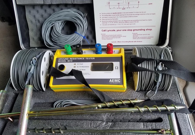
 The mini Radio Solutions miniVNA PRO is the only affordable vector network analyser (VNA) I know of that offers remote wireless operation. This is very interesting because it allows to measure the input impedance of HF antennas installed at height without having to deal with coax cable lengths, baluns nor common mode suppression chokes. However, to render the miniVNA PRO truly field proof, it requires a number of significant modifications.
 -
 This article explores the conventional wisdom about antenna height in amateur radio operations, challenging the common belief that "higher is always better." Through practical examples and computer modeling, it examines how low-height antennas like Beverage antennas, VP2E, and End-Fed Half Wave (EFHW) configurations can perform effectively in various scenarios. The analysis includes radiation patterns and efficiency considerations for antennas at different heights, particularly focusing on portable operations. The article demonstrates that while height affects antenna performance, lower installations can still provide practical and efficient solutions for specific applications, especially in portable and QRP operations.
 -
 The Hex Beam page by W1GQL page, a document dedicated to home brewing hex beam antenna with dimensions, info on spreaders, wires to use, spacing tips, feed line information, mast to use, multi-band version and antenna height
 -
 Discover the success story of creating a 4-meter Delta Loop antenna, ideal for improving radio communication. This horizontally polarized antenna offers efficient performance when mounted at VHF heights, catering to both HF and VHF characteristics. A simple, DIY project suitable for portable setups, providing versatile options for radio enthusiasts.
 -
 Learn how to build a portable receiving antenna for the 160 meter band. This guide provides detailed instructions on constructing a loop antenna using a coaxial cable RG-316 with SMA connectors. The antenna weighs 1.7 kg and has dimensions of 2m in height and 1.892m in width. The wooden frame consists of four 0.945m long pieces and two 1m long pieces. Perfect for hams looking to enhance their 160m band reception during travel or portable operations.
 -
 The Portable EFHW antenna for the 40, 20, 15, and 10-meter bands utilizes a broadband transformer with a 1:49 ratio, designed on a PCB by either Jan or DL2MAN. The design incorporates an **FT114 core**, offering an alternative to the FT82 core. The antenna requires precisely 20.5 meters of DX Wire Ultralight for optimal performance. Additional components include DX Wires "Dyneema" 1mm rope and 1mm bricklayers string for structural support. The SWR plot indicates performance at two elevation heights: 5.5 meters (blue line) and 4 meters (yellow line), demonstrating optimization for low-elevation portable use without poles. The antenna's components, including spool and rope tensioners, are available for 3D printing, with spool dimensions scaled to 130% for a length of approximately 110mm. The design emphasizes simplicity and portability, suitable for field deployment.
 -
 The Beverage on Ground (BOG) antenna offers ham radio operators a compact alternative to traditional Beverage antennas, requiring less space and fewer support structures. This implementation, optimized for 1.8-7 MHz bands, describes ideal parameters: lengths of 60-90 meters, height of 2-10 cm above ground, and specific load resistances based on configuration. The article details experimental methods for determining optimal load resistance and presents matching systems to convert BOG impedance to 50 ohms. While less effective than classic 200-300 meter Beverages, the BOG provides directional reception in limited space, though performance varies with ground conditions and weather changes.
 -
 The LKJ Wednesday Night Special Antenna, designed by John Whiteman K5LKJ, is a compact 50-foot coil-loaded dipole for 80-meter operation, ideal for space-limited hams in residential areas. Using two 1-inch diameter PVC coils with 87 turns of #16 magnet wire each—placed 10 feet from the center—it tunes to 3.910 MHz for local nets like BVARC Rag Chew. Constructed with #14 wire, ceramic insulators, and Mini-8X feedline, it handles 1000W, performs well at low heights for NVIS, and requires a tuner for bandwidth. Collaborative tuning by club members ensured success.
 -
 Delta loop antennas, particularly the 30 meter variant, offer unique advantages in terms of vertical polarization and omni-directional coverage. The construction process detailed by VE3VN highlights common mechanical and electrical challenges faced by amateur radio operators. Key design considerations include minimizing interaction with existing contest band antennas, achieving low elevation angles for DX chasing, and ensuring the antenna remains off the ground for agricultural clearance. The article provides specific measurements, such as the loop's height and feed point impedance, which are critical for optimizing performance. The use of NEC modeling software illustrates the importance of accurate resonance calculations, revealing how proximity to the tower affects both pattern and impedance. This practical account serves as a resource for hams looking to build effective antennas while navigating typical construction hurdles.
 -
 Presents DJ5IL's personal amateur radio station, detailing his journey as a licensed operator since 1973. The resource covers his **shack setup**, including an Elecraft K4D, Icom IC-7610, and various vintage transceivers like the Drake 2-B, along with a SPE Expert 1K-FA amplifier. Antenna systems include a PRO.SIS.TEL RD1524T rotary dipole for 40/20/15/10m at 15m height, an 18m vertical dipole with an SGC SG-230 tuner for 3.5-30 MHz, and an inverted-V dipole for 80m. The site features a **QSL gallery** showcasing his custom card designs and outlines his QSL policy, emphasizing the exchange of unique, personalized cards over generic confirmations. It also includes a detailed operator's biography, tracing his early fascination with radio, obtaining his license at 16, and memorable QSOs, such as a contact with his blood-relative W3NZ. The resource also delves into the historical significance of amateur radio's role in pioneering shortwave communication following the 1912 International Radiotelegraph Convention, which initially relegated amateurs to wavelengths of 200 meters and shorter. DJ5IL's philosophy on "ham spirit" is discussed, stressing the unpolitical nature of amateur radio as a global fraternity.
 -
 This article details an Inverted-L antenna design optimized for 160-meter band operation, consisting of a 10m vertical section and a 28m horizontal section supported by Spiderpoles. Despite its relatively low height compared to the wavelength, the antenna has demonstrated impressive DX capabilities, achieving contacts up to 3,453 miles into Asiatic Russia. The system incorporates a Pi-Network ATU at the base for tuning flexibility. While modeling shows a radiation pattern favoring the South, practical operation indicates effective all-round coverage on Top Band.
 -
 The 2m 7 element Yagi antenna is a perfect beam antenna with 11dB gain and a front-to-back ratio of 20-25 dB. It has seven elements and requires a matching network built of 3/8" aluminum tubing and RG-8 cable. The gamma tube is adjusted to provide the best fit, and the gamma-driven element feeding clamp is tightened. If the beam is vertical, a non-conducting mast is utilized to prevent detuning and skewing of the radiation pattern. For optimal VHF operating, the antenna is installed at a height of 30 feet or higher.
 -
 A full-wave delta loop antenna, approximately 141 feet in total wire length for the 40-meter band, offers a low angle of radiation, which is highly advantageous for DX operations. This design, optimized for both 30m and 40m, leverages a specific circumference calculation of 1005/F, ensuring resonance on both bands through a simple switching mechanism. The antenna's configuration enhances long-distance communication, making it a practical choice for hams with limited space. The resource details the construction process, including the use of a _Ceramic Knife Switch_ for band selection and an _RG-11_ matching section to achieve optimal impedance. It outlines the precise loop lengths required for each band, along with tuning secrets to ensure efficient operation. Requiring a minimum height of 12 feet, this antenna can be supported by a single mast or tree limb, making it suitable for suburban installations where stealth or space constraints are a factor.
 -
 This paper presents an 80 meter wire 3-element beam antenna in an inverted-V configuration, designed for limited-height towers. Using EZNEC modeling, the antenna features a central parasitic reflector and two switchable driven elements at each end, enabling NE/SW coverage without moving parts or networks. Element lengths are optimized for SSB (3.8 MHz) and CW (3.5 MHz) operation, with a 50 Ω feed and rope-supported boom. The design delivers high gain, effective takeoff angles, and excellent reception, confirmed in real-world DX contest operation. Its simplicity, reliability, and ease of construction make it ideal for operators seeking performance without complex matching systems.