Search results
Query: hf power amplifier
Links: 94 | Categories: 3
-
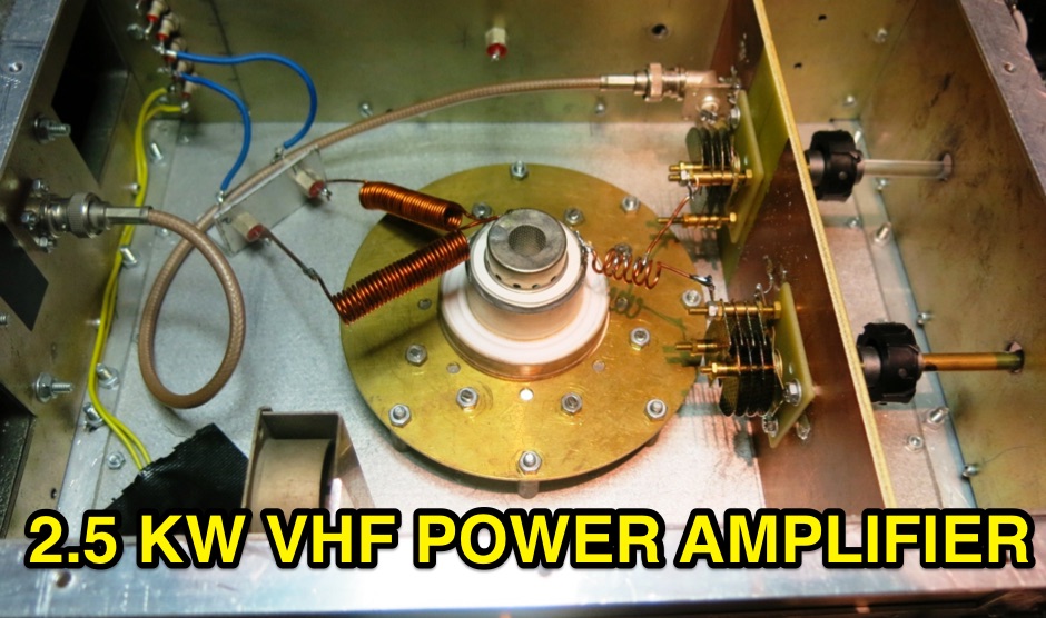 A home made VHF 2.5kw RF power amplifier made with a GS35B Triode and designed by Frank F1CXX built in 2003
 -
-
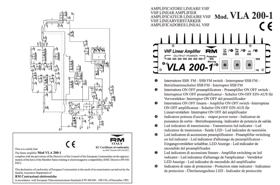 VHF Power amplifier VLA 200 english manual
 -
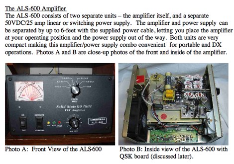 The Ameritron ALS-600 600-Watt HF Power Amplifier review by AD5X
 -
 A complete restoration of a Heathkit SB-200 HF power amplifier
 -
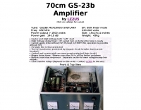 1500 watts of RF output on the 70cm band requires robust amplifier design, a challenge addressed by this project featuring the GS-23b / 4CX1600U Svetlana tube. The resource details the construction of a high-power UHF amplifier, providing insights into component selection and layout necessary for stable operation at these frequencies and power levels.
 -
 Constructing a high-power 70cm solid-state amplifier presents unique challenges, particularly when aiming for 500 watts output using modern LDMOS devices. This resource details the author's experience building a 70cm amplifier based on a _Freescale MRFE6VP5600H_ transistor, initially from an RFHAM kit. It meticulously outlines the necessary modifications to achieve advertised performance, including optimizing input and output matching, correcting bias circuitry, and ensuring proper output balun connections for stability. The author shares specific adjustments, such as trimming the prototyping board for better transistor fit, drilling additional mounting holes for improved heat sinking, and replacing original matching capacitors with a single _20pf MIN02 metal mica_ for superior output. A critical fix involved jumpering gate decoupling pads to balance the push-pull transistor halves, which increased output to 580W and improved IMD. The resource also highlights a crucial correction to the output balun connection, initially reversed in the _Dubus_ article schematic, which resolved intermittent stability issues. Test results are provided, showing input power, output power, and drain current at 50V, demonstrating the amplifier's performance after modifications. This practical account offers valuable insights for hams undertaking similar high-power UHF amplifier projects, especially those working with LDMOS devices and kit-based constructions.
 -
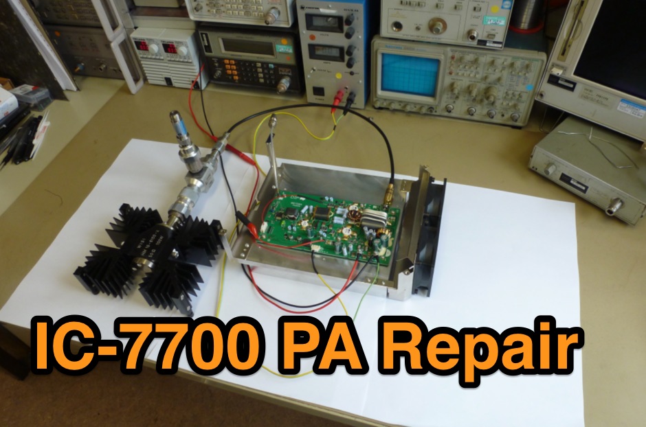 A well documented PDF document containing picture sequence taked during the repair of an Icom IC-7700 HF transceiver power amplifier module
 -
 Excellent article and guide to choose the best RF power amplifier that fit your needs by ON4SKY
 -
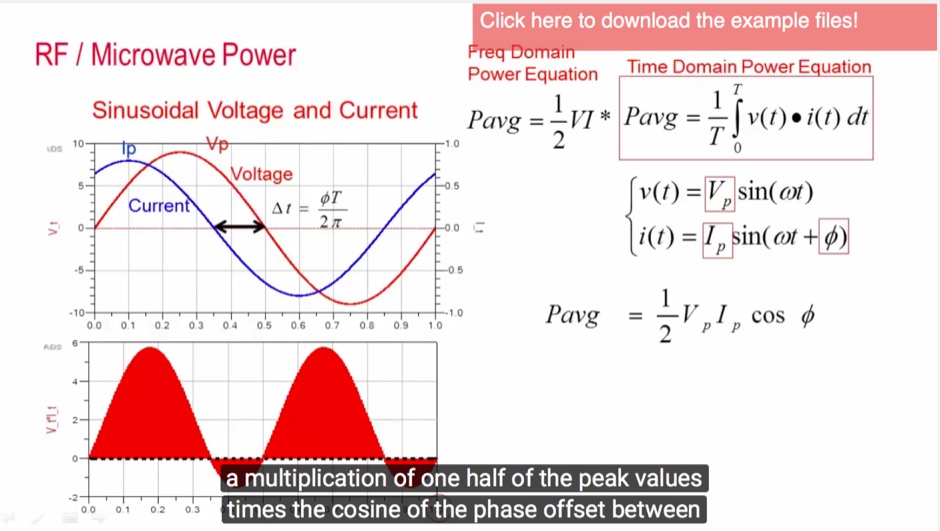 This video will provide a foundation for understanding how power amplifier circuits work. If you are new to High Frequency Power Amplifier Circuit Design, this is the place to start.
 -
 Operating the _Icom IC-746_ HF/VHF transceiver often presents specific technical questions, and this resource compiles a comprehensive Frequently Asked Questions (FAQ) document in an ASCII text format. It details common inquiries and solutions related to the rig's functionality, accessories, and potential modifications. The content is structured into distinct sections addressing general information, power supplies, antennas, microphones, keyers, amplifiers, TNC integration, and optional IF filters. The FAQ provides practical guidance on topics such as configuring the internal automatic antenna tuning unit (ATU), selecting appropriate power supplies, and understanding microphone pin-outs. It also delves into advanced subjects like computer control via CI-V, wiring for PSK31 operation, and troubleshooting common issues like low S-meter readings on 2m FM or loose tuning shafts. Specific questions cover the installation of optional IF filters, comparing Inrad versus Icom filters, and optimizing filter combinations for various modes. Furthermore, the document outlines various hardware and firmware modifications, including those for increasing monitor volume, replacing LCD driver transistors, and implementing a "poor man's TCXO." It even touches upon untested modifications, such as replacing PIN diodes in the demodulator. The FAQ also lists manual errata and discrepancies, offering a robust knowledge base for IC-746 owners seeking to optimize their station or resolve operational challenges.
 -
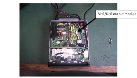 Replacing the Yaesu FT100D SRF7043 VHF/UHF RF MOSFET Power Amplifier
 -
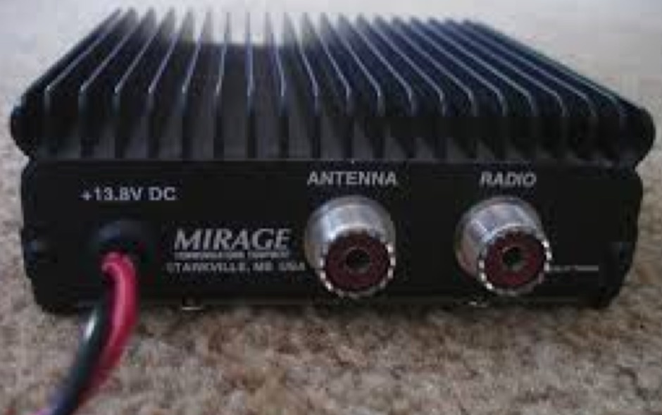 Manual of the BD-35 Dual Band VHF UHF RF power amplifier by Mirage Amp
 -
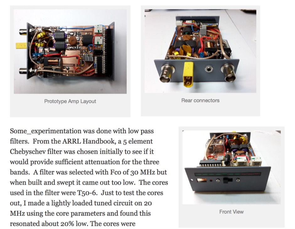
 A 600W 1.8 MHz to 54 MHz power linear amplifier made using rugged MRF300 transistors featuring output power between 580W and 750W depending on band, power supply: 48V, 18A typical, 20A max
 -
 An HF 10-20m portable RF power amplifier based on the RD16HHF1 FETS giving 25 W.
 -
 A synthesized 2.3 GHz Amateur Television (ATV) transmitter design, conceived by Ian G6TVJ, is presented, targeting broadcast-quality video performance on the 13cm band and extending up to 2.6 GHz. The core of the design utilizes a commercial Z-comm Voltage Controlled Oscillator (VCO) that tunes from 2.2-2.7 GHz, providing a +10 dBm output and simplifying RF alignment. This VCO's stability, originally intended for narrowband applications, readily accepts high-frequency video modulation, contributing to the transmitter's robust performance. The exciter stage, incorporating a Mini Circuits VNA 25 MMIC amplifier, boosts the signal to +16dBm, while a Plessey SP4982 prescaler divides the output frequency for the synthesizer. The synthesizer employs a Motorola MC145151 CMOS parallel IC, favored over the common Plessey SP5060 for its superior video modulation characteristics and ease of programming without microprocessors. This choice addresses issues like LF tilt and distorted field syncs often seen with SP5060 designs, particularly when operating through repeaters or over long distances. The MC145151 divides the signal further, enabling precise frequency stepping, with programming handled by EPROMs for channel selection and LED display. The loop filter network, critical for video integrity, was developed through experimentation to prevent the PLL from reacting to video modulation, ensuring a clean transmitted picture. The transmitter incorporates a Down East Microwave commercial power amplifier module, delivering approximately 1.6W output, driven by the exciter through a 3dB attenuator. Construction involves surface-mount SHF components on micro-strip lines etched onto double-sided fiberglass board, housed within a tinplate box. The design boasts no AC coupling in the video path, preserving low-frequency response, a common failing in other ATV transmitters. Performance tests with a 50Hz square wave revealed no LF distortion, and a calibrated "Pulse & Bar" signal showed a near 100% HF response, demonstrating its capability for high-quality ATV transmissions.
 -
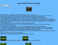 A nice review of the Acom 1000 HF and 6 meter RFpower amplifier by Acom in Dutch and with online google translation available. Includes pictures and notes of the popular amplifier by Acom.
 -
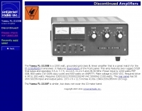 Technical specifications and details of the Yaesu FL-2100B HF Power Amplifier
 -
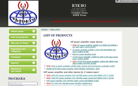 R3KBO is an amateur radio club producing and developing amateur radio kits and assembled products including HF VHF Power Amplifiers or RF Power Kits and amplifier parts, low pass filfers, band pass filters, sourge protections, splitters and combiners, antenna switches
 -
 eHam reviews of the Ameritron AL-811H HF power amplifiers
 -
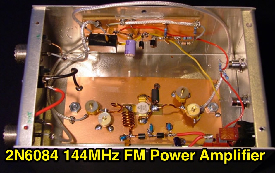 A 144MHz FM class C RF Power Amplifier based on a 2N6084 RF transistor, that can produce 50w output max
 -
 ACOM 1000 160-6m amplifier specifications and features
 -
 The N1HFX thermal cooling fan controller project details a practical circuit designed to manage cooling fan operation based on temperature, a common requirement for high-power amateur radio equipment. This build utilizes a **LM34** temperature sensor, providing a linear voltage output directly proportional to Fahrenheit degrees, simplifying the control logic. The circuit's core functionality involves a comparator that activates the fan when a preset temperature threshold is exceeded, ensuring efficient cooling and reducing unnecessary fan noise. This controller is particularly useful for amplifiers, power supplies, or transceivers that generate significant heat during operation. The design incorporates a _TIP120 Darlington transistor_ to drive the fan, capable of handling up to 5 amps, making it suitable for a range of fan sizes and current requirements. Field results indicate stable temperature regulation, preventing thermal runaway in enclosed environments. Construction involves readily available components, making it an accessible project for hams looking to optimize their station's thermal management.
 -
 RF amplifier products from NP Technologies, Inc. encompass a wide array of specialized designs, including highly linear Class A broadband amplifiers, crucial for maintaining signal integrity across various frequencies. Their portfolio also features cell band amplifiers, specifically engineered for cellular communication infrastructure, and pulse amplifiers, which are vital in applications requiring high-power, short-duration signal bursts. The company's manufacturing capabilities extend to AM and FM broadcast amplifiers, supporting radio transmission systems, and military VHF amplifiers, designed to meet rigorous defense specifications for robust and reliable communications. NP Technologies, Inc. emphasizes comprehensive development, design, manufacturing, and testing processes for all its RF amplifier offerings. This integrated approach ensures that each product, from initial concept to final deployment, adheres to stringent performance and reliability standards. The company's expertise in these areas allows for the creation of custom solutions tailored to specific client requirements, addressing complex RF challenges in diverse operational environments. Their product range demonstrates a commitment to serving multiple sectors, including commercial broadcasting, telecommunications, and defense. The focus on specialized amplifier types underscores their technical depth in RF engineering.
 -
 Demonstrates the construction of a high-power 6-meter (50 MHz) amplifier, specifically designed for demanding modes like EME, TEP, and multiskip Es. It details the use of a _GU-43B_ tetrode in a grounded-cathode configuration, emphasizing the need for stabilized grid voltage and input capacitance compensation. The resource provides a comprehensive schematic, power supply design, and practical considerations for component sourcing, particularly for high-voltage and high-current sections. The builder achieved an output power of **1250 watts** with an anode current of 0.65 amperes and 3200 volts anode voltage. The article also covers the physical construction within a modified P6-31 enclosure, outlining the internal layout for RF and power supply sections, and includes photos of the completed unit. It highlights critical safety precautions for working with high voltages and reactive currents up to **20 Amperes** in the P-network.
 -
 High power, UHF, L-band, S-band, C-band, microwave frequency amplifier and oscillator devices, pulsed, CW, fixed-tuned, or tunable devices in the range of 600 MHz to 2000 MHz
 -
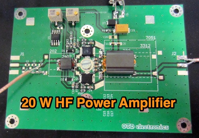
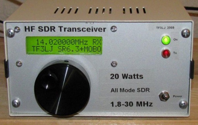 This project describes a DIY all band HF SDR transceiver. Built around a Softrock 6.3 kit, it boasts a 20W homebrew amplifier and ATmega168 microcontroller for USB control. An LCD displays frequency, power, and SWR. Automatic LPF selection and SWR protection enhance functionality. Compatible with Rocky and PowerSDR software, this project provides a cost-effective and powerful HF SDR transceiver for hobbyists.
 -
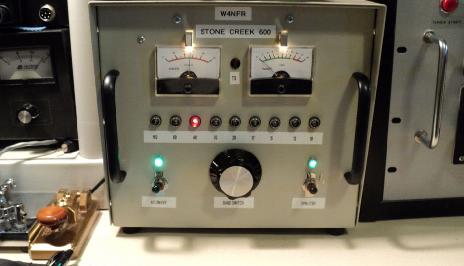 This is a Solid State Amplifier Project. It uses 4 MRF150 MosFet Power Transistors. The Power Supply Voltage is 50 VDC at 21.5 Amp. The max power available is 1,075 Watts. The Efficiency is about 65% +/- and runs Class AB Solid State.
 -
 Voldatech, a manufacturer based in China, produces a range of RF feeder cables and site components essential for amateur radio installations and telecommunication infrastructure. Their product line includes various types of coaxial cables, such as **50 Ohm** and 75 Ohm options, along with a comprehensive selection of connectors like N-type, UHF, and BNC. These components are critical for maintaining signal integrity and minimizing loss in antenna systems, whether for a home shack or a remote DXpedition setup. The company's focus on _RF Coax cables_ and connectors directly supports the needs of radio amateurs seeking reliable transmission lines for their transceivers and antennas. Amateurs often compare Voldatech's offerings to established brands, evaluating factors such as impedance matching, shielding effectiveness, and durability under various environmental conditions. The availability of diverse cable types allows operators to select optimal solutions for different frequency bands and power levels, from QRP to high-power amplifier setups. Their products are particularly relevant for those constructing new antenna arrays or upgrading existing feedline systems, aiming to achieve maximum power transfer and reduce standing wave ratio (SWR) for efficient signal propagation.
 -
 256 memories enable the _AT-AUTO_ to recall settings across multiple bands, making it efficient for operators who frequently change frequencies. The tuner is compatible with various antennas and amplifiers, such as the Mercury LUX, and integrates seamlessly with radios like the FLEX 6400 using an RS232-USB connection. This integration allows the tuner to follow frequency changes without additional input, enhancing operational efficiency. Despite being out of production, the _AT-AUTO_ remains supported by Kessler Engineering, which offers firmware updates and repair services. The tuner features a cross-needle SWR meter, providing quick visual feedback during tuning. It also includes a QRO keyline circuit to protect amplifiers during tuning. Users appreciate the tuner's ability to track radios via CAT control, avoiding automatic tuning during QSOs, a common issue with other models. The _AT-AUTO_ is praised for its durability and performance, with many users noting its reliability over years of use. Its ability to handle legal limit power and its balanced line output make it a versatile choice for serious operators. Although it lacks some features like multiple coax outputs found in other models, its robust build and continued support make it a valuable tool for HF enthusiasts.
 -
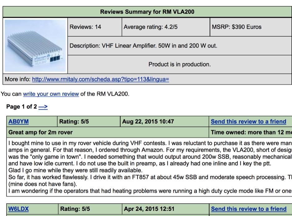 eHam reviews of the RM VLA 200 VHF RF power amplifier
 -
 A HF power amplifier with a push-pull of AFT09MS015N. The (small-signal) gain of the amplifier is around 26 dB in the lower HF band and goes down to about 24 dB on the higher end and still around 21 dB at 50 MHz. Its input matching is relatively good at the lower HF and degrades above 10 MHz.
 -
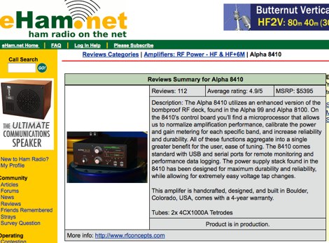 eHam reviews of Alpha 8410 HF power amplifier
 -
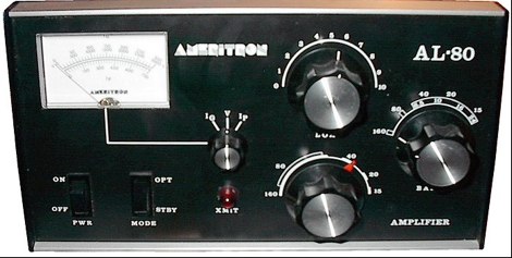 An article on popular AL80 HF power amplifier manufactured by Ameritron since 1980
 -
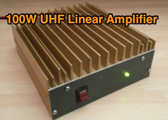 This page details my building of a 100 Watt Power Amplifier for the 432 MHz Band based on two Motorola MRF646 transistors taking inspiration by Carlo Gnaccarini VK3PY, formerly VK3BRZ
 -
 The DX FT8 is a compact, multiband tablet transceiver designed for FT8 digital mode enthusiasts. Supporting five or seven HF bands, it integrates an STM32F746-based touchscreen interface for standalone operation, eliminating the need for a PC. The latest firmware (v1.9.2) adds SOTA/POTA calling and free-text messaging. Its efficient power design, unique RF amplifier, and 3D-printed case enhance portability. Open-source firmware and community-driven development make it a versatile choice for portable FT8 operation, ideal for SOTA, POTA, and travel use. DX FT8 TRANSCEIVER PROJECT is a collaboration between Charles(Charley)Hill, W5BAA and Barbaros(Barb)Asuroglu, WB2CBA.
 -
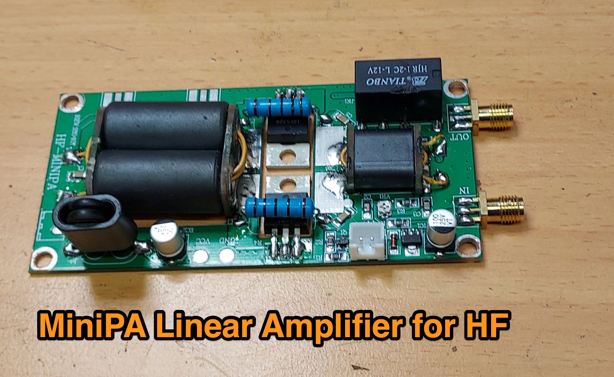 The MiniPA Linear Amplifier for HF page discusses the popularity of QRP for HF among ham radio operators, such as those using the Yaesu FT818 or low power SDR transceivers. It explores the use of cheap kits from eBay or Chinese suppliers to build a 70-100W SSB amplifier using IRF530 MOSFET transistors. The article provides a review of the MiniPA design, including its features, components, and assembly process. It also highlights the importance of using a heatsink and forced air cooling for optimal performance. This page is useful for hams looking to enhance their HF rig with a budget-friendly amplifier.
 -
 his article explores the construction of a PL519 tube amplifier, utilizing Ulrich L. Rohde N1UL's insights. Focusing on a modest 25W continuous output, the design ensures robustness with forced air cooling. The detailed breakdown covers input matching, screen grid voltage generation, bias adjustment, anode power supply, heater power supply, and monitoring circuitry, providing valuable guidance for ham radio enthusiasts.
 -
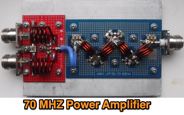 This PA has been designed by Sergey EX8MLE and uses three Mitsubishi RD100HHF1 FETs, Frequency Range 70 to 72 MHz
 -
 Many low-power SSB rigs and kits lack dedicated speech processor circuitry, although most modern HF rigs include it. Speech processing is crucial for low-power SSB to overcome QRM. This simple, low-cost circuit integrates a microphone element and can be housed in a defunct desk mike. It features a feedback amplifier, audio preamplifier, and adjustable speech compression control
 -
 This document provides a comprehensive guide on purchasing high-frequency (HF) high-power amplifiers, discussing key considerations such as new versus used models, tube versus solid-state technology, and troubleshooting common issues. It emphasizes the importance of understanding power needs for activities like DX chasing and contesting, alongside practical tips for selecting and maintaining amplifiers to ensure reliability and performance in various conditions.
 -
 The Olivia digital mode, a **Multi-Frequency Shift Keying (MFSK)** radioteletype protocol, is specifically engineered for robust communication under difficult propagation conditions on shortwave radio bands from 3 MHz to 30 MHz. Developed by Pawel Jalocha in 2003, Olivia signals can be decoded even when the noise amplitude exceeds the digital signal by over ten times, making it highly effective for transmitting ASCII characters across noisy channels with significant fading and propagation phasing. Early on-the-air tests by Fred OH/DK4ZC and Les VK2DSG on the Europe-Australia 20-meter path demonstrated intercontinental contacts with as little as one-watt RF power under favorable conditions. Common Olivia modes are designated as X/Y, where X represents the number of tones and Y is the bandwidth in Hertz, with examples including 8/250, 16/500, and 32/1000. The resource clarifies that Olivia, unlike some other digital modes, produces a constant envelope, allowing RF power amplifiers to achieve greater conversion efficiencies and making it less prone to non-linearity. Operators are advised that **Automatic Level Control (ALC)** can be set higher than no meter movement for MFSK modulation, as long as it's not driven past its high limit, contrary to common misinformation about other digital modes. The Olivia community encourages voluntary channelization on suggested calling frequencies, such as 14.0725 MHz for 8/250, to facilitate initial contacts, especially for signals below the noise floor. The Olivia Digital DXers Club provides links to Groups.io, Facebook, and Discord for community engagement and offers details on QSO parties.
 -
 The Gemini Amplifier Remote Control software operates on Windows 7 and above, facilitating remote management of the Gemini HF-1K and DX-1200 amplifiers. Users connect via Ethernet, configuring the amplifier's IP address through the front panel. The software allows seamless band and antenna selection, saving settings for each band without requiring transmission. Integration with _OmniRig_ from Afreet Software, Inc. enables automatic band adjustments based on the radio's frequency changes. Users can configure serial or virtual serial connections, with tracking options accessible through the ribbon bar. The software supports speech functionality, enhancing accessibility for operators. Firmware updates, such as version 2.5Ee, introduce features like background datalogging and power output control, uploaded via FTP. Version 1.2.0 allows users to offload internal parameter data for support purposes. The firmware upload process requires the amplifier's IP address and port 21, taking approximately 90 seconds. Users are encouraged to upgrade to the latest firmware for improved performance and remote diagnostics.
 -
 This resource details **cooling modifications** for Ameritron AL82, AL1200, and AL1500 HF amplifiers, specifically addressing heat issues encountered during high-duty-cycle digital mode operation. The author, WD4NGB, observed excessive heat in the tank area and band switch on an AL82, attributing it to insufficient exhaust over the 3-500 tubes and a complete lack of exhaust over the tank area. The modifications aim to prevent common failures such as damaged band switches and deformed insulating materials by increasing airflow and exhaust area. The page describes adding five holes to the chassis for enhanced cooling to the band switch and tank area, alongside enlarging the exhaust area over the inner 3-500 tube and the tank area on the amplifier cover, utilizing expanded metal for safety and RF shielding. The original cover featured 26.25 square inches of exhaust; the modified version significantly increases this to 48.5 square inches over the tubes and introduces an additional 15 square inches over the band switch. These changes are intended to resolve heating problems encountered during heavy, 100% duty cycle use in modes like RTTY or long SSB contests, which typically generate substantial heat. The article also discusses upgrading to a higher output fan, such as the G2E085-AA05-21, and modifying tube sockets for improved airflow and reduced back pressure, citing Tom Rauch (W8JI) of CTR Engineering as a source for parts.