Search results
Query: ho loop antenna
Links: 178 | Categories: 0
-
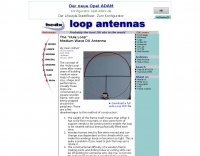
 Constructing a compact, two-band magnetic loop antenna for HF operation, especially from constrained locations like a balcony, presents unique challenges. OK1FOU's design, inspired by DJ3RW's 50 MHz loop, addresses these by employing an unusual side-fed configuration and placing the symmetric, two-section variable tuning capacitor at the bottom of the loop, directly connected to the coax shield. The article provides specific material recommendations, including two 1-meter wooden pales and about 3 meters of thick loudspeaker cable, noting the high current (60A at 100W) in the loop. Construction steps detail forming two turns with a 5 cm gap, using a GDO to pre-tune the open loop to a frequency slightly above the desired highest band, and then integrating the tuning and coupling capacitors. For 10/14 MHz, an open loop resonance of 16-17 MHz is suggested. Practical experience with the 10 MHz band from a third-floor balcony in Prague (JO70GC) shows a 1:1 SWR across most of the band without an external ATU. While DX traffic was modest due to the urban environment, QSO examples with RA6WF, LA6GIA, G0NXA, and LZ1QK on 10 MHz are provided, demonstrating its operational capability.
 -
 JJ0DRC's HF multi-band delta loop antenna project, initially conceived during the waning peak of Cycle 23, addresses the common challenge of achieving effective DX operation from a small residential lot in Japan. Dissatisfied with a ground plane antenna's performance in SSB pile-ups, the author sought a beam-like solution without a tower, drawing inspiration from a JJ1VKL article in CQ Ham Radio Sep. 2000. The antenna, constructed in October 2000, employs two 7.2-meter fishing rods (37% carbon fiber, reinforced with cyano-acrylate glue and aluminum tape) and 1mm enameled wire, fed by an Icom AH-4 external antenna tuner. While the exact beam pattern remains unmeasured, JJ0DRC observed a significantly higher callback rate compared to dipole antennas, particularly on higher bands. The system's circumference length of 15-20m is crucial for maintaining a good beam pattern across HF bands, though performance on lower bands like 80m, 40m, and 30m becomes less directional as the length deviates from a full wavelength. Ongoing maintenance addressed degradation issues, including aluminum tape cracking and wire breakage at connection points due to strong winds (often exceeding 10-15m/s in winter). The author reinforced rod connections with IRECTOR PIPE SYSTEM components and INSU-ROCK ties, and improved wire attachment methods using Cremona rope and epoxy bond to enhance durability.
 -
 HF pedestrian operation using loop antennas by PY1AHD
 -
 The W1TAG LF Receiving Loop is a specialized antenna project for LF reception, designed to mitigate local noise and enhance weak signal pickup on the lower frequencies. This square loop, measuring 6 feet per side, utilizes 14 turns of #12 THHN wire wound on a PVC frame, offering a robust mechanical structure. The design incorporates a series-tuned circuit with a coupling transformer, allowing for tuning from over 400 kHz down to _45 kHz_ using a switched capacitor bank. Construction details include the use of 1.5-inch PVC pipe for the frame, with specific measurements for spreaders and drilled holes for wire threading. The two 7-turn sections of wire are connected at the center, providing an option for a center tap. The loop rotates on a 1-inch steel pipe, enabling directional nulling of noise sources. The tuning unit, housed in a box clamped to the PVC, employs a 1:2 step-up transformer wound on an _FT-82-77 core_ and uses relays to switch capacitance values from 50 pF to 6400 pF, providing precise frequency adjustment. The current setup connects to the shack via 100 feet of RG-58, feeding into a W1VD-designed preamp, with plans for a balanced, shielded twisted pair cable upgrade.
 -
 The concept of the "Hula Loop" came after many years of building medium wave loops of varying size, shape and performance. Usually these loops are constructed on a square wooden frame, with wire being wrapped around the periphery
 -
-
 A copper pipe Hentenna for 144 MHz. The Hentenna, a compact, high-gain loop antenna developed in Japan in the 1970s, offers approximately 5.1 dBd gain, comparable to a three-element Yagi. Adapted for 2 meters, it is crafted from copper pipe for simplicity, affordability, and broadband performance. Requiring no feed-point tuning, its construction involves soldering standard copper fittings. Installation demands non-conductive materials to minimize signal disruption. Versatile for vertical or horizontal polarization, it is ideal for FM, repeater, SSB, or CW applications. This design emphasizes practicality and performance for amateur radio enthusiasts
 -
 For radio amateurs seeking compact and efficient antenna solutions, particularly for restricted spaces or noise reduction, HF loop antennas present a viable option. This resource compiles several articles from the ARRL, detailing the theory, design considerations, and practical construction of various loop configurations. Topics include small transmitting loops, receiving loops, and multi-band designs, often emphasizing their performance characteristics such as directivity, bandwidth, and impedance matching. The collected articles provide insights into the comparative performance of different loop geometries, such as circular versus square loops, and discuss the impact of conductor size and tuning methods on efficiency. Practical applications are explored, including their use in portable operations, stealth installations, and urban environments where noise mitigation is critical. The content often includes construction diagrams, parts lists, and performance data derived from modeling or field tests, enabling hams to replicate or adapt the designs for their specific operating conditions.
 -
 Connecting centre fed antennas, dipoles, yagis, rhombics, loops to coaxial cable, unless care is taken, it is not difficult to end up with feeder radiation resulting in power loss and the radiation characteristics changes
 -
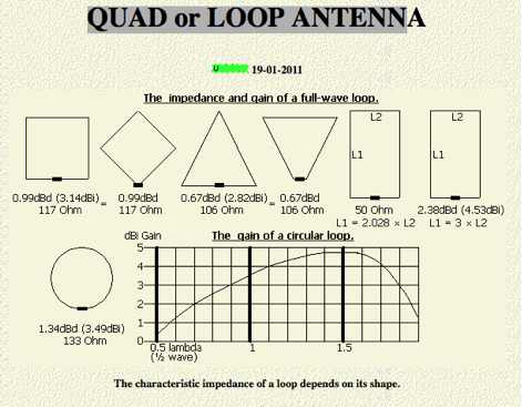 Quad and loop antennas comparisons, evaluating the impedance and gain of both antennas and considerationso n horizontal loop antennas for low bands by PA0FRI
 -
 Demonstrates the construction and measurement of a single-turn HF receiving loop antenna, built from common materials like electrical conduit and lamp cord. The resource details the physical dimensions, including a 4-meter circumference, and calculates the theoretical inductance at approximately _6.4 uH_. It outlines a method for determining resonant frequencies across the 4-17 MHz range using a _C Jig_ and a _VR-500 receiver_, coupling the loop with a ferrite ring. The article also discusses the impact of receiver coupling on the loop's Q factor, noting a degradation in sharpness due to the transformer's reflected impedance. Analyzes the observed resonant frequency patterns, highlighting an unexpected rise in the loop's effective inductance at higher frequencies, particularly above 13 MHz. While some increase is attributed to distributed capacitance, the rate of rise suggests further investigation. The experimental setup provides practical insights into the challenges of maintaining high Q in simple receiving loops and offers a comparative reference for other homebrew antenna projects, such as those by _VK2TPM_.
 -
 Alan yates vk2zay's ham radio website, homebrew construction, general electronics, high voltage experiments, amateur rocketry, and general geek stuff
 -
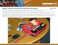
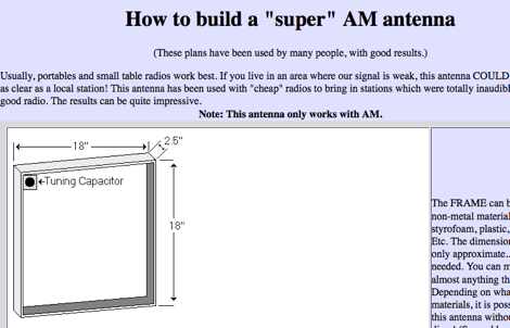 How to build a super AM antenna, These plans have been used by many people, with good results.
 -
 Article using a full wave delta loop antenna at low height, feeding methods, performance reports on 1984 QST article by W1FB and W1SE
 -
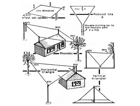 Theory of horizontal loop antennas, as discovered by G2PL using a lowered quad antenna and theorized by ZS6AKA
 -
 Although a magnetic loop antenna(aka small loop antenna) is very compact, its efficiency is close to a half-wavelength dipole if carefully built.
 -

-
 This is the Loop Antenna Group to Ask Your Questions, Get Answers and Information about Loop Antennas for improved your Radio Listening and Enjoyment.
 -
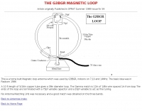 This ia a home built Magnetic loop antenna which was used by G3BGR, indoors on 7,10 and 14Mhz. The basic idea was in Radcom 1986
 -
 An inverted triangle Delta Loop Antenna for the 40 meter band made with aluminium pipes, each element is 14,2 meters including a home made aluminium mount.
 -
 A Loop Fed Array Yagi antenna for 50 MHz featuring 11 dBi gain and 23 f/b ratio. In this excellent page the author even includes a detailed drawing in DWG format, with element lenght and spacing measures, in a separa file a full list of material list needed to build this yagi antenna including source and price, the EZnec file for this antenna plan, and a lot of pictures of this LFA Yagi for 50 Mhz. A ten page PDF file containing all infos, is also available to download.
 -
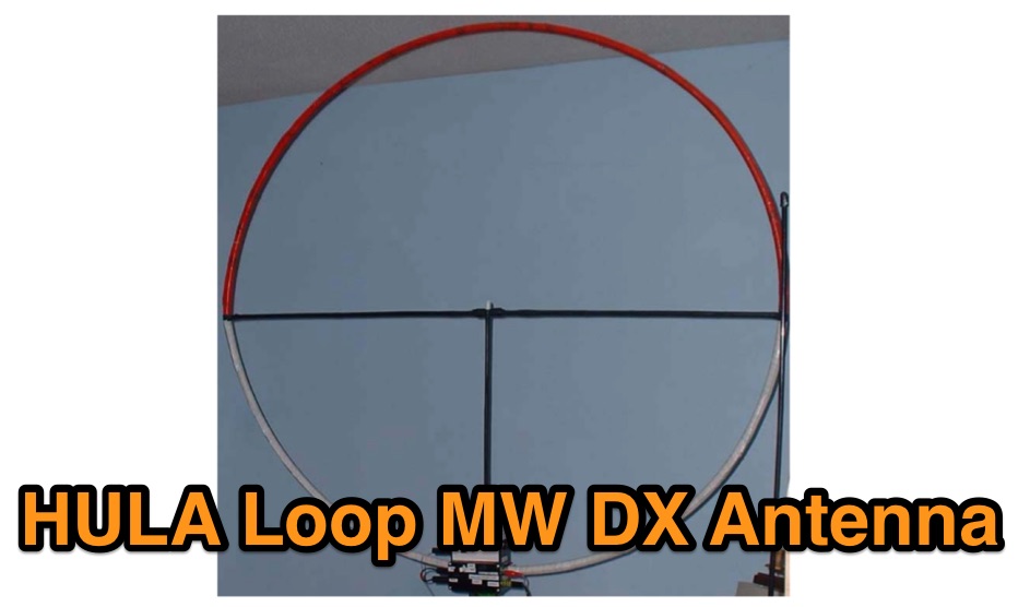 An excellently presented article on the design and construction of a medium wave DX Antenna
 -
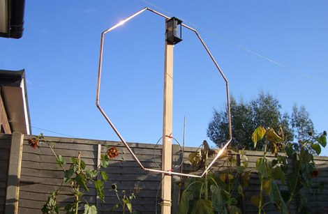
 VK3YE magnetic loop antenna plan that cover 7 Mhz to 20 Mhz and shortening loop can work on 21 Mhz.
 -
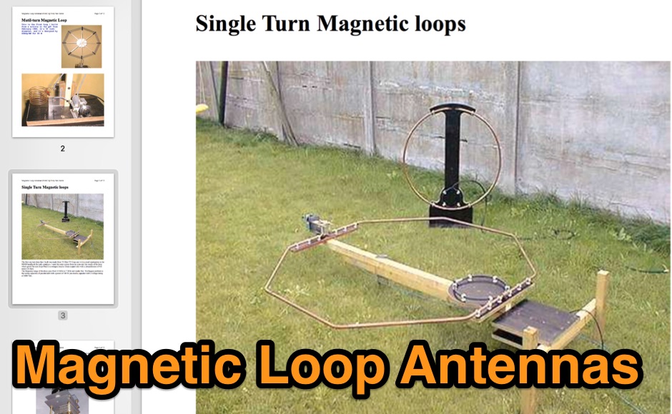 A complete guide to magnetic loop antenna construction, with analysis of multi-turn and single-turn magneti loops, and and insight on choosing the optimal capacitor, or homebrewing your own butterfly capacitor
 -
 An Experimental, High-efficiency, Graphic-Tunable Magnetic Loop antenna and loop controller in a 52 pages PDF presentation with drawings and pictures
 -
 The grounded half loop describe in this article is basically a half wave length wire on 80 Meters. The 80M grounded half loop antenna, inspired by a 1984 QST article by SM0AQW, is a compact solution for limited spaces. Comprising a 127-foot wire fed against ground and supported by radials, it balances performance and practicality. Despite compromises in length and proximity to structures, the antenna delivers strong signal reports and effective multi-band tuning using an SGC 237 antenna coupler. Ideal for CW operation, it offers low SWR on 80-10M, though noise levels and safety considerations warrant attention. This versatile design excels in constrained environments.
 -
 A Wire resonant loop antenna for 160 meters band article by N4KC
 -
 An home made magnetic loop antenna project using a military surplus 150pf capacitor by KF5CZO
 -
 This PDF document details the construction of a **70 MHz** Big Wheel antenna, a horizontally polarized omnidirectional array. The design utilizes three full-wave loops, each approximately **2160 mm** in diameter, arranged in a triangular configuration. The resource provides mechanical dimensions for the antenna elements and a comprehensive bill of materials, specifying component quantities and types, such as M8 stainless steel bolts, 15x15x1.5 mm square aluminum tubing for spacers, and 8 mm aluminum rod for the arcs. The central hub is constructed from two 160x160x8 mm aluminum plates, with four 40 mm long polyamide insulators supporting the radiating elements. The feed system incorporates a 50 mm diameter aluminum pipe for mounting and a matching stub constructed from a 120x20x2 mm aluminum sheet, connected via M8x10 mm bolts. The resource includes a diagram illustrating the mechanical dimensions and assembly points, including the N-connector fixing point and the center conductor attachment. The project was published on May 25, 2011, by Peter OE5MPL and Rudi OE5VRL. DXZone Focus: PDF | 70 MHz Big Wheel | Mechanical Dimensions | **2160 mm** loop diameter
 -
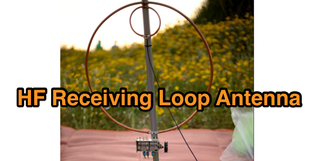 The antenna was built to be used for shortwave listening with a Tecsun PL-660 radio receiver. Later it was used with Yaesu VX-6 handheld transceiver and with Yaesu FT-817ND for shortwave listening.
 -
 The 10-minute, 25-second video demonstrates making a QSO via the VO-52 amateur radio satellite, focusing on real-time Doppler shift correction. It features Simon, 2E0HTS, operating a Yaesu FT-847 transceiver and a homebrew dual-band Yagi antenna, specifically a 10-element 435 MHz Yagi for uplink and an IO Loop for 145 MHz downlink. The video visually details the operator's technique for continuously adjusting the uplink frequency to compensate for the satellite's changing velocity relative to the ground station, a critical aspect of successful satellite communication. The demonstration highlights the practical application of Doppler compensation, showing the operator tuning the transmit frequency to maintain a stable received signal from the satellite. This approach contrasts with systems employing automatic Doppler correction or full-duplex operation, providing insight into manual frequency management for satellite passes. The video serves as a direct, observational guide for hams interested in LEO satellite operations, particularly those using non-tracking, manually tuned setups.
 -
-
 Demonstrates the operational status and reception reports for the SK6RUD/SA6RR QRPP beacons, which transmit on 478.9 kHz, 1995 kHz, 10.131 MHz, and 40.673 MHz. These beacons utilize extremely low power, with the 630-meter beacon operating at approximately 0.1 watt ERP into an L-antenna, showcasing the potential for long-distance contacts under favorable propagation conditions. The site details the specific frequencies and antenna types employed, such as a vertical at 500 kHz and a 1/4 vertical for higher bands. The resource compiles over 10,530 reception reports from amateur radio operators worldwide, logging details such as date, time, band, RST signal report, locator, distance, and receiver setup. Notable long-distance reports include a 500 kHz reception by AA1A-Dave from 5832 km in 2008 and a 10.133 MHz reception by ZL2FT-Jason from 17680 km in 2010, illustrating the global reach of these low-power transmissions. Each log entry provides specific equipment used by the reporting station, including transceivers like the Yaesu FT817, ICOM IC-7300, and various antenna configurations such as coaxial mag loops, inverted Ls, and end-fed wires. The primary objective of the SK6RUD beacons is to challenge conventional notions of power requirements for effective two-way communication, proving that contacts over significant distances are achievable with minimal output. The site also includes a submission form for new reception reports, fostering community engagement and continuous data collection on propagation phenomena across different bands. The detailed logs offer practical insights into real-world propagation characteristics and the efficacy of QRPP operations.
 -
 A system designed to automatically tune small transmitting magnetic loop antennas, particularly beneficial for **contest operations** where rapid frequency changes are common. The core of the system involves a PC-based control application, AutoCap, written in C#, which monitors antenna SWR via an external meter and commands a motor interface to adjust the loop's variable capacitor. The software is compatible with Windows and Linux via the Mono framework, offering a graphical user interface for monitoring system status, SWR, power, and motor commands. Key components include one or more magnetic loop antennas equipped with DC or stepper motors for capacitor adjustment, an SWR meter with data output (such as the Telepost LP-100A or a homebrew serial/USB SWR meter), the AutoCap PC software, and a motor interface. The most effective motor interface utilizes an **Arduino-based controller** with custom firmware, providing precise control over both simple DC motors and stepper motors, and supporting features like motor braking for finer adjustments. The system allows for configurable SWR thresholds, pulse widths, and motor effort settings to optimize tuning speed and resolution. Optional radio integration provides frequency hints, enabling the algorithm to learn the relationship between motor actions and resonant frequency, thereby speeding up initial tuning responses. The software also supports antenna profiles, allowing operators to save and recall specific configurations for different loops, including accumulated frequency hint data.
 -
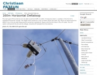
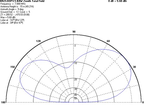
 The HF horizontal loop has been around for many years now. This article includes a YouTube video and discusses the reasons for looking at this antenna, its design, and its installation. There are some on-air comparisons against three regular double bazooka (coax) dipoles and the Par SWL End-Fed antenna.
 -
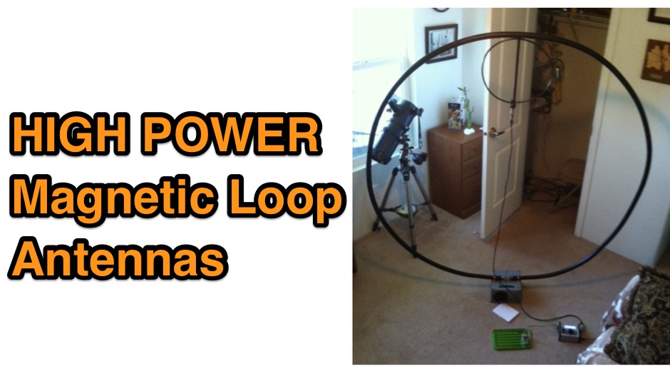 Magnetic Loop Antennas for The Radio Operator with Limited Space, a two part series of articles on how to construct a magnetic loop antenna, including directions on selecting high voltage tuning capacitor
 -
 Loop Antenna Basics and Regulatory Compliance for Short-Range Radio
 -
 A magnetic loop antenna for the VHF band, featuring a high gain that can be compared to a quarter wave vertical antenna
 -
 Antennas and Accessories for Satellite Radio and AM FM HD Short Wave Radio, satellite antenna, shortwave magnetic loops.
 -
 The **136kHz Vertical Antenna** at G3YMC employs a Butternut HF2V structure, standing 10m tall. It integrates a 6.5mH loading coil to achieve resonance, with a matching transformer for impedance adjustment. The antenna's configuration includes top loading via a 12m horizontal wire, enhancing capacitive impedance. Initial measurements indicated a high impedance of around 300 ohms, necessitating a transformer for a 50-ohm match. Despite challenges with ground losses, the vertical antenna has shown improved performance in specific directions, filling nulls present in the previous loop antenna setup. The tuning remains broad, with variations due to environmental factors affecting the matching. Ongoing adjustments and comparisons with the loop antenna will continue to refine its effectiveness.
 -
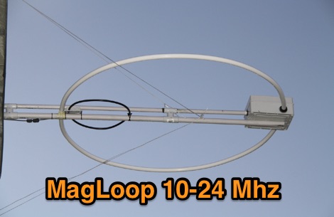
 Experimentig magnetic loop antennas for VHF and HF by M0UKD
 -
 An homebrew project of a full wave delta loop antenna for the 40 meters band with dimensione, picture and assembling instructions in Indonesian
 -
 Magnetic Loop antenna for 20 to 80 meters band using home made butterfly condensator kit
 -
 Simple 6 Metre DX Antenna based on an article by LB Cebick in QST May 2002 on a Quad Turnstile antenna. This antenna is basically two full wave loops mounted at right angles fed 90 degrees out of phase to produce an omni-directional horizontally polarized pattern
 -
 A few pictures of an homebrew magnetic loop RTX antenna project, working from 30 to 12 meters with excellent results
 -

-
 Operating a ham station often involves encountering radio frequency interference (RFI), RF feedback, or RF burns, which are frequently misattributed to poor equipment grounding. This resource meticulously dissects these assumptions, asserting that RF grounds on the operating desk often merely mask more significant system flaws. It identifies five primary causes for RF problems, including antenna system design flaws, proximity of the antenna to the operating position, DC power supply ground loops, equipment design defects, and poorly installed connectors or defective cables. The content emphasizes that issues like "hot cabinets" or changes in SWR when connecting a ground indicate substantial RF flowing over wiring or cabinets, a phenomenon known as common-mode current. The article provides detailed explanations of common-mode current generation, particularly from single-wire fed antennas like longwires, random wires, and OCF dipoles, which inherently present high levels of RF in the shack. It also illustrates how vertical antennas, lacking a perfect ground system, can excite feed lines with significant common-mode current. Through simulations, the author demonstrates how a dipole without a proper _balun_ can cause RF problems at the operating desk, showing current patterns and voltage distributions on feed line shields. The discussion extends to the proper application of _RF isolators_ and _ferrite beads_, clarifying their role in modifying common-mode impedance on cable shields and cautioning against their use as a band-aid for fundamental system defects. The resource advocates for correcting the actual source of RF problems, such as antenna system issues or poor connector mounting, rather than relying on internal shack grounding or isolators. It highlights that properly functioning two-conductor feed lines, like coaxial or open-wire lines, should result in minimal RF levels at the operating position, even without a desk RF ground. The author shares personal experience, noting that his stations since the late 1970s have operated without RF grounds at the desks, relying instead on proper antenna system design and feed line integrity.
 -
 US amateur radio antenna manufacturer. Produce baluns, delta loops, dipoles, ocf antennas and more
 -
 Such kind of omnidirectional antenna gives the possibility to be QRV with horizontal polarisation, as commonly used for the CW and SSB section of the 2m band. This actual design shows a 1.3:1 bandwidth of about 150kHz, centered to 144.200MHz.
 -
 This wire antenna for 40 and 20 meter band feature a good SWR. Horizontal side of the antenna is placed at two meters above the ground. Impedance of the antenna are depending by the height of the base from the ground and conditions of the ground