Search results
Query: irc
Links: 495 | Categories: 21
Categories
- Operating Modes > Aircraft scatter
- Software > Aircraft scatter
- Software > Circuit Design
- Technical Reference > Mircrowave
- Software > ACARS
- Radio Scanning > Aeronautical
- Technical Reference > Batteries
- Technical Reference > Batteries > Battery Charger
- Technical Reference > Electronics
- Manufacturers > Test Equipment > Impedance Analyzers
- DX Resources > QSLing > International reply coupons
- Technical Reference > Morse Code Oscillator
- Technical Reference > Test Equipment > Multimeter
- Software > PCB Design
- Technical Reference > Receiver Front-End Protector
- Software > RF Design
- Technical Reference > Soldering and Desoldering
- Technical Reference > Transverters
- Technical Reference > Vacuum tube
- Software > Vector Network Analyzer
- Shopping and Services > Antennas > VHF Antenna
-
 These devices are called Traps, but they are actually more like frequency sensitive switches. They are parallel resonant, high Q, tuned circuits which provide a very high impedance at their frequency of resonance.
 -
 What type of antenna should I get? Well, the best type of antenna for working the OSCAR satellites are circular polarized antennas
 -
 A lot of good informations concerning antennas, filters, moonbounce, and circuitry data.
 -
 PDF resources containing information on low cost ssb,am,cw circuits, which are useful for beginners.
 -
 The Elecraft K3, a popular HF transceiver, is often benchmarked against new market entrants. This article critically compares the Kenwood TS-590S to the K3, focusing on key technical specifications and operational aspects relevant to serious amateur radio operators. The author proposes three distinct evaluation methods: a circuit diagram comparison, an independent review analysis (referencing Peter Hart, G3SJX, in RadCom), and a real-world "ear test" by experienced contest operators on 40 and 80 meters. The analysis delves into specific receiver components, including the first mixer design, RF and IF amplifier performance, and the presence of an image noise filter. It highlights the K3's switched mixer and the potential for the TS-590S to utilize similar or improved designs, such as a classic filter with enhanced selectivity. The article also scrutinizes the second mixer stage, noting the K3's SA612 chip and its associated IP3 limitations, suggesting Kenwood might achieve benefits with a different mixer architecture. Further points of comparison include DSP capabilities, where the K3's high-performing DSP with KK7P's involvement is noted against the TS-590S's potential reliance on newer IC technology but possibly less refined software. The discussion extends to DDS and PLL implementations for phase noise and spurious emissions, and the utility of a second receiver for DX chasing and contesting, acknowledging its importance for some operators while being less critical for others. The article concludes by emphasizing personal preference in equipment selection.
 -
 Demonstrates the construction of a **homebrew spectrum analyzer** designed by Wes Hayward, W7ZOI, and Terry White, K7TAU, enabling radio amateurs to build a capable test instrument without significant expense. The resource details a _double-conversion superheterodyne_ circuit, employing intermediate frequencies of 110 MHz and 10 MHz, and covers essential blocks such as the time base, logarithmic amplifier, resolution filters, and local oscillators. It highlights the use of hybrid and monolithic ICs, including mixers, amplifiers, and VCOs, to simplify construction while maintaining performance. The design supports useful measurements in the 50 kHz to 70 MHz range, with methods outlined for extending capabilities into VHF and UHF. The authors emphasize that this analyzer, while simple to build, is intended for serious measurements, requiring careful control of signal levels to avoid spurious responses. It uses an oscilloscope for display, with specific instructions for calibration and adjustment of various stages, including the log amplifier and IF gain. The guide provides detailed schematics and component lists for each section, such as the 110 MHz triple-tuned band-pass filter, which achieved **90 dB** image rejection, a significant improvement over double-tuned circuits. Practical advice on alignment and troubleshooting is included, drawing on the authors' extensive experience in RF circuit design.
 -
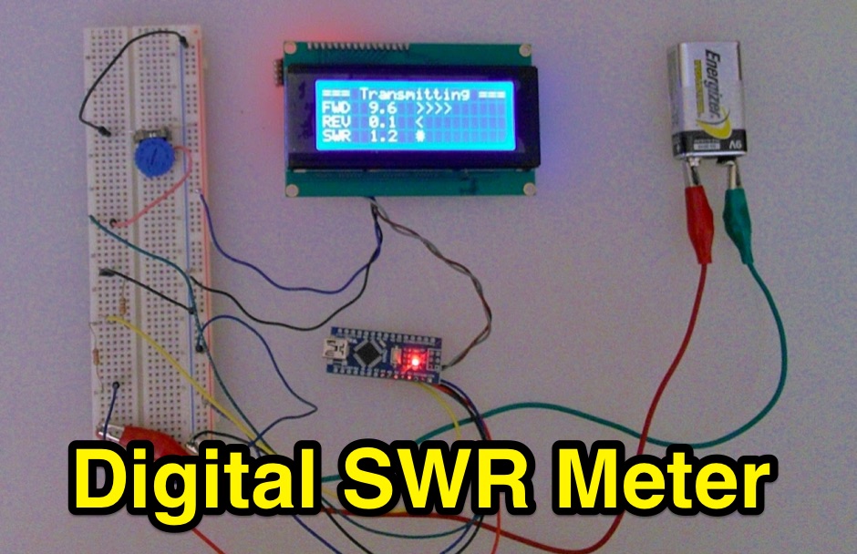 Inline RF Power & VSWR Meter. A DIY meter 0 to 30 Watt with Average and Peak. Circuit Description, Arduino Nano software code and part list to DIY your own Digital SWR Meter
 -
 End-Fed Half-Wave Antennas (EFHWAs) are analyzed for their utility in portable QRP operations, emphasizing their simplicity, efficiency, and predictable radiation patterns compared to other portable antenna types. The discussion contrasts EFHWAs with vertical antennas, random length wires, and center-fed dipoles, highlighting the common pitfalls of each, such as ground system dependency for verticals and feedline issues for dipoles. The article details the electrical half-wavelength calculation using the formula L (Ft) = 468/F(MHz) and explains how EFHWAs can be resonant on harmonic frequencies, enabling multiband operation. Various deployment configurations are presented, including the inverted L, inverted Vee, sloping wire, and vertical setups, each with specific advantages for radiation angle and polarization. For instance, a vertical EFHWA offers a low angle of radiation suitable for DX contacts without requiring an extensive ground system. The resource also addresses the counterpoise requirements, suggesting a quarter-wavelength wire or connection to a metallic structure for decoupling. A schematic diagram for a simple parallel-tuned circuit tuner, based on the _Rainbow Bridge/Tuner_ design, is provided, detailing component values for 30 and 40 meters, including a 6 microhenry toroidal inductor and a 20-100 picofarad mica compression capacitor. The tuner's adjustment process for SWR matching is also outlined.
 -
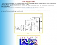
 When one operates at low power on SSB, speech processing becomes almost essential to get through the QRM. The circuit is a low cost speech processor that will perform well with a minimum of construction effort.
 -
 Details a practical QRP wattmeter construction, leveraging a simplified SWR meter design by JA6HIC. The project focuses on a forward-only power measurement circuit, providing a functional instrument for RF power levels from milliwatts up to 5 watts. It maintains a 50-ohm input and output impedance, suitable for typical QRP transceivers and antenna systems. The resource includes the schematic for the "VSW" (Very Simple Wattmeter) and outlines a six-step alignment procedure. This calibration process involves using a known RF source up to 5W, setting full-scale deflection, and marking power increments. It also addresses minimizing frequency effects on readings with a 100pF trimmer capacitor, noting that measurement error is highest at the lower end of the scale. Construction notes mention using a piece of RG-213 coaxial cable for the inductance and coupler, with the wattmeter assembled in early 2003. The author provides an example measurement showing 0.8W into a dummy load and 1W into a 3-element beam.
 -
 Transceivers, Receivers and some Equipment for Amateur, CB, maritime and aircraft with world wide shipping,
 -
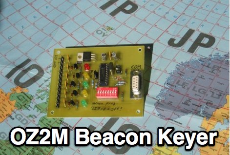 Circuit and software to build a beacon keyer, includes downloadable packages.
 -
 PA3FWM's software defined radio (SDR) page documents his extensive hardware and software development efforts between 2004 and 2009. Initial experiments utilized a direct conversion receiver with 90-degree phase difference, feeding a PC soundcard at 48 kHz sample rate, covering 24 kHz of spectrum around a 7080.5 kHz local oscillator. This setup, similar to AC50G's QEX 2002 article, allowed for basic I/Q signal processing to distinguish signals above and below the LO frequency. Limitations included fixed crystal frequencies, 16-bit dynamic range, and narrow bandwidth. Subsequent hardware iterations aimed for enhanced performance, incorporating external 24-bit ADCs with 192 kHz sample rates, connected via 10 Mbit/s Ethernet. A **MC145170-based PLL** and programmable octave divider provided a 58 kHz to 30 MHz tuning range. The **Tayloe mixer** was employed, with differential outputs feeding a PCM1804 ADC. An ATmega32 microcontroller handled serial data conversion to Ethernet frames, though without CRC calculation due to processing constraints. Later designs integrated AD7760 2.5 Msamples/second ADCs and a Xilinx Spartan-3 FPGA, enabling direct reception of 0-1 MHz spectrum and eventually 2.5 MHz bandwidth across the shortwave spectrum. Software was refactored to use an initial 8192 non-windowed FFT for efficient high-bandwidth processing. The project culminated in a two-way QSO on 21 MHz using the developed hardware and software, demonstrating transmit capabilities with a D/A converter. The system exhibited a 2.5 MHz wide spectrum display and a zoomed 19 kHz display, capturing signals like ionospheric chirp sounders and RTTY contest activity. Challenges included noise leakage from digital circuitry and cooling for high-power dissipation components.
 -
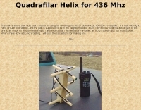 This is an antenna that author just built. Was intend for receiving the AO-27 downlink (at 436.800 +/- doppler). It is built with right hand circular polarization, and the gain is supposed to be in the neighborhood of 3 DB.
 -

-
 Interactive great circles and QRA Locator map
 -
 Free Russian hamradio server special for radiofanats from CIS. Search engine on callsigns, electronic circuits and hamradio programs in www powered with knowledge base.
 -
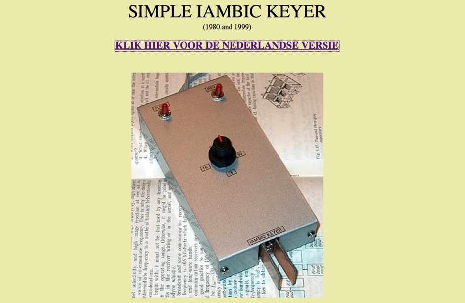 Iambic keyer with simple paddles and simple electronic circuit.
 -
 A simple circuit to homebrew your own headset for the Yaesu FT-817
 -
 Offer Aluminium tubes for antenna parts
 -
 The Emtech ZM-2 Antenna Tuner is a nifty little portable transmatch for QRP (low power). It utilizes the well-known Z-match circuit, which is especially useful for balanced antennas (like dipoles and loops).
 -
 Modifying the _ICOM IC-706MKII_ transceiver for out-of-band transmit capability involves specific surface-mount device (SMD) removal on the main circuit board. This procedure enables transmit functionality from 0.5 MHz to 200 MHz, excluding the commercial FM-Wide broadcast band, significantly expanding the radio's operational frequency range. The modification requires careful handling of small components and a fine-tipped, low-wattage soldering iron. Prior to beginning, all programmed memories and initial setup configurations must be noted, as the modification process will erase them. The instructions detail the necessary tools, preparation steps, and the precise location of the two SMD diodes to be removed. These diodes are situated near an oblong crystal can and a test point labeled _CP3_ on the main board. Successful completion returns the unit to its default configuration, necessitating manual reprogramming of memory channels and initial settings. This project is suitable for operators with experience in SMD work and fine soldering.
 -
 Pictures and circuit diagramm to build this power amplifier for 2 meters
 -
 A broadband travelling wave dipole for HF bands, whose VSWR is less than 2:1 from 3 to 15 MHz and does not exceed 2.6 to 1 from 2.3 to at least 30 MHz
 -
 Electronic circuit and components layout fot this VHF Preamp
 -
 One of the most popular Ham-lore rumors is a balun's performance can be tested or evaluated by grabbing the coax and watching for an SWR change. This is probably one of the worse test-rumors circulating
 -
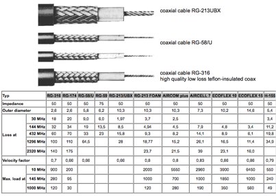 A page with several coax cable characteristics comparison. Includes RG-316 RG-174 RG-58/U RG-59 RG-213/UBX RG-213 FOAM AIRCOM plus AIRCELL 7 ECOFLEX 10 ECOFLEX 15 H-155
 -
 GRIDX, a BASIC program that calculates grid squares and Great Circle headings and grid.exe, a grid locator calculator
 -
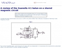 This article reviews the proposition that a 4:1 current balun in the style of Guanella can be constructed with both pairs of windings sharing a common magnetic circuit.
 -
 Constructing a Lindenblad antenna for 137MHz NOAA satellite reception involves specific design considerations for optimal performance. The resource details the use of 4mm galvanised steel fencing wire, 300-ohm television ribbon cable, and wood/plastic components for the antenna structure. Key dimensions for a 137.58MHz-resonant antenna are provided, derived from the ARRL Satellite Handbook, specifying s, l, w, and d as 42, 926, 893, and 654mm respectively. The antenna is designed for Right Hand Circularly Polarised (RHCP) signals, requiring the four folded dipole elements to be tilted clockwise by 30 degrees. A significant aspect covered is impedance matching between the antenna's 75-ohm impedance and a typical 50-ohm receiver input. A twelfth-wave matching transformer, constructed from 117mm sections of 50-ohm RG-58 and 75-ohm RG-59 coax with a 0.66 velocity factor, is described. The article also addresses coaxial cable and connector selection, recommending 75-ohm Type-N connectors for RG-6 cable in professional setups and F56/F59 connectors for general use, while strongly advising against PL-259/SO-259 connectors for VHF. Strategies for mitigating Radio Frequency Interference (RFI) are discussed, including antenna placement to shield from local TV transmitters and the use of commercial or DIY band-pass filters, such as cavity resonators or helical notch filters, along with ferrite chokes on coaxial cables. Antenna orientation is explored, noting the Lindenblad's 'cone of silence' directly overhead and its maximized sensitivity towards the horizon. An experimental vertical tilt of 90 degrees is presented as a method to improve overhead reception and reduce interference from strong horizontal signals, particularly relevant in high RFI environments like the Siding Spring Observatory site.
 -
 A circular waveguide calculator for designing cantennas include source code and windows executable by lincomatic
 -
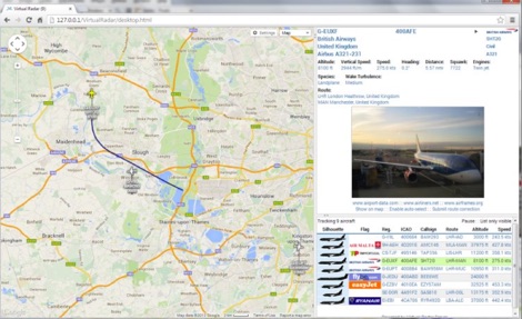 Virtual Radar Server is a free windows decoder of ADS-B signals received by several radio receivers and support even networked data feed. The Server publish a Google Maps-based display of aircraft positions and flight list
 -
 Presented here is a high-performance, circularly polarized omni-directional antenna that is easy to build, easy to tune, inexpensive, and will work all the mode J Low Earth Orbit (LEO) satellites
 -
 Presents the design and construction of the OK2FJ Bigatas, a portable, automatically tuned vertical antenna covering 80 through 10 meters. It details two distinct control systems: one utilizing BCD band data from Yaesu FT-857/897 transceivers, and another employing voltage level sensing for the Yaesu FT-817. The resource provides specific instructions for building the antenna's radiating element, loading coil with switchable taps, and the control circuitry, emphasizing the use of readily available components. The article outlines the physical construction of the antenna, including the use of duralumin tubes for the radiator and a PVC tube for the coil form. It specifies coil winding details, tap points, and the integration of radial wires for ground plane operation. The control electronics section provides schematics and component lists for both the BCD decoder (using a 74LS42 IC) and the voltage comparator (using an _LM3914_ bargraph driver), enabling rapid, automatic band switching without the minute-long tuning delays common in other systems. Crucially, the antenna achieves rapid band changes, with typical SWR values centered on common operating segments, such as **3.7 MHz** for 80m SSB. It also discusses modifications for CW operation on 80m and the trade-offs between antenna efficiency and full-range automatic tuning on higher HF bands, where manual adjustment of radiator length is suggested for optimal performance on 15m, 12m, and 10m. The resource includes construction photos and a discussion of cable requirements for reliable operation.
 -
 JJ0DRC's HF multi-band delta loop antenna project, initially conceived during the waning peak of Cycle 23, addresses the common challenge of achieving effective DX operation from a small residential lot in Japan. Dissatisfied with a ground plane antenna's performance in SSB pile-ups, the author sought a beam-like solution without a tower, drawing inspiration from a JJ1VKL article in CQ Ham Radio Sep. 2000. The antenna, constructed in October 2000, employs two 7.2-meter fishing rods (37% carbon fiber, reinforced with cyano-acrylate glue and aluminum tape) and 1mm enameled wire, fed by an Icom AH-4 external antenna tuner. While the exact beam pattern remains unmeasured, JJ0DRC observed a significantly higher callback rate compared to dipole antennas, particularly on higher bands. The system's circumference length of 15-20m is crucial for maintaining a good beam pattern across HF bands, though performance on lower bands like 80m, 40m, and 30m becomes less directional as the length deviates from a full wavelength. Ongoing maintenance addressed degradation issues, including aluminum tape cracking and wire breakage at connection points due to strong winds (often exceeding 10-15m/s in winter). The author reinforced rod connections with IRECTOR PIPE SYSTEM components and INSU-ROCK ties, and improved wire attachment methods using Cremona rope and epoxy bond to enhance durability.
 -
 Remote Control Antenna Switch made with two circuits board
 -
 Here is how to adjust this popular tuner circuit so it transfers maximum power to your antenna without going snap
 -
 The W1TAG LF Receiving Loop is a specialized antenna project for LF reception, designed to mitigate local noise and enhance weak signal pickup on the lower frequencies. This square loop, measuring 6 feet per side, utilizes 14 turns of #12 THHN wire wound on a PVC frame, offering a robust mechanical structure. The design incorporates a series-tuned circuit with a coupling transformer, allowing for tuning from over 400 kHz down to _45 kHz_ using a switched capacitor bank. Construction details include the use of 1.5-inch PVC pipe for the frame, with specific measurements for spreaders and drilled holes for wire threading. The two 7-turn sections of wire are connected at the center, providing an option for a center tap. The loop rotates on a 1-inch steel pipe, enabling directional nulling of noise sources. The tuning unit, housed in a box clamped to the PVC, employs a 1:2 step-up transformer wound on an _FT-82-77 core_ and uses relays to switch capacitance values from 50 pF to 6400 pF, providing precise frequency adjustment. The current setup connects to the shack via 100 feet of RG-58, feeding into a W1VD-designed preamp, with plans for a balanced, shielded twisted pair cable upgrade.
 -
 Engaging in **QRP** operations, where amateur radio transceivers transmit at five watts or less, presents a unique challenge and satisfaction for many radio amateurs. This mode emphasizes efficient antenna systems, keen operating skills, and often, the art of **homebrewing** equipment to maximize performance under power constraints. Operators frequently utilize CW (Morse code) for its superior signal-to-noise ratio, enabling reliable contacts over long distances with minimal power. The VK QRP Club, formally known as the CW Operators' QRP Club Inc., serves as a focal point for Australian amateurs passionate about these low-power pursuits. The club fosters a community where members can share insights on antenna design, circuit construction, and operating techniques specific to QRP. It provides resources such as information on club nets and frequencies, Morse practice materials, and a platform for exchanging ideas among enthusiasts. Membership offers access to a network of like-minded individuals, promoting the continued development and enjoyment of QRP within the amateur radio hobby. The club's activities encourage experimentation and skill refinement, vital aspects of successful low-power communication.
 -
 Provide components to the amateur who wants to construct their own gear and to the professional who wants to save money and time in prototyping their circuit design, Filters, HF Amplifiers, Splitter Combiners, VHF Amplifiers, ATV
 -
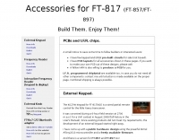 An external keypad for FT-817(ND), for the serious portable/field-day contester/operator. Homebrew it with the free firmware and public circuit diagram. The circuit is very simple and takes power supply from the ACC port of the radio
 -
 Morse Tutor is a DOS based program written in C++. It can be used to practice morse code. Various options are available. Morse tutor with Complete Source Code and Binary is available for Download (32KB).
 -
 Need a variable power supply that is short circuit protected and over voltage protected; Here is a good one that can be built cheap by VE3IVJ
 -
 Circuit of the Kenwood IF-10D interface for the TS-50 transceiver.
 -
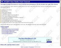 Information on how to access the IRC #CQDX chat room for DXers. Also contains a live feed of DX spots directly from DX Summit.
 -
 Demonstrates the essential steps for winding **toroidal cores**, a fundamental skill for amateur radio operators engaged in homebrewing and kit building. It addresses the critical aspects of selecting the correct core material and wire gauge, emphasizing the importance of precise turn counting and consistent winding tension to ensure optimal circuit performance. The resource details methods for preparing the wire, including techniques for safely removing enamel insulation from leads using flame, sandpaper, or a solder pot, and provides guidance on tinning the exposed wire. Explains the process of mounting the wound toroid onto a printed circuit board, highlighting the need for careful lead placement and secure soldering to prevent shorts and ensure mechanical stability. It also offers a practical formula for calculating the required wire length based on the desired number of turns and the specific **toroid** size, referencing common core types like T-50 and FT-240. The guide stresses the importance of verifying the inductance of the wound component, often using an inductance meter, to confirm it matches design specifications. Provides practical tips for handling multi-filar windings and managing short lead lengths, which can be particularly challenging. It underscores the necessity of meticulous attention to detail throughout the winding and installation process to achieve reliable and efficient RF circuits.
 -
 Circuits, pictures and data about toroids, tubes and home made power amplifiers
 -
 Free PCB software is a snap to learn and use. For the first time, designing circuit boards is simple for the beginner and efficient for the professional.
 -
 Demonstrates the construction of two distinct wideband RF preamplifiers, detailing their component requirements and performance characteristics. The first design leverages monolithic microwave integrated circuits (MMICs) such as the MAR-6, MAR-8, or PGA103, offering a broad frequency response from DC to 2 GHz with a gain of 22.5 dB at 100 MHz and a noise figure typically below 3 dB. This MMIC-based amplifier incorporates protection against power supply transients and features a 50 Ohm input/output impedance, operating from an 8-20 volt supply with low current drain. The second preamplifier design utilizes a BSX-20 transistor, providing amplification across the 14 MHz to 550 MHz range. This simpler, more economical build achieves an average gain of 12 dB at 145 MHz and a noise figure of approximately 1.1 dB. It operates from a 7-15 volt battery supply with a current draw of 6 mA. Both projects emphasize critical construction techniques, such as maintaining short RF connections, ensuring 50 Ohm impedance paths, and mounting the circuit within a shielded enclosure to optimize performance and minimize noise. The resource also discusses phantom power options for antenna-mounted preamplifiers and precautions for use with transceivers, including output protection diodes and static bleeders.
 -
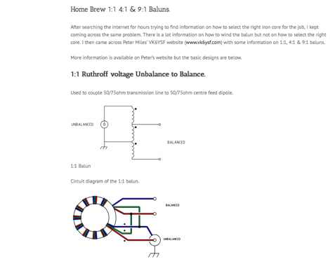 Circuit diagrams to homebrew different baluns by vk2awx