Search results
Query: one element antenna
Links: 63 | Categories: 0
-
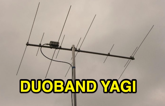 Duoband Yagi 2m/70cm with 4 Elements on 2 m and 5 Elements on 70 cm and one Feed point. The 4-El.-Ultralight-Yagi for 2m can be used on 70cm with an SWR of 1,5 without any changes.
 -
 A coaxial cable trap is a fundamental component in multiband antenna design, enabling a single radiator to resonate efficiently on multiple frequencies by electrically shortening or lengthening the antenna element. This project focuses on constructing such a trap for a vertical antenna operating on the 10 MHz (30m) and 14 MHz (20m) amateur bands, providing practical insights into its fabrication and integration. The article outlines the specific dimensions and winding techniques for the coaxial trap, emphasizing the use of readily available materials. It details the physical construction of the vertical element, including the mast and radiating sections, to achieve optimal performance across both target bands. The author shares personal experiences with similar trap designs, noting their effectiveness in previous horizontal dipole configurations. Key construction steps are illustrated with _original photos_, showing the assembly of the trap and its incorporation into the overall antenna structure. The design aims for a compact footprint, making it suitable for limited space installations while still delivering effective DX capabilities on the **30-meter** and **20-meter** bands.
 -
 Learn about the practical design and construction of Yagi antennas for ham radio operators. This post explores the benefits of Yagi antennas in receiving and transmitting RF signals, concentrating signal energy in one direction for long-distance communication. Discover the theory behind Yagi antennae, the importance of element size and spacing, and the resources available for sizing and construction. Whether you're interested in OTA television or amateur radio communication, understanding Yagi antenna design can enhance your signal reception and transmission capabilities.
 -
 This project involves constructing a dual-band Moxon antenna, optimized for ham radio enthusiasts, with functionality on both the 10-meter and 6-meter bands. The antenna is designed to operate using a single 50-ohm feedpoint, acting as a mini-beam on 28 MHz (10 meters) and as a 2-element Yagi on 50 MHz (6 meters). Performance-wise, it offers a 4.0 dBd gain on 10 meters and 4.3 dBd on 6 meters, with impressive front-to-back ratios of 30 dB and 11 dB, respectively. Builders like Aleks (S54S) and Marcio (PY2OK) have successfully brought this design to life using the provided specifications. Aleks noted that bending the corners of the structure proved especially useful during assembly. The project comes with a detailed parts list, highlighting the use of aluminum tubes with different diameters and lengths to form essential components like the reflectors and radiators. For those looking to fine-tune the antenna, adjustments can be made by altering the length of certain parts that fit into larger tubes. The feeding system is equipped with a balun to accommodate different power levels, making the design versatile enough to handle outputs of either 300 watts or 1 kilowatt.
 -
 The article describes the construction of a Lindenblad antenna, which is well-suited for receiving signals from low-orbiting weather satellites. The key points are: The Lindenblad antenna has an omnidirectional horizontal radiation pattern and is optimized for low to medium elevation angles, making it ideal for tracking passing satellites near the horizon. It is designed to receive circular polarization, which is common for weather satellite signals. The antenna is constructed using 4 folded dipole elements arranged on a cross-shaped frame. The necessary materials include a plastic junction box, PVC tubing, and aluminum rods to form the dipole elements. The article provides detailed instructions for preparing the components, assembling the dipoles, and connecting the feed lines to create the complete antenna. The completed antenna can be mounted on a vertical support, with the dipole elements angled at 30 degrees from horizontal, to optimize reception of the passing satellites. The author notes that the design was originally published in a now-defunct magazine, Meteo Satellite Inf", in 1993
 -
 This DIY guide details constructing a 5-element Yagi antenna for VHF frequencies. Yagi antennas offer directional signal transmission/reception compared to omnidirectional ones. The guide covers material selection (aluminum, screws, etc.), design using software or formulas, and step-by-step assembly including cutting elements, drilling holes, and attaching the coaxial cable. While calculations are provided for a 146 MHz design, adjustments are necessary for different frequencies. Safety precautions and potential result variations are emphasized.
 -
 For amateur radio operators engaging in portable operations like SOTA or POTA, rapid deployment of an effective antenna system is paramount. This video resource details the assembly process for the Buddipole multiband dipole antenna, showcasing its components and how they fit together. Rob, VK5SW, systematically presents the mast, coil arms, radiating elements, and the VersaTee hub, emphasizing the modular design that allows for quick configuration changes across various HF bands. The demonstration highlights the antenna's adaptability for different operating environments, from a ground-mounted vertical to a horizontal dipole. The video illustrates the ease with which the antenna can be packed and deployed, making it a practical choice for activations where setup time is limited. The Buddipole's design facilitates efficient band changes and tuning, crucial for maximizing QSO opportunities during field operations.
 -
 The Butternut HF2V, originally a two-band vertical antenna for 80m and 40m, was enhanced by the user to include 30m and 20m bands for better digimode DX work during the solar minimum. The additions used components adapted from the HF6V and innovative methods for the 20m addition, either through a parallel vertical element or a lower-mounted independent element, minimizing band interaction. This modified four-band antenna now supports high power across popular HF bands using a single feedpoint.
 -
 A 13-foot total radiating element length is achieved by combining a Buddipole Long Telescopic Whip with 4 feet of modified tripod tubes, forming a low-profile, multiband antenna for **POTA** operations. The resource details the transformation of an Amazon Basics Aluminum Light Photography Tripod Stand, focusing on electrically isolating the top two radiating sections from the bottom support. John, VA3KOT, outlines component sourcing, including the 9-foot 4-inch fully extended whip, and emphasizes using adhesive copper tape for reliable electrical contact and conductive grease to prevent oxidation at tube connections. The construction process, while not requiring specialized tools, highlights careful assembly to ensure proper electrical conductivity and mechanical stability. The author's experience with this setup suggests its effectiveness for portable activations, offering a discreet profile compared to larger antenna systems. The design prioritizes ease of deployment and transport, making it a practical solution for operators seeking a compact yet versatile antenna for field use.
 -
 The tri-band trapped delta loop antenna design operates on 80 meters (3.5–4 MHz), 40 meters (7–7.3 MHz), and 30 meters (10.1–10.15 MHz) using a single triangular wire loop. This configuration eliminates the need for an external antenna tuner or band-switching relays. The antenna's physical perimeter, approximately 270 feet, establishes 80M as the fundamental band, with specific trap placements enabling resonance on 40M and 30M. Trap design and placement are critical, with 30M traps positioned inboard of 40M traps within the horizontal element. Each slant leg measures approximately 80 feet. The resource references foundational information from the _ARRL Antenna Handbook_ and _ON4UN’s Low Band DXing_ regarding full-wave loop behavior and feedpoint impedances. The project aims to provide multi-band HF operation from a single, fixed antenna structure.
 -
 145 MHz is the target frequency for this 2-meter Skeleton Slot Yagi Stack antenna project. The design focuses on feeding two stacked Yagi antennas using a skeleton slot radiator, which is a unique approach for VHF enthusiasts. The project details the construction process, including the loop tapered matching section for impedance matching, ensuring optimal performance. The use of specific components like the EH789 element holder and MB456 main mast bracket is highlighted, providing clarity on the assembly process. The construction utilizes 20x20 box aluminum bar for durability and precision. Key dimensions, such as the element length (ER-ED4) and main boom spacing (MM123), are meticulously outlined. This attention to detail aids in replicating the antenna design accurately. The downloadable PDF offers comprehensive instructions, making it accessible for amateur radio operators interested in VHF antenna construction. This project is particularly beneficial for those looking to optimize their 2-meter band operations. The inclusion of a skeleton slot radiator and loop tapered matching section demonstrates advanced techniques in antenna design, catering to both intermediate and advanced builders.
 -
 Demonstrates the construction of an active loop converter specifically designed for the Low Frequency (LF) bands, addressing common localized noise interference in LF reception. The design integrates a sharply tuned circuit and a tuned loop antenna, utilizing the loop as the sole tuned inductive element. By applying positive feedback, the converter significantly increases the loop's effective Q, achieving factors between 1000 and 2000, which sharpens tuning and reduces noise. The circuit employs an _NE602_ mixer stage, feeding its output to an HF receiver, with a crystal-locked local oscillator at 4 MHz. A 20-turn, 0.8-meter square loop antenna with 500 uH inductance is detailed, connected via 2 meters of figure 8 flex cable. The converter offers three selectable frequency bands: 195-490 kHz, 150-220 kHz (including the New Zealand amateur band), and 128-160 kHz (covering the European amateur band). Performance measurements indicate an effective 3dB bandwidth of approximately 100 to 200 hertz at 200 kHz. The article provides insights into component selection, including an _LF353_ op-amp and a trifilar wound transformer on a ferrite core. Sensitivity figures are presented, showing 7.5 uV of converted output per 1 uV/meter signal strength into a 50-ohm load, or 37.5 uV into an _FRG7_ receiver, highlighting its capability to extract weak signals from noise.
 -
 The 4m Slim Jim antenna project provides a construction guide for a low-cost, high-performance aerial designed specifically for the 70 MHz FM band. This design achieves a 1:1 SWR across the 4m FM band with straightforward adjustment of the feed point, utilizing RG-58 coax. Its low angle of radiation contributes to effective signal propagation. Construction involves using plastic knitting needles as spreaders and a telescopic fishing pole for support, with components secured using two-part epoxy. Annealed bare single-core copper wire forms the radiating element. The setup process includes raising the antenna at least 3 meters above ground for tuning, adjusting the RG-58 feed point for optimal SWR, and then soldering connections. Waterproofing is achieved with yacht varnish. The design emphasizes low wind resistance for durability, making it suitable for exposed outdoor installations. A PDF construction diagram is available to supplement the written instructions.